
Related Manuals for Portwell WADE-8013


Summary of Contents for Portwell WADE-8013
- Page 1 WADE-8013 WADE-8014 Mini-ITX Board User's Manual Version 1.0 Copyright © Portwell, Inc., 2012. All rights reserved. All other brand names are registered trademarks of their respective owners.
-
Page 2: Table Of Contents
Preface Table of Contents How to Use This Manual Chapter 1 System Overview.......................1-1 1.1 Introduction ....................... 1-1 1.2 Check List......................1-2 1.3 Product Specification..................1-2 1.3.1 Mechanical Drawing................1-4 1.4 System Architecture..................1-6 Chapter 2 Hardware Configuration ...................2-1 2.1 Jumper Setting ....................2-1 2.2 Connector Allocation.................. -
Page 3: How To Use This Manual
Preface How to Use This Manual The manual describes how to configure your WADE-8013/WADE-8014 system board to meet various operating requirements. It is divided into five chapters, with each chapter addressing a basic concept and operation of Single Host Board. -
Page 4: Chapter 1 System Overview
Chapter 1 System Overview Introduction Portwell Inc., a world-leading innovator in the Industrial PC (IPC) market and a member of the Intel® Embedded and Communications Alliance (Intel ECA), announced today the Portwell WADE-8013/WADE-8014 adopting the Mini-ITX form factor. The WADE-8013/WADE-8014 of the Intel platform will provide high performance and flexibility for functional expansion, such as Gaming, Kiosk, DS, Medical, Defense, Industrial automation and control applications. -
Page 5: Check List
System Overview Check List The WADE-8013/WADE-8014 package should cover the following basic items One WADE-8013/WADE-8014 Mini-ITX Main Board One SATA Cable One I/O Shield bracket One Installation Resources CD-Title If any of these items is damaged or missing, please contact your vendor and keep all packing materials for future replacement and maintenance. - Page 6 -170mm(6.69’’) x 170mm(6.69’’) Power Requirements Configuration CPU Type Intel(R) Core(TM) i5-3550 CPU @3.30GHz Level 3 6MBytes SBC BIOS Portwell,Inc.WADE-8013/WADE-8014 TEST BIOS (21101T00) VGA Card ONBOARD Intel(R)HD Graphics VGA Driver Intel(R)HD Graphics Version:9.17.10.2828 LAN Card ONBOARD Intel(R) 825741L Gigabit Network Connection LAN Driver Intel(R) 825741L Gigabit Network Connection Version:11.17.27.0...
-
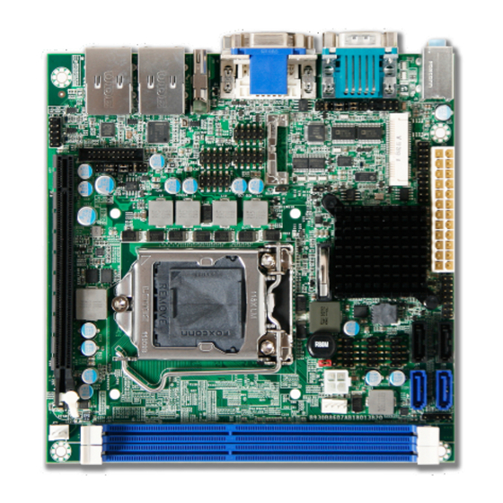
Page 7: Mechanical Drawing
System Overview 1.3.1 Mechanical Drawing WADE-8013/WADE-8014 User’s Manual... - Page 8 System Overview WADE-8013/WADE-8014 User’s Manual...
-
Page 9: System Architecture
System Overview System Architecture All of details operating relations are shown in WADE-8013 System Block Diagram. (WADE-8014 ‘s PCH is C216,support ECC memory) WADE-8013/WADE-8014 System Block Diagram WADE-8013/WADE-8014 User’s Manual... -
Page 10: Chapter 2 Hardware Configuration
Hardware Configuration This chapter gives the definitions and shows the positions of jumpers, headers and connectors. All of the configuration jumpers on WADE-8013/WADE-8014 are in the proper position. The default settings shipped from factory are marked with an asterisk (♣). - Page 11 JP5: PCIE Select Function Short[1 0] 2 x8 PCI Express Open[1 1] 1 x16 PCI Express 2x8 PCI Express for C216 Chipset JP6: CMOS Clear Function 1-2 Short Normal Operation 2-3 Short Clear CMOS Contents WADE-8013/WADE-8014 User’s Manual...
-
Page 12: Connector Allocation
Front Panel Pin Header J17/J18 SATA 2.0 Connector J19/J20/J21 USB 2.0 Pin Header +12V Power Connector SATA 3.0 Connector J23/J24 FAN (CPU FAN) Power Connector SMBUS Pin HEADER PCIE×16 Slot FAN (SYSTEN FAN) Power Connector J29/J30 DDR3 Slot HDMI Connector WADE-8013/WADE-8014 User’s Manual... - Page 13 J1B: VGA Connector PIN No. Signal Description PIN No. Signal Description Green Blue RGND GGND BGND KEY(+5V) SGND H Sync V Sync J2: COM1&COM2 J2A:COM1 Serial Port PIN No. Signal Description DCD#1 RXD#1 TXD#1 DTR#1 DSR#1 RTS#1 CTS#1 RI#1 WADE-8013/WADE-8014 User’s Manual...
- Page 14 PIN No. Signal Description DCD#5 DSR#5 RXD#5 RTS#5 TXD#5 CTS#5 DTR#5 RI#5 Ground J10: TPM Pin Header PIN No. Signal Description PIN No. Signal Description PCLK_TPM LFRAME# SIO2_PLTRST# LAD3 LAD2 VCC3 LAD1 LAD0 SMB_CLK_MAIN SMB_DATA_MAIN 3VSB SERIRQ LPCPD# WADE-8013/WADE-8014 User’s Manual...
- Page 15 PIN No. Signal Description PIN No. Signal Description GPIO0 GPIO4 GPIO1 GPIO5 GPIO2 GPIO6 GPIO3 GPIO7 Ground J14: GPIO Pin Header PIN No. Signal Description PIN No. Signal Description GPIO0 GPIO4 GPIO1 GPIO5 GPIO2 GPIO6 GPIO3 GPIO7 Ground WADE-8013/WADE-8014 User’s Manual...
- Page 16 J25: CPU Fan Connector PIN No. Signal Description Ground +12V Sense output FAN PWM_CONTROL J26: SMBUS Pin Header PIN No. Signal Description SMBus_CLK Ground SMBus_DAT J28: System Fan Connector PIN No. Signal Description Ground FAN PWM_CONTROL Sense output WADE-8013/WADE-8014 User’s Manual...
- Page 17 PIN No. Signal Description TMDA Data2+ Data2 Shield Ground TMDA Data2– TMDA Data1+ Data1 Shield Ground TMDA Data1– TMDA Data0+ Data0 Shield Ground TMDA Data0– TMDA Clock+ Clock Shield Ground TMDA Clock– Reserved DDC/CEC Ground +5V Power Hot Plug Detect WADE-8013/WADE-8014 User’s Manual...
-
Page 18: Chapter 3 System Installation
Alignment key Pin1 corner of the CPU Socket LGA-1155 CPU Notch Notch Yellow Triangle Pin1 of the CPU Please remember to locate the alignment keys on the CPU socket of the motherboard and the notches on the CPU. WADE-8013/WADE-8014 User’s Manual... - Page 19 Before install the CPU, please make sure to turn off the power first! 1. Open the load lever. 2. Lift the load lever up to fully open. 3. Remove the plastic cap on the CPU socket. Before you install the CPU, always cover it to protect the socket pin. WADE-8013/WADE-8014 User’s Manual...
- Page 20 Alignment key 5. Make sure the CPU has been seated well into the socket. If not, take out the CPU and reinstall. Alignment key 6. Engage the load lever while pressing down lightly onto the load plate. WADE-8013/WADE-8014 User’s Manual...
-
Page 21: Main Memory
8. Please make sure four hooks are in proper position before you install the cooler. Main Memory WADE-8013/WADE-8014 has two 240 pin DIMM sockets which supports Dual channel 1333/1600 DDR3-SDRAM as main memory, Non-ECC (Error Checking and Correcting), non-register functions. The maximum memory can be up to 16GB. -
Page 22: Installing The Single Board Computer
Step 1 : Check all jumpers setting on proper position Step 2 : Install and configure CPU and memory module on right position Step 3 : Place WADE-8013/WADE-8014 into the dedicated position in the system Step 4 : Attach cables to existing peripheral devices and secure it WARNING Please ensure that SBC is properly inserted and fixed by mechanism. -
Page 23: Audio Controller
ALC886 (High Definition Audio driver) form WADE-8013/WADE-8014 CD-title. The drivers support Windows 7. Clear CMOS Operation The following table indicates how to enable/disable Clear CMOS Function hardware circuit by putting jumpers at proper position. JP6: CMOS Clear Function 1-2 Short Normal Operation ... - Page 24 System Installation WADE-8013/WADE-8014 allows users to control WDT through dynamic software programming. The WDT starts counting when it is activated. It sends out a signal to system reset or to non-maskable interrupt (NMI), when time-out interval ends. To prevent the time-out interval from running out, a re-trigger signal will need to be sent before the counting reaches its end.
-
Page 25: Gpio
I/O function. GPIO Pin Assignment The WADE-8013 provides two groups of 8 input / output ports that can be individually configured to perform a simple basic I/O function. Users can configure each individual port to become an input or output port by programming register bit of I/O Selection. - Page 26 #define GPIO_MODE 0xCE // GPIO13 (J13) #else #define GPIO_MODE 0xCF // GPIO14 (J14) #endif static void set_ite_cfg (unsigned char Addr,unsigned char Value) write_io_byte (0X2E, Addr); write_io_byte (0X2E + 1, Value); static unsigned char get_ite_cfg (unsigned char Addr) WADE-8013/WADE-8014 User’s Manual...
- Page 27 (BASE + 6, &data); // BASE + 6 = GPIO13 #else // Set GP80~83 Low, 84~87 High write_io_byte (BASE + 7, 0x0F); // GPIO14 read_io_byte (BASE + 7, &data); // BASE + 6 = GPIO14 #endif WADE-8013/WADE-8014 User’s Manual 3-10...
-
Page 28: Chapter 4 Bios Setup Information
Chapter 4 BIOS Setup Information WADE-8013/WADE-8014 is equipped with the Phoenix BIOS stored in Flash ROM. These BIOS has a built-in Setup program that allows users to modify the basic system configuration easily. This type of information is stored in CMOS RAM so that it is... -
Page 29: Main
Use this menu for basic system configurations, such as time, date etc. System Date The date format is <Day>, <Month> <Date> <Year>. Use [+] or [-] to configure system Date. System Time The time format is <Hour> <Minute> <Second>. Use [+] or [-] to configure system Time. WADE-8013/WADE-8014 User’s Manual... -
Page 30: Advanced
BIOS Setup Information Advanced Use this menu to set up the items of special enhanced features. Boot Configuration Set Boot Configuration. WADE-8013/WADE-8014 User’s Manual... - Page 31 Diagnostic Summary Screen Display the Diagnostic summary screen during boot. Choices: Disabled, Enabled. Allow Hotkey in S4 Resume Enable hotkey detection when system resuming from Hibernate state. Choices: Disabled, Enabled. UEFI Boot Enable the UEFI boot. Choices: Disabled, Enabled. WADE-8013/WADE-8014 User’s Manual...
- Page 32 BIOS Setup Information PCI/PCIE Configuration Configure PCI/PCI Express slot. SERR# Generation Choices: Enabled, Disabled. Processor PCI Express Configuration WADE-8013/WADE-8014 User’s Manual...
- Page 33 Configure PEG3 B0:D6:F0 Speed. Choices: Auto, Gen1, Gen2, Gen3. PCH PCI Express Configuration DMI Link ASPM Control The control of active state Power Management on both NB side of the DMI Link. Choices: Disabled, L0s, L0sL1, Auto. WADE-8013/WADE-8014 User’s Manual...
- Page 34 Choices: Auto, Gen1, Gen2. ASPM Control PCIe Active State Power Management settings. Choices: Disabled, L0S, L1, L0S And L1, Auto. Hot PLUG PCI Express Hot Plug Enabled/Disabled. Choices: Disabled, Enabled. PCI Express Unsupported Request Reporting Enable/Disable. Choices: Disabled, Enabled. WADE-8013/WADE-8014 User’s Manual...
- Page 35 Choices: Disabled, Enabled. SECE Root PCI Express Device System Error on Correctable Error Enable/Disable. Choices: Disabled, Enabled. PME Interrupt Root PCI Express PME Interrupt Enable/Disable. Choices: Disabled, Enabled. PME SCI PCI Express PME SCI Enable/Disable. Choices: Disabled, Enabled. WADE-8013/WADE-8014 User’s Manual...
- Page 36 Select AC Power state when power is re-applied after a power failure. Choices: Power Off, Power On, Last State. SLP_S4 Assertion Stretch Enable Choices: Enabled, Disabled. SLP_S4 Assertion Stretch Width Choices: 1-2 Seconds, 2-3 Seconds, 3-4 Seconds, 4-5 Seconds. WADE-8013/WADE-8014 User’s Manual...
- Page 37 23, 24, 25, 26, 27, 28, 29, 30, 31. Wake up hour Choices: 0-23 Wake up minute Choices: 0-59 Wake up second Choices: 0-59 Wake up by Ring Choices: Enabled, Disabled. CPU configuration Configure the specific active core(s) and advanced processor management technologies. WADE-8013/WADE-8014 User’s Manual 4-10...
- Page 38 Choices: Disabled, Enabled. VT-x When enabled, a VWM can utilize the additional hardware capabilities provided by Vanderpool Technology. Choices: Disabled, Enabled. Local x2APIC Choices: Disabled, Enabled. C-States Enable processor idle power saving states (C-States). Choices: Disabled, Enabled. WADE-8013/WADE-8014 User’s Manual 4-11...
- Page 39 Configure onboard LAN device. Intel 82579LM GbE LAN Enabled/Disabled Intel 82579LM GbE LAN. Choices: Disabled, Enabled. Wake on LAN Enabled/Disabled Wake on LAN Function. Choices: Disabled, Enabled. LAN Boot ROM Control LAN Boot ROM (PXE) function. Choices: Disabled, Enabled. WADE-8013/WADE-8014 User’s Manual 4-12...
- Page 40 BIOS Setup Information Chipset Configuration Configure Chipset provide feature. VT-d Check to enable VT-d function on MCH. Choices: Disabled, Enabled. Audio Controller Control Detection of the Azalia device. Choices: Disabled, Enabled. WADE-8013/WADE-8014 User’s Manual 4-13...
- Page 41 To Enable the PEG Slot. Choices: Disabled, Enabled. PEG ASPM Control ASPM Support for the PEG Device. This has mp effect if PEF is not the current active device. Choices: Disabled, Auto, ASPM L0s, ASPM L1, ASPM L0sL1. WADE-8013/WADE-8014 User’s Manual 4-14...
-
Page 42: Memory Configuration
BIOS Setup Information Memory Configuration Memory Configuration Parameters. Memory Frequency Maximum Memory Frequency Selections in Mhz. Choices: Auto, 1067, 1333, 1600, 1867, 2133. WADE-8013/WADE-8014 User’s Manual 4-15... - Page 43 Select which of IGFX/PEG/PCI Graphics device should be Primary Display Or select SG for Switchable Gfx. Choices: Auto, IGFX, PEG, PCI. Internal Graphics Keep IGD Enabled based on the setup options Choices: Auto, Disabled, Enabled. Aperture Size Select the Aperture Size. Choices: 128MB, 256MB, 512MB. WADE-8013/WADE-8014 User’s Manual 4-16...
- Page 44 Choices: VBIOS Default, VGA, DVI, HDMI. Secondary Boot Display Choices: Disabled, VGA, DVI, HDMI. SATA Configuration Configure SATA controller and view detected HDD information. SATA Controller (s) Determines how SATA controller (s) operate. Choices: Disabled, Enabled. WADE-8013/WADE-8014 User’s Manual 4-17...
- Page 45 Designates this port as Hot Pluggable. Choices: Enabled, Disabled. External Port External SATA Support. Choices: Enabled, Disabled. SATA Device Type Identify the SATA port is connected to Solid State Drive or Hard Disk Drive. Choices: Hard Disk Driver, Solid State Driver. WADE-8013/WADE-8014 User’s Manual 4-18...
- Page 46 Configure USB controller and other advanced setting. Legacy USB Support Enables Legacy USB support. AUTO option disables legacy support if no USB devices are connected. DISABLE option will keep USB devices available only for EFI applications. Choices: Enabled, Disabled. WADE-8013/WADE-8014 User’s Manual 4-19...
- Page 47 BIOS Setup Information PCH USB Configuration PCH USB Configuration settings. USB Ports Per-Port Disable Control each of the USB ports disabling. Choices: Enabled, Disabled. WADE-8013/WADE-8014 User’s Manual 4-20...
- Page 48 BIOS Setup Information ME Configuration Configure Management Engine Technology Parameters. Intel (R) ME Enable/Disable Intel (R) Management Engine. Choices: Enabled, Disabled. WADE-8013/WADE-8014 User’s Manual 4-21...
- Page 49 Choices: Disabled, 3E8/IRQ5, 2E8/IRQB, 3E0/IRQ5, 2E0/IRQB. Serial Port 5 Choices: Disabled, 3E8/IRQ5, 2E8/IRQB, 3E0/IRQ5, 2E0/IRQB. Serial Port 6 Choices: Disabled, 3E8/IRQ5, 2E8/IRQB, 3E0/IRQ5, 2E0/IRQB. Watch Dog Timer Select Choices: Disabled, 15 secs, 30 secs, 1 min, 2 mins, 3 mins. WADE-8013/WADE-8014 User’s Manual 4-22...
-
Page 50: Hardware Monitor
BIOS Setup Information Hardware Monitor Provide on board sensor reading information. Smart Fan Control Feature WADE-8013/WADE-8014 User’s Manual 4-23... - Page 51 Choices: 25℃, 30℃, 35℃, 40℃, 45℃, 50℃, 55℃, 60℃, 65℃, 70℃, 75℃, 80℃, 85℃. Fan Full Speed Temp Choices: 50℃, 55℃, 60℃, 65℃, 70℃, 75℃, 80℃, 85℃. Serial Port Console Configuration Configure console redirection on serial port. Console Redirection Control Console Redirection enable/disable. Choices: Enabled, Disabled WADE-8013/WADE-8014 User’s Manual 4-24...
- Page 52 Long or noisy lines may require lower speeds. Choices: 9600, 19200, 57600, 115200. Flow Control Set flow control method for UCR. None – No flow control. RTS/CTS – Hardware flow control. XON/XOFF – Software flow control. Choices: None, Hardware RTS/CTS, Software Xon/Xoff. WADE-8013/WADE-8014 User’s Manual 4-25...
-
Page 53: Security
Press Enter to type Supervisor Hint String. Set User Password Set or clear the User account’ password. Supervisor Hint String Press Enter to type User Hint String. Min. password length Set the minimum number of characters for password (1-20). WADE-8013/WADE-8014 User’s Manual 4-26... -
Page 54: Boot
Boot Priority Order Keys used to view or configure devices: ↑ and ↓ arrows Select a device. ‘+’ and ‘-‘move the device up or down. ‘Shift + 1’ enabled or disables a device. ‘Del’ deletes an unprotected device. WADE-8013/WADE-8014 User’s Manual 4-27... -
Page 55: Exit
Load settings for optimized boot time and system performance. Discard Changes Load the original value of this boot time. Not the default Setup value. Save Changes Save all changes of all menus, but do not reset system. WADE-8013/WADE-8014 User’s Manual 4-28... -
Page 56: Chapter 5 Troubleshooting
Chapter 5 Troubleshooting This chapter provides a few useful tips to quickly get WADE-8013/WADE-8014 running with success. As basic hardware installation has been addressed in Chapter 2, this chapter will primarily focus on system integration issues, in terms of BIOS setting, and OS diagnostics. - Page 57 Troubleshooting Table. 5-1 SATA Mode setting guide System BIOS Main Menu Configuration SATA Configuration …….………… [Press enter] SATA Mode…… [IDE/AHCI/RAID] The J23 and J24 (Blue connector) SATA connectors can support SATA 3.0 hard disk. WADE-8013/WADE-8014 User’s Manual...
-
Page 58: Bios Setting
BIOS setting that Portwell has highly endorsed. As a matter of fact, users can load the default BIOS setting any time when system appears to be unstable in boot up sequence. -
Page 59: Q&A
Question: How to update the BIOS file of the WADE-8013/WADE-8014? Answer: 1. Please visit web site of the Portwell download center as below hyperlink and register an account. (The E-Mail box should be an existing Company email address that you check regularly.) - Page 60 5. Execute the zip file to root of the bootable USB pen drive which can boot to DOS mode. 6. Insert your bootable USB pen drive in WADE-8013/WADE-8014 board and power-on. 7. Boot to DOS mode then input the “Update” command to start to update BIOS process.
- Page 61 Usable IRQ 【Unassigned】 IRQ 10 Usable IRQ 【Unassigned】 IRQ 11 Usable IRQ 【Unassigned】 IRQ 12 System ROM IBM Mouse Event IRQ 13 System ROM Coprocessor Error IRQ 14 System ROM Hard Disk Event IRQ 15 Usable IRQ 【Unassigned】 WADE-8013/WADE-8014 User’s Manual...
- Page 62 System ROM Diskette Event IRQ 7 Usable IRQ 【Unassigned】 IRQ 8 System ROM Real-Time Clock IRQ 9 Usable IRQ 【Unassigned】 IRQ 10 Usable IRQ 【Unassigned】 IRQ 11 Video ROM Usable IRQ IRQ 12 System ROM IBM Mouse Event WADE-8013/WADE-8014 User’s Manual...
- Page 63 Troubleshooting IRQ 13 System ROM Coprocessor Error IRQ 14 System ROM Hard Disk Event IRQ 15 Usable IRQ 【Unassigned】 WADE-8013/WADE-8014 User’s Manual...
Need help?
Do you have a question about the WADE-8013 and is the answer not in the manual?
Questions and answers