Table of Contents
Advertisement
Advertisement
Table of Contents

Related Manuals for VIPColor VP700


Summary of Contents for VIPColor VP700
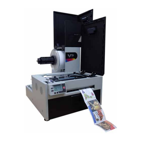
- Page 1 VIPColor VP700 Printer U s e r G u i d e...
- Page 2 Copyright © 2013 VIPColor Technologies. All rights reserved. No part of this document may be photocopied, reproduced, or translated to another language without the prior written permission of VIPColor Technologies. Trademarks Firefox is a trademark of the Mozilla Foundation. Intel and Intel Core are trademarks of Intel Corporation in the U.S. and/or other countries. Java and Oracle are registered trademarks of Oracle and/or its affiliates. Microsoft, Windows, Windows Vista, and Windows Server are registered trademarks of Microsoft Corporation in the U.S.A. and/or other countries. Edition VSEA1‐80002 VP700 Printer User Guide Edition 3. December 2013. FCC This device complies with Part 15 of the FCC rules. Operation is subject to the following two conditions: (1) this device may not cause harmful interference, and (2) this device must accept any interference received, including interference that may cause undesired operation.
-
Page 3: Safety Precautions
Safety Precautions Electrical Shock Hazard Do not disassemble any part of your printer. There are no user‐repairable parts inside the printer. Disassembly of any part of the printer will void all warranties. Fire Hazard Keep the printer well away from all heat sources and flammable substances. Switch your printer off immediately and unplug the power cord from the wall socket if you notice any of the following: • Smoke rising from the printer. • An acrid smell coming from the printer. • Sparks being emitted from printer. Contact your supplier as soon as possible. WARNING: Hazardous Moving Parts Keep fingers and other body parts away from the printer. Installation • Install the printer on a flat, level surface. The printer must remain level at all times. Tilting the printer may cause undue leakage of ink and affect performance and print quality. • Avoid wide temperature variations. Install the printer in a protected location away from direct sunlight, open windows or any other places subject to temperature extremes. Power Supply Input Rating 100–240 VAC, 50/60 Hz, 3.6 A Operating Temperature 15°C to 35°C • Always use the Power button on the control panel to turn the printer off. Removing power to the printer in any other manner may damage the printer. • Use only the supplied power cord. Use of any other power supplies or cords may damage the printer and void your warranty. - Page 4 Printer Usage • Ensure adequate ventilation to the printer. Blocking ventilation openings around the printer may cause it to overheat and become damaged. • Keep liquids and heavy objects away from the printer. Heavy objects may warp the outer shell, damaging the printer. Liquids may discolor or damage the skin and, if they penetrate it, may damage the printer beyond repair. • Use only authorized consumables. Use of any printhead other than authorized Memjet technology printheads will damage the printer and void your warranty. Use of unauthorized inks or ink cartridges may damage the printer and will void your warranty. • Clear media jams promptly. To avoid further problems, promptly attend to all media jams, as well as any other cause of printer failure. • If you are moving the printer, allow sufficient time after installation for the temperature and humidity of the internals of the printer to arrive at equilibrium with the surroundings.
-
Page 5: Table Of Contents
Contents Safety Precautions ............3 Setting Up the Printer ........7 Set Up the Printer............8 Troubleshoot Printer Setup .......... 12 Warranty Registration ........... 13 Change Security Passwords (Administrator) ...... 13 Additional Networking Information ........ 14 If the Printer Has a Static IP Address ....... . . 14 If the Connection to the Printer Has Changed ...... 14 Using the Printer.........15 Parts of the Printer ............ 16 Using the Control Panel .......... 17 Selecting the Security Level ......... . 19 Choosing Label Media........... . 20 Printing Labels ............ 23 Change Default Settings in Printer Driver ...... 23 Select the Media Type .......... 25 Adjust Alignment for Printing ........ 26 Printing Borderless (Full‐Bleed) Labels ........ 27... - Page 6 Troubleshooting .........59 If Error Messages Appear .......... 60 Poor Print Quality or Incorrect Printout ........ 62 Other Printing Problems .......... 65 Clearing a Media Jam........... . . 66 Clearing Clogged Ink Nozzles.......... 66 Adjusting Sensor Sensitivity .......... 68 Appendix ..........69 System Requirements........... . 70 Config Options on the Control Panel ........ 72 Printer Interface (GPIO) Specifications ........ 75 Regulatory Information .......... 78 Worldwide VIPColor Technologies Contacts ...... 80...
-
Page 7: Setting Up The Printer
Chapter 1 Setting Up the Printer Set Up the Printer 8 Troubleshoot Printer Setup 12 Warranty Registration 13 Change Security Passwords (Administrator) 13 Additional Networking Information 14 Set up the printer on a flat, level surface away from direct sunlight (see Safety Precautions on page 3). Ensure that there is: • A power outlet nearby. • Sufficient space to work with the printer. The media cover and top cover open upwards, and media loading is from the left side of the printer. Setting Up the Printer... -
Page 8: Set Up The Printer
Set Up the Printer Setting Up the Printer... - Page 9 Setting Up the Printer...
- Page 10 Loading Media Setting Up the Printer...
- Page 11 Setting Up the Printer...
-
Page 12: Troubleshoot Printer Setup
Troubleshoot Printer Setup If Mech Error 2 or Mech Error 3 appears on the control panel during installation, check the following: Possible Cause Solution Service station is jammed. Ensure that the cardboard is removed from inside the printer. Service station was tilted 1. Turn off the printer: Press the Power button on the control panel, then during shipment. press (Select) to confirm. When the LCD display turns off, turn off the Power switch at the back of the printer. 2. Open the clamshell to its highest position. 3. Rotate the positioning gear forward to eject the service station. 4. Push the service station back in, making sure it goes in straight. Check the alignment: the cap on the service station must be parallel with the edge of the platen. 5. Continue pushing the service station while you manually rotate the positioning gear backwards to move the service station all the way into the print engine. 6. Close the clamshell and turn on the printer. backward to install positioning gear forward to eject platen Setting Up the Printer... -
Page 13: Warranty Registration
Warranty Registration 1. On the Windows Start menu, select All Programs > VIPColor > VIPColor VP700 Label Printer > Warranty Registration. You will be redirected to the warranty website. 2. Follow the instructions to register. Change Security Passwords (Administrator) Once the printer has been set up, an administrator should change the security passwords using the Embedded Web Server (EWS). 1. On the Windows Start menu, select All Programs > VIPColor > VIPColor VP700 Label Printer > Toolbox. 2. Click VIPColor VP700 Label Printer to launch the default web browser and open the EWS for your printer. 3. Click Login and log in with the default password 123. 4. Click Security Setup to change the password for the EWS as well as the passwords for the control panel (default password 123). See Managing Printer Security (Administrator) on page 31 for more information about security on this printer and Embedded Web Server (EWS) on page 33 on the EWS. Set Date and Time From the EWS, also set the date and time on the printer by synchronizing with the host computer. This option can be found in Advanced Settings. Setting Up the Printer... -
Page 14: Additional Networking Information
Additional Networking Information If the Printer Has a Static IP Address DHCP is enabled by default. If DHCP is not available and the printer is assigned a static IP address, set the static IP address from the control panel before installing the printer driver. 1. Press (Config) on the control panel to access the configuration menus. Level 2 security is required to change network settings (see Selecting the Security Level on page 19). 3. Scroll to the NETWORK menu to make the changes: DHCP Setting Set to Manual. IP Settings Enter the static IP settings for the printer. • Static IP • Subnet Mask • Gateway • WINS Server a. Press and to set each digit (0 to 9). b. Press to move to the next digit. 4. Connect the printer to the network. 5. Insert the printer setup disc into the computer’s disc drive to continue with the printer driver installation for a network printer. If the Connection to the Printer Has Changed If the printer has been set up using a USB connection and is later connected via the network (or vice versa), reinstall the printer driver. 1. Network – Connect the printer to the network. USB – Do not connect the printer at this point. You will be prompted to do so during the driver setup. -
Page 15: Using The Printer
Chapter 2 Using the Printer Parts of the Printer 16 Choosing Label Media 20 Printing Labels 23 Printing Borderless (Full‐Bleed) Labels 27 Export/Import Custom media size settings 28 Turning Off the Printer 29 Managing Printer Security (Administrator) 31 Software Tools 33 Using the Printer... -
Page 16: Parts Of The Printer
Parts of the Printer Media Cover Top Cover Output Slot Control Panel Front Cover GPIO Port USB Port Ethernet Port Power Socket Power Switch Using the Printer... -
Page 17: Using The Control Panel
Using the Control Panel The printer is ready to print when the control panel displays Printer Online. The Data and Status LEDs together with messages indicate the printer status and any potential problems (Table 1). The control panel also shows the estimated levels of the ink cartridges. In the example below, the yellow ink cartridge level is between 25 to 50%. The icons above the printer buttons indicate their functions, which change depending on the current operation (see Table 2). Printer Online Power LED Data LED Power Button Status LED Ink Status Printer Buttons Table 1 Printer LEDs Description Data LED Blinking Printer is receiving data from the computer. There are print jobs in the printer memory. Status LED Blinking • Printhead is being serviced, or • Attention needed; a message will be displayed. (See If Error Messages Appear on page 60.) • An error has occurred; a message will be displayed. (See If Error Messages Appear on page 60.) The icons above the printer buttons indicate their functions (Table 2). • When the printer is online, press (Config) to access the configuration menus. The options are described in Config Options on the Control Panel on page 72. • Press and to scroll through the menus. - Page 18 • Press (Return) to return to the previous menu. Printer Online CONFIGURATION 1. Setup Table 2 Printer Buttons Function Description Config Access the Configuration menus. Up, Down Move through the menu options. Select Select a menu option or confirm a setting. Return Return to previous menu. Unload Media Unload the labels. Pause, Resume Pause or resume printing. If printing Roll to Roll, the printer pauses for 10 seconds, then prints the next page and pauses again. It will continue to print and pause. Cancel Cancel printing. Using the Printer...
-
Page 19: Selecting The Security Level
Selecting the Security Level By default, the printer powers up in security Level 0 (operator), which does not allow changes to some printer parameters. To make changes, select security Level 1 (supervisor) and enter the password provided by your administrator. Security Level 2 gives administrator access to all functions. Level 1 or Level 2. 1. On the control panel, select (Config) SETUP SECURITY 2. Enter the 3‐digit password. Printer Online (Config) CONFIGURATION 1. SETUP (Select) SETUP 2. SECURITY (Select) SECURITY 2. Level 1 (Select) ENTER PASSWORD Press , to set. Press to move to next digit. -
Page 20: Choosing Label Media
Choosing Label Media Ensure that the label media meets the requirements for the printer (see Table 3 and the following illustrations). Always test the media first to see if it meets your expectations. To check the compatibility of label media, print the barcodes test page. Table 3 Media specifications Media Type and Dimensions Media type Gloss, semi‐gloss, and matte. Label width 2.0” to 8.5” (50.8 mm to 215.9 mm) Label length Continuous/Roll to Roll: Maximum 40” (1.016 m) Roll to Cut/Print and Present: Maximum 8" (203.2mm) Label thickness Maximum 0.01” (0.3 mm) (including liner, if any) Minimum 0.005” (0.13 mm) Core size 3” (76.2 mm) Roll diameter Maximum 8” (203.2 mm) Media Handling Print mode • Roll to Cut • Print and Present (non‐peel) • Roll to Roll Detection • Gap • Continuous • Black mark Figure 1 Media Roll Coating on the outside Minimum Maximum 3.0” (76.0 mm) cardboard core 3.0” (76.0 mm) cardboard core Up to 8.0” (203.0 mm) ... - Page 21 Figure 2 Gap (Transmissive) Media Minimum Maximum 0.125”(3.0 mm) 0.3” (8.0 mm) 2.0” (50.8 mm) 0.4” (10mm) 2.0” (50.8 mm) 8.5” (216.0 mm) 2.0” (50.8 mm) 40.0” (1016.0 mm) Figure 3 Black Mark (Reflective) Media Reverse side of tag stock Minimum Maximum 2.0” (50.8 mm) 8.5” (216.0 mm) 2.0” (50.8 mm) 40.0” (1016.0 mm) 1.0” (25.4 mm) 8.5” (216.0 mm) 0.125” (3.0 mm) 0.3” (8.0 mm) Using the Printer...
- Page 22 Print Test Page Load 4” x 4” or larger labels (with inter‐label gap or continuous). PRINT TEST PAGE 1. On the control panel, select (Config) MAINTENANCE Barcodes. Sample Barcodes Test Page Printer Online (Config) CONFIGURATION 2. MAINTENANCE (Select) MAINTENANCE 1. PRINT TEST PAGE (Select) PRINT TEST PAGE 1. Barcodes (Select) 2. Verify the following on the test page: • Label is printed in black with no other color visible. • The text is legible. • The barcodes are readable. •...
-
Page 23: Printing Labels
Printing Labels The printer is ready to print when the control panel displays Printer Online. 1. Select the Print command from your application. 2. Select the printer and click the Setup, Properties or similar button. The print settings displayed are the defaults that were set in the printer driver. 3. Change the print settings if needed. NOTE: Ensure the media settings (e.g. label size) match the media loaded in the printer. 4. Print the document. Any changes to the settings only apply to the current print job. Once you exit the application, the changes may be lost. Make the changes in the printer driver if you wish to keep the settings as the default for all print jobs. Change Default Settings in Printer Driver To select the default print settings that will be used for all print jobs: 1. From the Windows Start menu, select Devices and Printers 2. Right‐click the printer, and select Printing preferences. The printing preferences contain three tabs as shown in Figure 4. 3. Make the changes and click OK to save. 1. For Windows 7. The steps will differ for other Windows versions. Using the Printer... - Page 24 Figure 4 Printing Preferences Print pages without any gap (continuous media only) Render entire document to disk before sending to the printer. Select this option if labels are skipped when printing large files. Select the Media Type that matches the media loaded in the printer. Adjust horizontal and vertical print position. Sheets per cut – Cut after printing the specified number of labels. Print and Present – Print, cut, and present label. Remove the label to continue printing. Roll to Roll – Select Roll to Roll if a rewinder is used. Choose whether to print the first label or print multiple jobs without cuts in‐between. Using the Printer...
-
Page 25: Select The Media Type
Select the Media Type Selecting the media type that matches the media you are printing on will usually give the best print results. Select this Media Type: When you are printing on: Plain Paper Plain (uncoated) paper and labels. Matte Coated Label Matte coated labels. Premium Matte Coated Matte coated labels. This option uses more ink for Label better color. Glossy Label Glossy labels. This option optimizes print quality and dry time. Premium Gloss Label Glossy labels. This option uses more ink for better color. Using the Printer... -
Page 26: Adjust Alignment For Printing
Adjust Alignment for Printing Always print a few test labels to check the alignment of the image. If the image is not centered, adjust the top of form and/or left edge offsets on the Media tab of the printer driver. A positive value for Top of Form adjusts the image towards the top of the label. A positive value for Left Edge adjusts the image towards the left of the label. – – Offset settings Using the Printer... -
Page 27: Printing Borderless (Full-Bleed) Labels
Printing Borderless (Full‐Bleed) Labels The usual approach to borderless printing is to prepare an image slightly larger than the label size, then center the larger image over the label so that it prints over the edges. The following procedure describes where to make the adjustments on the VP700 printer. Note the following: • This method requires fine‐tuning of the printing position, which will be difficult if the label gap is very small e.g. 0.1” (3 mm). • As the maximum label width is 8.5” (215.9 mm), it is also difficult to print borderless labels of this size. This method works best when the label width plus bleed allowance does not exceed 8.5” (215.9 mm). • Print at 6 IPS only. • You may need to fine‐tune the Top of Form/Bottom of Form/Left Edge offset on the control panel for each label size. For example, the offsets for a 6” x 4” label may be different from a 2” x 2.5” label. Hence, you need to record the offsets used for each label size. Adjustments for Borderless Printing 1. On the General tab of the printer driver (Figure 4), click Custom Sizes to set the page size slightly smaller than the label (about 0.01” or 0.2 mm in both direction). Select Print Speed of 6 IPS and enable Borderless. 2. On the Media tab, adjust the Left Edge to center the image on the label. 3. Print a few labels to check the print position. Fine‐tune using the printer control panel: OFFSET (Config) ADJUST Top of Form/Bottom of Form/Left Edge ... -
Page 28: Export/Import Custom Media Size Settings
Export/Import Custom media size settings Any custom media size settings will be lost if the printer driver is updated. Make a backup copy of these settings by saving them to a file. At any time when you update the printer driver, you may re‐import these settings from the backup file. Export Custom media size settings 1. On the Import/Export tab of the printer driver, select Media Sizes. 2. Click Export. 3. Enter a filename and click Save. Import Custom media size settings 1. On the Import/Export tab of the printer driver, select Media Sizes. 2. Click Import. 3. Select the file that you wish to import your settings and click Open. Select this option Using the Printer... -
Page 29: Turning Off The Printer
Turning Off the Printer Always use the Power button to turn off the printer. Removing power to the printer in any other manner may damage the printer. 1. Press the Power button on the control panel, then press (Select) to confirm. Printer Online SWITCH OFF 1. Confirm 2. Wait for the LCD display on the control panel to turn off, then turn off the Power switch at the back of the printer. During a normal shutdown, the printer will service the printhead and save data to the memory before turning off. Using the Printer... - Page 30 If the Printer Will Not Switch Off If the printer does not respond when you press the Power button, press and hold the power button for 5 seconds. The printer should switch off. However, it will not be able to perform the normal shutdown processes. Do not use this option unless it is absolutely necessary. Using the Printer...
-
Page 31: Managing Printer Security (Administrator)
Level 0 The printer powers up in level 0 by default, which allows users to (operator) access all the functions needed to print, but not to change printer parameters via the control panel. Level 1 The user can access certain printer parameters. A password is (supervisor) required to access this level. Level 2 All parameters are enabled. A password is required to access this (administrator) level. The administrator can change the passwords through the Embedded Web Server (EWS). It is recommended that the administrator change the passwords once the printer has been set up. The default password is 123 for the EWS and the printer control panel. Change Passwords 1. Log in to the EWS. a On the Windows Start menu, select All Programs > VIPColor > VIPColor VP700 Label Printer > Toolbox. b Click VIPColor VP700 Label Printer to launch the default web browser and open the EWS for your printer. c Click Login to log in with your admin password. 2. Select Security Setup, then select Printer Password. Using the Printer... - Page 32 3. Set the password and click Submit. • The EWS password can have 3 to 12 alphanumeric characters. Special characters are not allowed. • The control panel password must contain 3 digits. Change Security Level for Printer Settings The administrator can change the security level for the following protected printer settings, which are enabled at Level 1 by default. 1. Log in to the EWS. 2. Select Security Setup followed by Printer Security. 3. From the dropdown list, select the minimum security level allowed to access each setting. For example, if you set Language to Level 0 - Operator, then all security levels will have access to this setting. 4. Click Submit. Using the Printer...
-
Page 33: Software Tools
Software Tools • Embedded Web Server (EWS) • Support Tools Embedded Web Server (EWS) The Embedded Web Server (EWS) provides remote access to the printer. You can monitor the printer status and check usage metrics. The administrator can also log in to view additional information and change various settings. 1. On the Windows Start menu, select All Programs > VIPColor > VIPColor VP700 Label Printer > Toolbox. 2. Click VIPColor VP700 Label Printer to launch the default web browser and open the EWS for your printer. The EWS displays printer information and usage metrics on the Printer Status page. Click Login to log in for full access to all the EWS pages (described in Table 4). 1. Recommended: Internet Explorer 8/Firefox 15 or later, at 1280 x 700 or higher resolution. Using the Printer... - Page 34 Table 4 EWS pages EWS Page Description Printer Status Shows printer and printhead information, ink levels, usage metrics. Also shows the current printer settings. Ink usage metrics can be exported. Right‐click the EXPORT link and select Save Target As to save the data in a file. Security Setup (See Managing Printer Security (Administrator) on page 31.) Change Password Set the passwords for accessing the following: • Embedded Web Server (EWS). The EWS password can have 3 to 12 alphanumeric characters. Special characters are not allowed. • Level 1 (Supervisor) security on control panel. • Level 2 (Administrator) security on control panel. The control panel password must contain 3 digits. Printer Settings Set the minimum security level allowed to access the following protected settings: • Language • LCD Brightness/Contrast • Sensor Sensitivity Network Configuration Network settings for the printer. Diagnostics Print test pages. Load 4” x 4” or larger labels (with inter‐label gap or continuous). • Specify whether the media loaded in the printer is Continuous or with Inter‐Label Gap and click Submit....
-
Page 35: Support Tools
• Multiple Job Queue: Allowable timeout between jobs When the printer is set up to print multiple jobs (with no cut between job), this value specifies the max. allowable time for consecutive jobs before the printer cuts. This prevents printhead damages, as the result of prolonged uncapped time. Note: These EWS settings will only appear in printers that are specifically configured (at the factory) with the internal unwinder disabled. Other settings • Retract media when printer is idle for 10 or 30 minutes (default) When media remains in the printer for some time, it may become deformed and printing is affected. To avoid this problem, select this option to automatically retract the media. • Enable virtual printing Simulate printing to estimate ink usage. a) Select Enable virtual printing. b) Print in the usual way. The printer will not actually print, but will estimate ink usage for the print job. c) On the Printer Status page, select Ink Status to view the estimates. The control panel will display Simulation when the printer is in this mode. Support Tools On the Windows Start menu, select All Programs > VIPColor > VIPColor VP700 Label Printer > Support Tools. Using the Printer... - Page 36 The Support Tools consist of the following: • Get Tech Support: Opens the Technical Support web page. • Buy Consumables: Opens the consumables web page for you to purchase ink supplies online. • Update Firmware: Helps you to update the printer firmware. • Get Printer Info: Displays a log of printer activity and errors. This may be required when you contact Technical Support. • Contact Info: Allows you to save your contact information, which will be included in the Printer Info log. Using the Printer...
- Page 37 Using the Printer...
-
Page 38: Printer Maintenance
Chapter 3 Printer Maintenance Guidelines for Preventive Maintenance 38 Replacing an Ink Cartridge 39 Cleaning the Printhead 40 Replacing the Printhead 41 Opening/Closing the Clamshell 44 Cleaning Debris from the Cutting Zone 46 Cleaning the Sensors 47 Replacing the Output Module/Cutter Assembly 48 Replacing the Service Station 52 Replacing the Transfer Wiper Assembly 55 Replacing the Aerosol Fan Filter 57 Replacing the Waste Ink Absorber 58 Printer Maintenance... - Page 39 Guidelines for Preventive Maintenance Recommended maintenance depends on the print mode that is most frequently used. If you mostly print Roll to Roll (≥80%), refer to Table 5. Otherwise, see Table 6. Inspect means to check the condition and replace if necessary. Note that these are general guidelines for preventive maintenance. As operating conditions for your printer may differ, adjust your maintenance schedule accordingly. Table 5 Maintenance Schedule: For ≥80% Roll to Roll Operation Part Every 1M inches Every 2.5M inches Every 5M inches (25,400 m) (63,500 m) (122,500 m) Sensors Clean – – Cutter Assembly MM007‐64506 – Inspect Replace Output Module VMAG1‐60008A – Inspect Replace Service Station MM007‐65502 Inspect Replace – Transfer Wiper Assembly MM007‐65505 Inspect Replace –...
-
Page 40: Replacing An Ink Cartridge
Replacing an Ink Cartridge Do not open the front cover if the control panel shows Servicing Printhead. Wait for the servicing to be completed first. 1. Open the front cover of the printer. 2. Open the latch and remove the empty ink cartridge. 3. Insert the new cartridge and close the latch. 4. Close the front cover. NOTE: Dispose of the empty ink cartridge according to local regulations. Printer Maintenance... -
Page 41: Cleaning The Printhead
Cleaning the Printhead The printer provides three automated cleaning cycles for the printhead: Normal, Extended, and Extreme. Always start with the Normal cleaning cycle and proceed to the next level only if print quality does not improve. 1. On the control panel, select (Config) PRINTHEAD CLEAN Normal. Printer Online (Config) CONFIGURATION 3. PRINTHEAD (Select) PRINTHEAD 1. CLEAN (Select) CLEAN 1. Normal (Select) 2. After the cleaning is completed, try printing again. Printer Maintenance... -
Page 42: Replacing The Printhead
Replacing the Printhead Make sure all the ink cartridges are installed before replacing the printhead. 1. Open the printer top cover. 2. On the control panel, select (Config) PRINTHEAD Replace. Wait for the printhead latch to be released. 3. When the printhead latch is released, open the latch fully. Printer Maintenance... - Page 43 4. Hold the printhead by the handle and push it toward the printhead latch. Once the printhead is released, lift it out of the printer. NOTE: Dispose of the old printhead according to local regulations. 5. Remove the new printhead from its packaging. Do not touch the ink couplings, electrical contacts, or nozzles. ink couplings NOTE: Keep the orange cover. You will need it to cap the printhead if it is removed from the printer. nozzles electrical contacts No less than 45° Printer Maintenance...
- Page 44 6. Slide the printhead into the slot. Push it toward the front of the printer. It should snap into place. 7. Close the printhead latch. Check that ink is flowing through the tubes on both sides of the printhead. 8. Close the top cover. Printer Maintenance...
-
Page 45: Opening/Closing The Clamshell
Opening/Closing the Clamshell In the following procedures you may need to open the clamshell in order to access the areas inside the printer. Opening the Clamshell Do not open the top cover if the control panel shows Servicing Printhead. Wait for the servicing to be completed first. 1. Open the top cover. 2. Squeeze the latches on either side of the clamshell and open the clamshell to its highest position. squeeze clamshell latches Clamshell open Printer Maintenance... - Page 46 Closing the Clamshell Squeeze and hold the clamshell latches while you gently lower the clamshell back into place. Do not allow the clamshell to drop when closing it. Printer Maintenance...
-
Page 47: Cleaning Debris From The Cutting Zone
Cleaning Debris from the Cutting Zone Clear all debris from the cutting zone to avoid contaminating the print zone, especially fine dust particles. 1. Open the top cover. 2. Vacuum any debris from the cutting zone (shown in green). cutter path 3. Open the clamshell and also check below the cutting zone, at the bottom of the printer and in front of the ink cartridges. Printer Maintenance... -
Page 48: Cleaning The Sensors
Cleaning the Sensors Always keep the media path clean as accumulated dust can affect printing. 1. Open the clamshell to its highest position. 2. Vacuum any dust or debris from the sensors. Use the rollers to help you locate the sensors as shown in Figure 5. 3. Clean ink from the exit sensor if it looks dull: a Fold a lint‐free cloth to form a tip and lightly moisten with de‐ionized water. Insert it in the opening to clean the exit sensor. b Repeat with a clean part of the cloth if necessary. c Let the sensor dry before continuing. 4. Close the clamshell and top cover. Do not vacuum the printhead. Figure 5 Location of sensors second roller first roller Transmissive and reflective sensors behind the second roller Exit sensor behind the first set of rollers Printer Maintenance... -
Page 49: Replacing The Output Module/Cutter Assembly
Replacing the Output Module/Cutter Assembly Tools • Nitrile powder‐free gloves • Small flat‐heat screwdriver • T10 Torx driver • Scissors or cutter (for cable ties) • Cable ties Keep the cutting zone free from debris. Check cut labels to ensure that the cuts have clean edges and replace the cutter assembly when necessary. NOTE: Before you begin, remove the printhead and cap it with the orange protective cover. Removal 1. Press the Power button on the control panel to turn off the printer. Also turn off the Power switch at the back of the printer. 2. Open the clamshell to its highest position. 3. Locate the wire harness connector (labeled P107) for the output module (Figure 6). Use a small flat‐head screwdriver to release the connector and separate it. 4. Carefully cut the cable ties securing the cables to the left side of the clamshell. Be careful not to cut any of the cables. Printer Maintenance... - Page 50 Figure 6 Connectors and cables on left side of clamshell connector for output module connector for cutter assembly 5. Use a T10 Torx driver to remove the four screws securing the output module. Remove the outer screws (a) first. 6. Carefully remove the output module from the clamshell. There is a black cable looped across the bottom of the output module. Gently pull the cable away from the bottom corners of the output module and ease the output module out. The cutter assembly is now visible (Figure 7). Printer Maintenance...
- Page 51 Replace Cutter Assembly If replacing the cutter assembly, continue with the following steps. 1. Use a small flat‐head screwdriver to release the wire harness connector for the cutter assembly (labeled CUTTER MODULE) and separate it (Figure 6). 2. Remove the two screws (a) securing the cutter assembly and remove the assembly (Figure 7). Figure 7 Cutter assembly on clamshell notch cable 3. Line up the mounting holes and guides on the new cutter assembly and the front of the clamshell. Insert and tighten the screws to secure the assembly. 4. Make sure the cutter is at the side of the cutter assembly. cutter notch guide for cable guide 5. Reattach the wire harness connector (labeled CUTTER MODULE) for the cutter assembly at the side of the clamshell (Figure 6). Be sure to reattach the correct connector for the cutter assembly. 6. Gently pull the black cable out of the notches at the bottom corners of the cutter assembly so that the output module can be installed. Printer Maintenance...
- Page 52 Installation 1. Seat the output module on the cutter assembly, aligning the mounting holes for the screws. 2. Loop the black cable over the bottom of the output module, pushing it back into the notches at the corners of the cutter assembly. 3. Replace the four screws securing the output module. Replace the two screws in the center (b) before replacing the outer ones. 4. Reattach the wire harness connector (labeled P107) for the output module at the side of the clamshell (Figure 6). Be sure to reattach the correct connector for the output module. 5. Tidy the cables at the side of the clamshell and secure with cable ties (Figure 6). 6. Carefully close the clamshell while checking that none of the cables will get caught or pinched. 7. Close the top cover. Printer Maintenance...
-
Page 53: Replacing The Service Station
Replacing the Service Station NOTE: Before you begin, remove the printhead and cap it with the orange protective cover. Tools • Nitrile powder‐free gloves • T20 Torx driver • Disposable towels Removal 1. Open the clamshell to its highest position. SERVICE STATION 2. On the control panel, select (Config) Eject. Wait for the printer to eject the service station. 3. Press the Power button on the control panel to turn off the printer. Also turn off the Power switch at the back of the printer. 4. Remove the front panel: a Use a T20 Torx driver to remove the four screws (labeled 1 to 4) securing the front panel. b Release the front panel and disconnect the two cables behind the control panel. cables behind control panel Printer Maintenance... - Page 54 5. Pull the service station forward until you can disconnect the flex cable to the wiper motor. Loosen the clip on the connector (Figure 8) to release the flex cable. flex cable Ensure that the flex cable does not come into contact with any metallic surface. If it is touching metal and the printer is accidently turned on, it will short the controller circuit and damage the printer. Take care when handling the service station. Ink may spill when you tilt the service station. NOTE: Dispose of the old service station according to local regulations. Installation 6. Insert the flex cable into the connector on the new service station and push in the clip to secure it. Figure 8 Flex cable to connector on service station flex cable clip Printer Maintenance...
- Page 55 7. Carefully align the service station with the guide rails and slide it into the print engine. Push it in by applying even pressure near the edges, to ensure that the it goes in straight. guide rail Check the alignment: the cap on the service station must be parallel with the edge of the platen as shown below. If the service station is skewed sideways, pull it out and reinsert. platen 8. Continue pushing the service station while you manually rotate the positioning gear backwards to move the service station all the way into the print engine. 9. Reinstall the front panel: Reconnect the two cables to the front panel and replace the screws. 10. Close the clamshell and the covers. 11. Turn the printer on. Printer Maintenance...
-
Page 56: Replacing The Transfer Wiper Assembly
Replacing the Transfer Wiper Assembly Removal 1. Follow the instructions to remove the service station. 2. Disconnect the wiper motor cable from the PCB. 3. Release the PCB from the mounting clip. mounting clip wiper motor cable 4. Route the cable through the housing as you remove the transfer wiper assembly. wiper roller NOTE: Dispose of the old transfer wiper assembly according to local regulations. Printer Maintenance... - Page 57 Installation 5. Route the wiper motor cable through the housing as you insert the new transfer wiper assembly into the service station. 6. Push the cable between the clips. Align the PCB with the mounting clip and push gently into place. 7. Connect the wiper motor cable to the PCB. 8. Install the service station in the printer. Printer Maintenance...
-
Page 58: Replacing The Aerosol Fan Filter
Replacing the Aerosol Fan Filter You can replace the aerosol fan guard or just replace the fan filter. Tools • Nitrile powder‐free gloves • Flat‐head screwdriver To replace the fan filter: 1. Open the clamshell to its highest position. 2. Insert the tip of a flat‐head screwdriver into the slot at the corner of the aerosol fan guard, and pry the cover off. 3. Do the same with the new aerosol fan guard, and remove the filter (Figure 9). 4. Remove the old filter from the printer and insert the new filter. 5. Snap the cover back into place on the aerosol fan guard. 6. Close the clamshell and top cover. Figure 9 Aerosol fan guard slot aerosol fan guard cover filter To replace the entire aerosol fan guard, carefully remove the four screws at the corners of the fan guard. Align the new fan guard with the mounting holes and replace the screws. Printer Maintenance... -
Page 59: Replacing The Waste Ink Absorber
Replacing the Waste Ink Absorber Tools • Nitrile powder‐free gloves 1. Open the front cover of the printer. 2. Squeeze the latches on both sides of the waste ink tray and pull it out. 3. Remove the waste ink absorber and replace it with a new one. 4. Slide the waste ink tray into the printer. Push it in till it clicks into place. 5. Close the front cover. NOTE: Take care when replacing the waste ink absorber to avoid staining hands and clothing. Dispose of the used waste ink absorber according to local regulations. Printer Maintenance... -
Page 60: Troubleshooting
Chapter 4 Troubleshooting If Error Messages Appear 60 Poor Print Quality or Incorrect Printout 62 Other Printing Problems 65 Clearing a Media Jam 66 Clearing Clogged Ink Nozzles 66 Adjusting Sensor Sensitivity 68 Troubleshooting... -
Page 61: If Error Messages Appear
If Error Messages Appear If error messages are displayed on the printer control panel, check the following table for the solution. Error Message Possible Cause Solution Clamshell Open The clamshell is open. Close the clamshell. End of Roll End of roll is detected. Load a new roll of labels. Front Cover Open The front cover is open. Close the front cover. Jammed Cutter Debris in the cutting zone. 1. Turn off the printer and unplug the power cable. 2. Clean any debris from the cutting zone. See Cleaning Debris from the Cutting Zone on page 46 for details. Jammed Media The labels are jammed or cannot Clear the jam and reload the media. feed into the printer. See Clearing a Media Jam on page 66. Media used exceeds the maximum Clear the jam and replace the media. See thickness of 0.01” (0.3 mm). Choosing Label Media on page 20. Low Ink An ink cartridge is low. Replace the ink cartridge. Check the ink status icons for the color that is running out. Mech Error [code] Printer mechanical fault. Note the error code and contact Technical Support. - Page 62 Error Message Possible Cause Solution Out of Ink An ink cartridge is out of ink. Replace the ink cartridge. Check the ink status icons for the color that is empty. Top Cover Open The printer top cover is open. Close the top cover. Troubleshooting...
-
Page 63: Poor Print Quality Or Incorrect Printout
Poor Print Quality or Incorrect Printout Problem Possible Cause Solution Long stripes of missing Ink nozzles are clogged. See Clearing Clogged Ink Nozzles on page 66. print or vertical light streaks on several labels Printed barcode cannot The media is not suitable for Replace the media. See Choosing Label Media be scanned use in this printer. on page 20. The barcode is too small. Adjust the size of the barcode. Ink nozzles are clogged and the See Clearing Clogged Ink Nozzles on page 66. barcode did not print properly. Ink is smudged on the The media is not suitable for Replace the media. See Choosing Label Media labels use in this printer. on page 20. Accumulated ink in the print 1. Open the clamshell and inspect the print zone. zone (Figure 10). 2. Lightly moisten a a lint‐free cloth with de‐ionized water and gently clean off any ink from the print zone and printhead. 3. Close the clamshell. The media is curled and Replace the media. See Choosing Label touching the printhead. - Page 64 Problem Possible Cause Solution Mixed or muddy colors The printhead is dirty. 1. Run Extended cleaning cycle from the control panel ( (Config) MAINTENANCE CLEAN Extended). If print quality shows some improvement, repeat Extended cleaning until the print quality is satisfactory. If print quality does not improve, open the clamshell and check for patches of wet ink on the printhead. 3. Use a lint‐free cloth to absorb the ink. Avoid touching the neighboring nozzles. 4. Check the print quality. Run Extended cleaning cycle if necessary. Color ink cartridges are dirty. 1. Remove the yellow (Y) ink cartridge from the printer. 2. Check the color of the ink through the ink level prism. ink level prism If the ink color is very dark (black) instead of yellow or iodine, replace all three color ink cartridges. Position of printed Top of Form position needs ...
- Page 65 Problem Possible Cause Solution Mis‐registration or Media settings do not match Make sure the settings are correct for the media labels are skipped the media loaded in the printer. (e.g. media size and orientation). The media does not meet the See Choosing Label Media on page 20 for the specifications. media specifications. The printer is unable to 1. Clean the sensors. See Cleaning the Sensors correctly detect the inter‐label on page 47. gap or black mark. 2. If the problem persists, adjust the sensitivity of the sensors. See Adjusting Sensor Sensitivity on page 68. Labels are skipped The printer is unable to Adjust the media size in the printer driver: when printing Roll to correctly detect the inter‐label reduce the height by 0.1” (3 mm). Roll on media with black mark. black mark Troubleshooting...
-
Page 66: Other Printing Problems
Other Printing Problems Problem Possible Cause Solution Printer feeds media without Media settings do not match Make sure the Media Layout setting (gap, printing and then displays the media loaded in the black mark, or continuous) in the printer Wrong media on the LCD. printer. driver matches the media used. The media does not meet the See Choosing Label Media on page 20 for the specifications. media specifications. The printer is unable to Clean the sensors. See Cleaning the correctly detect the inter‐label Sensors on page 47. gap or black mark. 2. If the problem persists, adjust the sensitivity of the sensors. See Adjusting Sensor Sensitivity on page 68. Labels are not cut. The exit sensor needs cleaning. Clean the exit sensor. See Cleaning the Sensors on page 47. Changes made using the The changes were not saved 1. Try changing the parameter again. control panel did not take properly due to user or 2. -
Page 67: Clearing A Media Jam
Clearing a Media Jam 1. Open the media cover. 2. Cut off the jammed media from the media roll. 3. Open the clamshell to its highest position. 4. Remove the jammed media from inside the printer. 5. Close the clamshell and top cover. 6. Reload the media. Clearing Clogged Ink Nozzles Long stripes of missing print or vertical light streaks on several labels may be an indication of clogged ink nozzles. Follow the procedure below to clear the ink nozzles. After each step, print and check the print quality. Proceed to the next step only if the problem persists. 1. Open the clamshell and inspect the print zone (the area below the clamshell as shown in Figure 10). Vacuum any dust or debris from the area. NOTE: Do NOT clean the printhead at this point. Figure 10 Print zone clamshell printhead print zone Troubleshooting... - Page 68 2. From the control panel, run Normal printhead cleaning. (Config) MAINTENANCE CLEAN Normal) • If print quality shows some improvement, repeat Normal cleaning until the print quality is satisfactory. • If print quality does not improve, continue with step 3. 3. Run the Extended cleaning cycle from the control panel. • If print quality shows some improvement, repeat Extended cleaning until the print quality is satisfactory. • If print quality does not improve, continue with step 4. 4. Run the Extreme cleaning cycle from the control panel. • If print quality shows some improvement, repeat Extended cleaning until the print quality is satisfactory. • If print quality does not improve, continue with step 5. 5. Open the clamshell and inspect the printhead. Lightly moisten a lint‐free cloth with de‐ionized water and gently clean off any ink. If no ink is visible, gently wipe the ink nozzles from one side to the other. 6. Change the printhead. 7. Contact Technical Support. Troubleshooting...
-
Page 69: Adjusting Sensor Sensitivity
Adjusting Sensor Sensitivity Adjust the sensor sensitivity if you encounter the following problems: • The printer keeps feeding media and does not print. This may be because the printer is unable to detect the gap or black mark between labels and the sensor sensitivity needs to be increased. • The printer does not position the media correctly for printing because it detects a “false” gap or mark. In this case the sensor sensitivity needs to be decreased. Generally sensor sensitivity may need to be increased when the liner is thicker and decreased when the liner is thinner. The sensor settings require security Level 1 (supervisor) or higher. Select the security level before you proceed (see Selecting the Security Level on page 19). 1. On the control panel, select (Config) SENSOR TRANSMISSIVE (for inter‐label gap) or REFLECTIVE (for black mark). 2. Set the sensitivity level. Printer Online (Config) CONFIGURATION 4. SENSOR (Select) SENSOR 1. TRANSMISSIVE (Select) TRANSMISSIVE Press to increase or to decrease. Press to select. 3. -
Page 70: Appendix
Appendix System Requirements 70 Config Options on the Control Panel 72 Printer Interface (GPIO) Specifications 75 Regulatory Information 78 Worldwide VIPColor Technologies Contacts 80 Appendix... - Page 71 System Requirements The computer used to print must meet the minimum requirements listed below. Specifications Processor Intel® Core™2 and above Operating system Supported operating systems with the latest updates: • Windows 7 (32‐ and 64‐bit) with Service Pack 1 • Windows Vista (32‐ and 64‐bit) with Service Pack 2 • Windows XP (32‐ and 64‐bit) with Service Pack 3 • Windows Server 2008 R2 (32‐ and 64‐bit) with Service Pack 1 • Windows Server 2003 R2 (32‐ and 64‐bit) with Service Pack 2 Software • .NET Framework 3.5 Memory • Minimum: 512 MB for Windows XP • Minimum: 1 GB for Windows Vista and later operating systems • Recommended: 2 GB or more Available disk Minimum: 1 GB space .NET Framework Installation on Windows Server 2008 R2 After the .NET Framework is installed on Windows Server 2008 R2, follow the steps below to activate the features. 1. On the Windows Start menu, select Administrative Tools > Server Manager. 2. Click Features to view the status of installed features. Click Add Features. Appendix...
- Page 72 3. Select the .NET Framework 3.5.1 entry and click Next. 4. Confirm the installation by clicking Install. 5. When installation is complete, click Close. You may be prompted to restart the computer. Appendix...
-
Page 73: Config Options On The Control Panel
Config Options on the Control Panel On the control panel, press (Config) to access the following menus and options. Some settings require security Level 1 or Level 2 (see Selecting the Security Level on page 19). Menu/Option Description SETUP Language Select the display language for the printer control panel. Supported languages are: English, French, German, Spanish, Italian, Traditional Chinese, Simplified Chinese, and Japanese. Reset Restore the default factory settings. List Setup Print the key parameters of the printer which will fit neatly on a 4” x 4” label (with inter‐label gap or continuous as specified in the EWS Diagnostics page). Security Display the current security level: • Level 0 (operator) – The user can access all the functions needed to print, but cannot change printer parameters via the control panel. • Level 1 (supervisor) – The user can access certain printer parameters. A password is required to access this level. • Level 2 (administrator) – All parameters are enabled. A password is required to access this level. Passwords are set using the EWS (see Embedded Web Server (EWS) on page 33). LCD Contrast Adjust the contrast of the text against the background (–3 to 3). Use and to increase or decrease the value. LCD Brightness Adjust the brightness of the back light (–3 to 3). Use and to increase or decrease the value. - Page 74 Menu/Option Description MAINTENANCE Print Test Page Print a test page. Load 4” x 4” or larger labels (with inter‐label gap or continuous as specified in the EWS Diagnostics page). • Barcodes: Print barcode test page. • PQ Plot: Print diagnostics test page. PRINTHEAD Clean Clean the printhead. Always start with the Normal cleaning cycle and proceed to the next level only when print quality does not improve. • Normal • Extended • Extreme Replace Deprime the printhead and release the printhead latch, allowing the user to change the printhead. SERVICE STATION Cap Printhead Cap the printhead. Eject Eject the service station. SENSOR Transmissive Adjust the sensitivity of the transmissive gap sensor (–5 to 5). This sensor detects the inter‐label gap or notch. Reflective Adjust the sensitivity of the reflective gap sensor (–5 to 5). This sensor detects the inter‐label black mark. Level Detect and display the tilt angle of the printer. The print engine needs to be kept within two degrees from the horizontal plane in both the X and Y axes, otherwise ink flow to the printhead will be disrupted. Use this option to help you adjust the printer’s tilt angle within ...
- Page 75 Menu/Option Description ADJUST OFFSET Offset range: ±0.5” or ±12.7 mm. Use these options for borderless printing only. Left Edge – Top of Form: – Bottom of Form: – Top of Form Adjust the starting line of the image. Bottom of Form Adjust the ending line of the image. Left Edge Adjust the print position horizontally. Cutter Offset Adjust the position of the cutter. A positive value adjusts the cut away from the top of the label while a negative value moves it nearer. Label exits printer in this direction – Appendix...
-
Page 76: Printer Interface (Gpio) Specifications
Menu/Option Description NETWORK List Network Print the network setup parameters which will fit neatly on a 4” x 4” label (with inter‐label gap or continuous as specified in the EWS Diagnostics page). DHCP Setting Set the IP settings on the printer. • Automatic: Set DHCP server to automatic. • Manual: Disable DHCP server or allow user to set a static IP. IP Settings Enter the static IP settings for the printer. • Static IP • Subnet Mask • Gateway • WINS Server 1. Press and to set each digit (0 to 9). 2. Press to move to the next digit. 1. Requires security Level 1 (supervisor) or higher. 2. Requires security Level 2 (administrator). Printer Interface (GPIO) Specifications The Printer Electrical Signal Interface and Protocol is developed to coordinate the printing of labels with an external process in a production workflow. Using this protocol, the printer (Device A) receives a print job but will not print until it receives a signal from an external device (Device B). The following scenario illustrates how this could be used: 1. - Page 77 • Device B signals it is ready by pulling down the Ready signal. This must remain low for at least 50 ms. When the Ready signal is pulled up while the printer is printing, the printer will pause and behave exactly the same way as if the user presses the Pause button on the control panel. The printer remains in Pause mode until the Ready signal is pulled down again for at least 50ms. • The printer prints and pulls up the signal when printing is completed. • No printing occurs whenever the Printer Error signal is pulled low. Figure 11 Timing Diagram Table 7 GPIO Pin Assignment (D‐sub 9‐pin Connector) Signal Description HIGH (3.3 V) ADC 5 Print job ready (output) (GPIO A25) External device ready (input) (GPIO D04) Printer error (output) (GPIO D08) LOW (0 V) Appendix...
- Page 78 Table 7 GPIO Pin Assignment (D‐sub 9‐pin Connector) Signal Description Appendix...
-
Page 79: Regulatory Information
Regulatory Information FCC Statement NOTE: This equipment has been tested and found to comply with the limits for a Class A digital device, pursuant to Part 15 of the FCC Rules. These limits are designed to provide reasonable protection against harmful interference when the equipment is operated in a commercial environment. This equipment generates, uses, and can radiate radio frequency energy and, if not installed and used in accordance with the instruction manual, may cause harmful interference to radio communications. Operation of this equipment in a residential area is likely to cause harmful interference in which case the user will be required to correct the interference at their own expense. NOTE: Any changes or modifications to this equipment which are not expressly approved by the manufacturer could void the user’s authority to operate this equipment. CE Conformity For customers in Europe The CE mark indicates that this product complies with the European requirements for safety, health, environment and customer protection. This product complies with following European directives: Low Voltage Directive 2006/95/EC, EMC Directive 2004/108/EC, WEEE Directive 2002/96/EC and RoHS Directive 2011/65/EU. Waste Electrical and Electronic Equipment Directive This symbol on the product or on its packaging indicates that this product should be separately disposed of, and not together with other unsorted municipal household waste. Instead, it is your responsibility to dispose of your waste equipment by handing it over to a designated collection point for the recycling of waste electrical and electronic equipment. The separate collection and recycling of waste equipment at the time of disposal will help to conserve natural resources and ensure that it is recycled in a manner that protects human health and the environment, through controlled treatment of possible hazardous substances that may exist. For more information about where you can drop off equipment for recycling, please contact your local city office, your household waste disposal service or the dealer where you purchased the product. Appendix... - Page 80 为 级产 环 该产 线 这 对 A ) / (A ) 产 产 标 称 盘 PCAs 线 转辊 压 / 压 纸 该项 质 标 该项 质 标 环 数 产 环 测试获 湿 Appendix...
-
Page 81: Worldwide Vipcolor Technologies Contacts
Worldwide VIPColor Technologies Contacts VIPColor Technologies USA, Inc. 6737 Mowry Avenue Newark CA 94560, USA Phone: +1 510 744 3770 www.vipcolor.com Venture Electronics Spain S.L. C Pagesia, 22‐24 08191 Rubí Barcelona, Spain Phone: +34 93 588 3018 www.vipcoloreurope.com VIPColor Technologies Pte Ltd 5006 Ang Mo Kio Avenue 5 #05‐01/12 TECHplace II Singapore 569876 Singapore Phone: +65 6482 1755 www.vipcolor.com.sg Appendix...
Need help?
Do you have a question about the VP700 and is the answer not in the manual?
Questions and answers