Table of Contents
Advertisement
Installation and Servicing Instructions
Glow-worm 56/2 Back Boiler Unit
For use with specially designed Glow-worm fire fronts only
References in these instructions to British Standards and Statutory
Regulations/Requirements apply only to the United Kingdom.
One Contact Local Service
To be left with the user
GC No 44 315 40
For Ireland the rules in force must be used.
This is a Cat I
2H
Customer Services:
Tel: (01773) 828100
Fax: (01773) 828070
Appliance
Hepworth Heating Ltd.,
Nottingham Road, Belper, Derbyshire. DE56 1JT
General/Sales enquiries:
Tel: (01773) 824141 Fax: (01773) 820569
221781A.07.00
BS 6332
BS 5258
Advertisement
Table of Contents

Related Manuals for Glow-worm 56/2


Summary of Contents for Glow-worm 56/2
-
Page 1: Installation And Servicing Instructions
To be left with the user Glow-worm 56/2 Back Boiler Unit GC No 44 315 40 For use with specially designed Glow-worm fire fronts only References in these instructions to British Standards and Statutory Regulations/Requirements apply only to the United Kingdom. - Page 2 The Gas Safety (Installation and Use) Regulations, The Building installation. Regulations, The Building Standards (Scotland) Regulations This boiler is for use only with a specially designed Glow-worm (applicable in Scotland), Local Gas Undertaking, Byelaws of Gas Fire Front, see Table 1.
- Page 3 1 General 1.3 Gas Supply RANGE RATING TABLE The gas installation shall be in accordance with the current Minimum Medium Maximum RANGE RATING issue of BS6891. NOMINAL 18.5 20.2 21.9 The supply from the governed meter must be of adequate size HEAT INPUT to provide a steady inlet working pressure of 20mbar (8in wg) Btu/h...
- Page 4 1 General 1.8 Hot Water Cylinder 1.13 BSI Certification The back boiler is suitable for open vented systems using an This appliance is certificated to the current issue of BS6332 Part 1 invoking the current issue of BS5258 Part 8 for safety and indirect cylinder (including single feed self priming type).
-
Page 5: Types Of Installation
1 General 1.14 Inhibitor CE Mark Attention is drawn to the current issue of BS5499 and BS7593 The CE mark on this appliance shows compliance with: on the use of inhibitors in central heating systems. 1. Directive 90/396/EEC on the approximation of the Laws of If an inhibitor is to be used, contact a manufacturer for their the Member States relating to appliances burning gaseous recommendations as to the best product to use. - Page 6 3 Flue and Ventilation 3.1 General The general recommendations of the current issue of BS5440 SEALING AND Part 1 should be followed. CLAMPING In all cases the flue should be lined, preferably with a flexible PLATE liner. It is essential that the flue has an equivalent height of at least 2.5m (8.2ft) measured from the flue connection on the appliance.
- Page 7 3 Flue and Ventilation 3.5 Extract Fans 3.4 Ventilation - Back Boiler and Fire Front If an extract fan is fitted in the premises, there is a possibility that It is important that the room in which the back boiler unit is if adequate air inlet openings are not provided spillage of the installed has adequate air inlets to ensure correct operation as products of combustion could occur.
- Page 8 4 Installation Mark through the fixing holes each side of the combustion 4.4 Pumped Heating and Hot Water chamber, see diagram 4.4. Remove the back boiler. Drill two holes to accept the plugs and fixings provided. The pumped flow connection must be diametrically opposite to the pumped return connection.
- Page 9 4 Installation 4.9 Positioning the Back Boiler - continued SECURING Fit the flue baffle on top of the heat exchanger ensuring that the SCREWS four corners are correctly located into the flueways, see diagram 4.5. The flue baffle is marked “TOP FRONT”. Fit the draught diverter onto the heat exchanger with the four GAS VALVE screws provided in the fittings pack, see diagram 4.6.
-
Page 10: Electrical Wiring
5 Electrical Wiring 5.1 General THERMOSTAT CAPILLARY WARNING. This boiler must be earthed. CAPILLARY CLIPS ISOLATE THE ELECTRICAL SUPPLY BEFORE DOING ANY TO R.H. WIRING. PHIAL MAINS All of the electrical installation must be correctly earthed and be POCKET CABLE in accordance with the current issue of BS7671 and be carried out by a competent person. - Page 11 5 Electrical Wiring BLACK BLUE VIEW OF PLUG WHEN REMOVED GREEN/ YELLOW GAS VALVE 230V ~ 50Hz MAINS SUPPLY FUSED AT 3 AMP THERMOSTAT Diagram 5.4 5.4 Testing - Electrical Checks to ensure electrical safety must be carried out by a competent person.
- Page 12 6 Commissioning 6.1 Commissioning the Back Boiler Remove the back boiler burner pressure test screw “G” and connect a suitable pressure gauge. The Back Boiler is fitted with a flue blockage safety device which If flue blockage safety device sensing tube is not fitted, remove will shut it down if there is a lack of oxygen.
- Page 13 6 Commissioning Should any doubt exist, the gas rate should be checked at the gas meter. The rate of the back boiler should be within the range, 1.64 m/ h to 2.15 m GAS SERVICE COCK UNION 58.0 ft /h to 76.0 ft Note, if the gas rate is checked, make sure that all other gas appliances and pilot lights are turned off.
- Page 14 Turn the control thermostat knob “B” anti-clockwise to “Off” and rapidly drain the system whilst still hot, to complete the flushing process. Refill the system, vent and check again for water soundness. Diagram 6.3 56/2 BACK BOILER PRESSURE LOSS OF APPLIANCE WATER FLOW (litres/minute) Diagram 6.4 7 Fire Installation...
- Page 15 8 Servicing 8.1 Servicing Notes. (a) To ensure the continued efficient and safe operation of the SECURING appliance it is recommended that it is checked and serviced as SCREWS necessary at regular intervals. The frequency of the servicing will depend upon the particular installation conditions and usage, but in general once a year should be enough.
- Page 16 8 Servicing Undo the two nuts shown in diagram 8.5 which secure the main gas manifold to the burner and remove the shakeproof washers, EARTH disengage the lint arrester and then withdraw the main gas POST SPARK GAP manifold from the burner. -0.5 Clean the lint arrester as necessary.
-
Page 17: Replacement Of Parts
8 Servicing STAINLESS STEEL GUIDE SECURING SCREWS(2) SECURING CHANNELS SCREW (2) DIVERTER PLATE FLUE BAFFLE FIRE FRONT SENSING TUBE Diagram 8.8 Diagram 8.6 FLUE FLUE COLLECTOR BAFFLE ASSEMBLY SECURING SCREW FLUEWAYS Diagram 8.9 Diagram 8.7 9 Replacement of Parts 9.1 Notes on Replacing Parts. (a) Replacement of parts must be carried out by a competent IGNITION LEAD person. - Page 18 9 Replacement of Parts 9.2 Flue Blockage Safety Device Assembly NOTE: It is important that the thermostat is fitted the same way as shown in diagram Gain access as the relevant part of Section 8.3. Remove lead from electrode. CONTROL ELECTRICAL Pull off back boiler lower sensing tube.
-
Page 19: Fault Finding
9 Replacement of Parts 9.9 Viewing Window 9.8 Control Thermostat Gain access as the relevant parts of Section 8.3. Disconnect the gas valve electrical plug, see diagram 5.2. Remove the old self adhesive aluminium foil gasket and the old Remove the split pin to release the control thermostat phial, see mica window. - Page 20 10 Fault Finding Isolate power supply to the control box. Gain access to the control box and physically check all wires and Isolate power supply to the control box. Gain access to the control box and physically check all wires and connections.
- Page 21 10 Fault Finding Disconnect appliance thermocouple from the gas valve. Check that all connections are clean and in good condition. Fit test meter interrupter into the magnet unit. Fit appliance thermocouple into the test meter interrupter. Check that the flue blockage safety device sensing filter is clean, if not remove / clean and replace.
- Page 22 10 Fault Finding PILOT WILL NOT LIGHT START HERE Check gas line-open all cocks, Does pilot stay alight when rectify any blockages, purge out gas valve knob is released? any air. Does pilot light? Apply match to pilot burner instead of pressing piezo unit button.
-
Page 23: Spare Parts
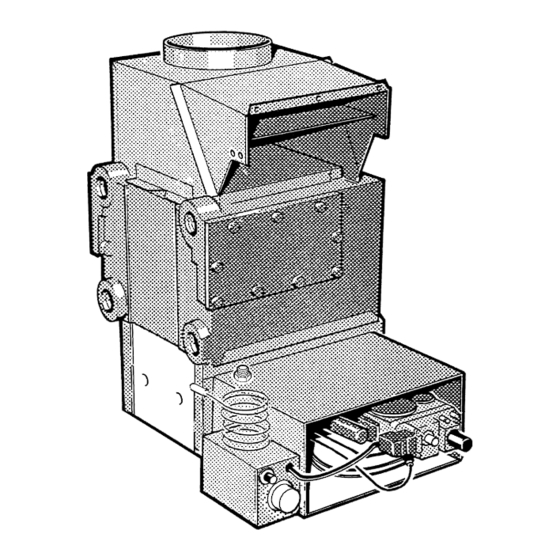
11 Spare Parts When spare parts are required apply to your local supplier. Please quote the name of the appliance, Glow-worm 56/2 BBU, also the serial number of the back boiler, to be found on the data label on the combustion chamber extension, see diagram 6.1. -
Page 24: Control Of Substances Hazardous To Health
Control of Substances Hazardous to Health Information for the Installer and Service Engineer. Under Section 6 of The Health and Safety at Work Act 1974, we are required to provide information on substances hazardous to health. The adhesives and sealants used in this appliance are cured and give no known hazard in this state. INSULATION PADS/CERAMIC FIBRE, GLASSYARN These can cause irritation to skin, eyes and the respiratory tract.
Need help?
Do you have a question about the 56/2 and is the answer not in the manual?
Questions and answers