Table of Contents
Advertisement
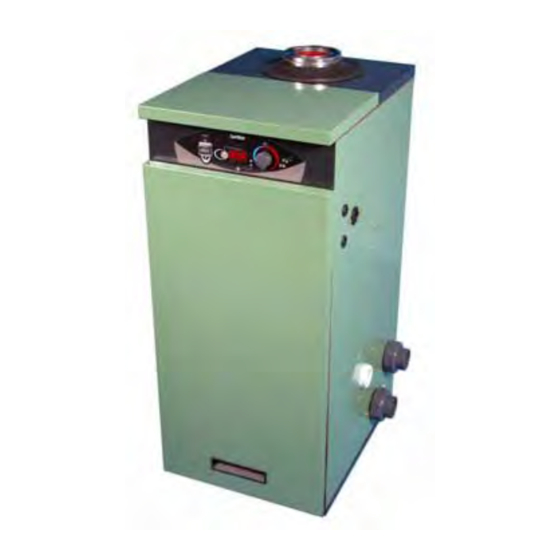
Factory set for Natural Gas.
Can be Converted to Propane
with parts provided.
WARNING: If the information in these instructions are not followed exactly, a fire or explosion
may result causing property damage, personal injury or death.
-
Do not store or use gasoline or other flammable vapours and liquids in the vicinity
of this or any other appliance.
-
WHAT TO DO IF YOU SMELL GAS
•
Do not try to light any appliance.
•
Do not touch any electrical switch; do not use any phone in your building.
•
Immediately call your gas supplier from a neighbour's phone. Follow the gas
supplier's instructions.
-
Installation and service must be performed by a Corgi registered installer.
Operating, Installation and
Servicing Instructions for
Condensing
Pool & Spa Heaters
Serial No:
Genie
Models:
MB35C
MB50C
M1996
Advertisement
Table of Contents

Related Manuals for Certikin MB35C


Summary of Contents for Certikin MB35C
- Page 1 Immediately call your gas supplier from a neighbour's phone. Follow the gas supplier's instructions. Installation and service must be performed by a Corgi registered installer. Genie Operating, Installation and Servicing Instructions for Models: MB35C Condensing MB50C Pool & Spa Heaters M1996...
-
Page 2: Technical Data
TECHNICAL DATA GENERAL SPECIFICATIONS WATER CONTENT MB35C 3.75 Litres 0.83 gallons MB50C 4.45 Litres gallons MAXIMUM WATER PRESSURE 5 bar (70 psi) MAXIMUM WATER FLOW TEMP Pool 32°C (90°F) Spa 41°C (106°F) ELECTRICAL SUPPLY 230V 50Hz, FUSED AT 3A, 130W... -
Page 3: Table Of Contents
Contents Section Page List of Figures Page TECHNICAL DATA Inside cover Fig 1.0 Terminal Positions Fig 2.0 Hydraulic Resistance Graph 5 User Instructions Fig 3.0 Service Access & Pipe Connections INTRODUCTION Fig 3.1 Wall Terminal Dimensions Heater Location Fig 3.2 Outdoor Terminal Dimensions Gas Supply Fig 3.3... - Page 4 Genie USER'S OPERATING INSTRUCTIONS FOR YOUR SAFETY - READ BEFORE OPERATING WARNING: IF YOU DO NOT FOLLOW THESE INSTRUCTIONS EXACTLY, A FIRE OR EXPLOSION MAY RESULT, CAUSING PROPERTY DAMAGE, PERSONAL INJURY OR LOSS OF LIFE. This appliance is equipped with an ignition device * Isolate the appliance with the Service which automatically lights the burner.
- Page 5 Pool Temperature Control Knob CAUTION Elevated water temperature can be hazardous, and 16°C to 32°C or 41°C (60°F to 90°F or 106°F) the U.S. Consumer Product Safety Commission (Maximum is changed in Setup Mode, see Page 11) recommends the following guidelines: Rotate clockwise to increase the Pool Temperature.
-
Page 6: Introduction
Health and Safety document No 635, “Electricity at INTRODUCTION Work Regulations”. Detailed recommendations are contained in the following British Standard Codes of Practice. These Instructions cover a range of direct, floor mounted, gas fired, condensing pool heaters which Codes of Practice. are room sealed and fan assisted. -
Page 7: Gas Supply
cannot be touched by a person using the bath or Terminal Position Minimum shower. Where installation will be in an unusual location then Below window or vent 300 mm special procedures may be necessary and BS.6798 Below gutter or pipes 75 mm gives detailed guidance on this aspect. -
Page 8: Condensate Drain 5 Fig
Genie Resistance - - - - - - Genie 35 Fig. 2.0 Genie 50 Condensate Drain Winterisation See Fig. 7.0, and 7.1 Turn off the Mains electricty and Gas Supply. Draining the Heater can be achieved by the opening A 75mm condensate trap is provided on the Heater of an unused pool connection. -
Page 9: Installation Of Heater
Assembly INSTALLATION OF HEATER All items assemble by a push fit/clamp system. If it is required to lubricate the seals only Centra Cerin supplied by the manufacturer or Silicone Grease Space Required for Installation and Service. should be used. The pipes should be assembled so the socket end is Left, Right or Above 300 mm 12 in. -
Page 10: Wall Terminal Dimensions
Heater Dimensions Pipe Connections & Locations Fig. 3.0 Dimensions Model lh side rh side Genie 35 165mm 385mm 252mm 270mm Genie 50 197mm 449mm Service Access Connections Multi Heater Connection Left, Right or Above 300mm In Front 800mm External Control (CCP01) -
Page 11: Outdoor Terminal Dimensions
Outdoor Flue Terminal Outdoor Terminal (MBOT) Dimensions Clamp Assembly Screw Fig. 3.2 Vertical Roof Terminal Dimensions Flat Roof Pitched Roof Installation Installation Use Seldeck Flashing System for all Roof Installations Vertical Roof Terminal (MBVT) 1 metre Horizontal/ Vertical Extension Pipe (MBHVE) 45 degree bends (MB45DB) -
Page 12: Flue Examples
Flue Examples Extended Horizontal Extended Vertical Outdoor Terminal Wall Terminal Roof Terminal MBOT MB90DB MBHVE MBHT (not shown) MBVT MBHVE TO OFFSET USE MB45DB TO OFFSET USE MB45DB Fig.4.3 Horizontal Wall Terminal MB90DB MBHT (not shown) Fig.4.1 Fig.4.2 Fig.4.0 Flue Kit Part Codes Determine the type of Flue system you require and choose from the list of kits available below: Type of Flue System... - Page 13 Flue Kit Part Codes (cont.) The Maximum Flue Equivalent Length (FEL) permitted is 20 metres, horizontal or vertical. The Flue Kits available below list the FEL for each component. Add up all the FEL’s used in your design and check that this does not exceed 20 metres.
-
Page 14: Fig. 5.0
Flue Parts Assembly Outdoor Terminal All items assemble by a push fit/clamp system. If it is A specific Outdoor Top Terminal must be used required to lubricate the seals only Centra Cerin for an outdoor installation. supplied by the manufacturer or Silicone Grease The Outdoor Top Terminal is a push fit into the Flue should be used. -
Page 15: Pressure Switch
Plumbing The heater requires water flow and pressure to operate properly. It must therefore be installed downstream of the filter and pump. A typical installation is plumbed as follows: 1. The Pump outlet is plumbed to the inlet of the Filter. 2. -
Page 16: Fig. 6.0
Condensate Connection Throttle The direction of the plastic condensate drain pipe Adjustment connection can be altered from the factory position on the left, to the right. Remove the blanking plate from the left hand side (See Fig. 3.1) Loosen the two screws holding the Trap bracket and swivel the trap through 90 degrees. -
Page 17: Condensate Disposal
Example Condensate Disposal Methods Note: Do not reduce the pipe size below the 40mm provided. Soakaway 200mm Land Drain Filled with Lime Stack Attachment chippings 400mm Insulate against deep freezing Strap-On Boss 1:20 Fall ( 2.5 Degrees ) Soil Pipe or Fig.7.0 Drain Condensate Syphon (75 mm) -
Page 18: Electrical Connection Fig
The boiler is fitted with automatic ignition and will start when the gas cock is open, mains is connected Electrical Connections and the Pressure Switch is activated by the pool WARNING: The appliance MUST be earthed. Pump. (for greater detail about the internal controls see the Maintenance section, Fault Diagnosis) If the Heater fails to light the gas it will shutdown and All wiring for the Heater and system controls MUST... -
Page 19: Control Setup
Genie Fig. 9.0 Setting Temperature Pool Temperature Lock/Reset On / Off Position Display Setting Knob Button Switch Setup Mode Setting Factory Setting Alternative Display Indicator Display units ° F = Fahrenheit ° C = Centigrade ° F or ° C Maximum temperature 32 °C (90 °F) -
Page 20: Multiple Heater Kit
Installation Instructions Multiple Heater Kit Disconnect the Heater from the Mains then Overview remove the Top Panel and the Electrical Chassis Cover. It is possible to connect together several Heaters and by doing so obtain a larger output with an Remove Pool Thermostat Control Knob economical and a fail-safe design. - Page 21 Operation Turn on all the Heaters with their Pool Tempera ture Controls. The Master will show temperatures and the Slaves “---”. Set the required temperature on the Master and provided there is an electrical demand at the Master’s Pool Demand connection, the Heaters will run.
-
Page 22: Schematic Wiring
Schematic Wiring X12.16 MODULATION -ve X12.14 X12.13 FAN -ve X12.12 HI LIMIT X12.11 FAN +ve X12.10 RESET -ve X12.8 MODULATION +ve CVBC X12.5 FAN PWM X12.4 X12.3 HI LIMIT X12.2 RESET +ve X12.1 FAN TACHO Blue Black X1.10 Brown X1.9 240v 3 Wire Green/Yellow X1.8... -
Page 23: Fault Finding
FAULT FINDING WARNING: BEFORE COMMENCING OR COMPLETING ANY ELECTRICAL WORK ON THE APPLIANCE, IT IS RECOMMENDED THAT THE BASIC SAFETY CHECKS FOR EARTH CONTINUITY, SHORT CIRCUIT, POLAR- ITY AND RESISTANCE TO EARTH ARE MADE. ALL WORK CARRIED OUT SHOULD FOLLOW GUIDELINES LAID DOWN BY THE I.E.E. -
Page 24: Display Fault Codes
Fault Codes LED2 LED1 YELLOW GREEN Condensing Pool Heater 14/11/06... - Page 25 Fault Codes LED2 LED1 YELLOW GREEN Condensing Pool Heater 14/11/06...
-
Page 26: Servicing
Pipework SERVICING IMPORTANT. The Heat Exchanger connections are made using O rings and retaining clamps and should not be strained in any direction. Any strain will result Health and Safety Statement : in damage to the Heat Exchanger and will not be This Heater contains no asbestos. -
Page 27: Heater Components
Transformer Heat Exchanger Combustion (See Fig. 12.0) The Transformer includes its own, internal thermal Temperature Sensor fuse on the primary. If this has gone open circuit the This is located on the top of the Heat Exchanger, on cause should be established before replacing the the right hand side. - Page 28 Venturi (See Fig.13.2) Remove the Ignition Control and Gas Valve, see above. Pull off the Air Tube (See Fig.13.3) Undo the two screws holding the Venturi to the Fan and remove. Ensure the gasket is transferred to the new venturi or positioned on the Fan before positioning the replacement.
-
Page 29: Spares
Spares 1st Line Spares: Item Part Number SPMBG Primary Heat Exchanger (35 kW) M2136 SPMBG001 Primary Heat Exchanger (50 kW) M2139 SPMBG002 Propane Orifice 35kW M2150 SPMBG014 Propane Orifice 50kW M2151 SPMBG015 M2138 SPMBG003 Gas Valve M2140 SPMBG004 Ignition Control M2141 SPMBG005 Pool Thermostat PCB... -
Page 30: Heater Components
Heater Components Combustion Flue Adapter Flue Thermostat Sample Point Fig.13.1 Heat Exchanger Condensate Combustion Pressure Temp Sensor Switch Heat Exchanger Spark & Sense Electrode Fig.13.2 Fixing Nuts Venturi Fan Electrical Connectors Air Tube Condensate Syphon Fig.13.3 Venturi Throttle Offset Tube Gas Valve HT Lead Fig.13.0... - Page 31 Station Lane Industrial Estate Witney Oxon. Tel. 01993 778855 Fax. 01993 703407 22/11/06...
Need help?
Do you have a question about the MB35C and is the answer not in the manual?
Questions and answers