Table of Contents
Advertisement
Quick Links
Advertisement
Table of Contents

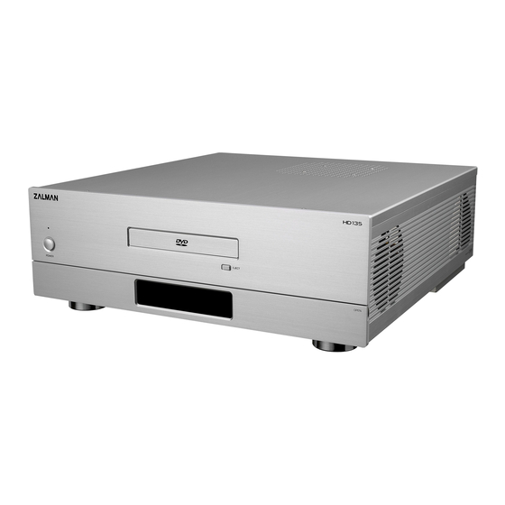
Summary of Contents for ZALMAN HD135
- Page 1 Ver. 1.0...
- Page 2 HD135 English Please read this manual thoroughly before installation. Visit our website and watch the HD135 installation video first to assist you in the installation process. E-mail: zalman@zalman.co.kr w w w. z a l m a n . c o . k r...
-
Page 3: Table Of Contents
9. Zalman Enclosures ........ -
Page 4: Safety Notices
Disclaimer Zalman Tech Co., Ltd. is not responsible for any damages due to external causes, including but not limited to, improper use, problems with electrical power, accident, neglect, alteration, repair, improper installation, or improp- er testing. -
Page 5: Components
HD135 3. Components 1) HD135 Body Top Cover Fan & Air Duct ODD Bracket Bracket Bracket External Body Drive Cover 2) Case Parts 1 ODD Aluminum Bezel 24 HDD / Power Supply Bolts (PH #6-32X6) 24 ODD / FDD / Motherboard... -
Page 6: Features
HD135 4. Features 1) Optimized Design for Silence A. Designed for High TDP Processors: Air Duct and two Fans allow quiet cooling of up to 130W TDP CPU processors (Intel Pentium D 830, 840, 940, 950, 960 etc.). B. Designed for High Performance Power Supply:... - Page 7 5) Ideal Home Theatre PC A quiet and stable Home Theatre PC can be assembled when used with Zalman's CPU Cooler, VGA Cooler, Power Supply, and Northbridge Cooler (CNPS8000, VF700, VF900, ZM460B-APS, ZM-NBF47 etc.). The specifications of any product may change without prior notice to improve performance.
-
Page 8: Specifications
HD135 5. Specifications ½ Enclosure Type - Desktop ½ Dimensions (LXWXH) - 435mm X 425mm X 135mm (17.1inch X 16.7inch X 5.31inch) ½ Weight - 5.2kg (11.5lb) ½ Material - Aluminum ½ Motherboard Compatibility - ATX / microATX ½ Power Supply Support - ATX / ATX 12V ½... -
Page 9: Installation Guide
HD135 6. Installation Guide 1) Opening the Enclosure To remove the lid of the enclosure, unscrew the two Bolts (Finger Bolt, #6-32) and slide backwards and lift the Top Plate as shown in the figure below. TOP Plate Finger Bolt... - Page 10 HD135 3) Assembling the Motherboard and Power Supply Mount the motherboard and power supply by using appropriate bolts. Mount the computer components (CPU, VGA, RAM etc.) onto the motherboard. Bolt (PWH M3x5) Power Supply Motherboard Bolt (PH #6-32X6) Note) 1. To mount a microATX motherboard, first attach the two provided microATX Standoffs and align them with the height of the ATX Standoffs.
- Page 11 HD135 4) Installing 5.25" and 3.5" Drives (1) To install the FDD and Card Reader onto HDD Bracket, the External Drive Cover assembled on the Front Plate must first be removed. (2) Attach the 5.25" drive (ODD) and 3.5" drive (HDD, FDD, Card Reader) onto the ODD and HDD Brackets with the use of appropriate Bolts.
- Page 12 HD135 5) Deciding on Air Duct Location Install the Air Duct connected to the Top Plate right above the CPU cooler for optimal CPU cooling. Top Plate Air Duct Note) CPU cooler performance will drastically decrease if the installation is made without the Air Duct.
- Page 13 HD135 (3) Front I/O Cable Connect the USB Cable, 1394(Fire Wire) Cable, and Audio Cable to the moth- erboard as explained in the motherboard manual. The specifications of any product may change without prior notice to improve performance.
- Page 14 HD135 (4) VFD Multi-Cable Connect the VFD Power Connector to the Power Supply Connector. Connect the VFD USB Connector to the motherboard's USB Port. Front Plate inside View Power Supply VFD Power Connector Connector Motherboard USB Port VFD USB Connector Note) 1.
- Page 15 HD135 Place the Temperature Sensor on a place of preference inside the Enclosure. Connect the Motherboard Power Connector to the motherboard's Front Panel Port (refer to the motherboard manual). Connect the Fan Connector to the Fan installed on the Top Cover, and assemble the Top Cover.
- Page 16 HD135 7) Attaching the Aluminum ODD Bezel (1) Connect power to the assembled system. Press the ODD Eject button to eject the ODD Tray. (2) Remove the plastic ODD Bezel. (3) Expose the Tape Film on the inside of the aluminum ODD bezel, and stick the aluminum ODD bezel to the ODD tray.
-
Page 17: Recommended Use
(main factor of noise emission) will also significantly decrease due to better cool- ing efficiency. There must be good airflow on the front and back side of the HD135 when plac- ing it inside a cabinet. Any other AV components or products must not be placed on top of the HD135. - Page 18 : VGA card equipped with a silent VGA cooler ½ VGA Cooler : Silent VGA cooler ½ Power Supply : Power Supply equipped with a 120mm fan(HD135 is provided with an Air Vent for power supplies equipped with a 120mm Fan).
-
Page 19: Technical Information
VGA Card : Evertop Geforce7800GT 256MB Power Supply : ZM460-APS This information is for reference purpose only. Zalman is not guaranteeing any performance result with the setup of the Test System. The specifications of any product may change without prior notice to improve performance. -
Page 20: Zalman Enclosures
All trademarks mentioned in this manual are properties of their respective owners. - ZALMAN and HD135 are registered trademarks of ZALMAN Tech Co., Ltd. - Intel and Pentium D are registered trademarks of Intel Corp. - VGA are registered trademarks of International Business Machines Corporation (IBM).


Need help?
Do you have a question about the HD135 and is the answer not in the manual?
Questions and answers