
Related Manuals for ZALMAN GS1000


Summary of Contents for ZALMAN GS1000
- Page 1 GS1000 English version ◈ Please read this manual thoroughly before installation. ◈ Please visit the GS1000 web page at Zalman’ s website to view the GS1000 installation video. E-mail: zalman@zalman.com www.zalman.com...
-
Page 2: Table Of Contents
GS1000 ▣ Contents 1. Cautionary Notes 2. Specifications 3. Parts List 4. Installation 5. Options 6. Quality Assurance and Warranty Information... -
Page 3: Cautionary Notes
9) The specifications of any product may change without prior notice to improve performance Disclaimer) Zalman Tech Co., Ltd. is not responsible for any damages due to extemal causes, including but not limited to, improper use, problems with electrical power, accident, neglect, alternation,... -
Page 4: Specifications
GS1000 2 Specifications Type Full Tower Dimensions 640mm x 260mm x 570mm (including feet) (D x W x H) (25.2 x 10.2 x 22.4 ) Weight 14.4kg (27.5lb) Material(s) Aluminum / ABS / Steel Color Options Black / Titanium Motherboard Compatibility... -
Page 5: Parts List
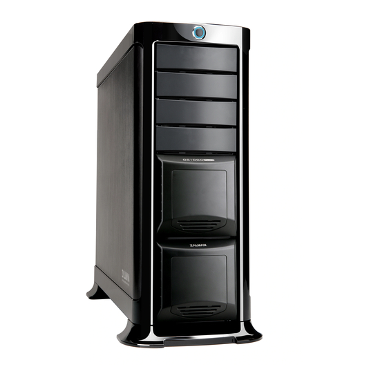
GS1000 3 Parts List 1) GS1000 POWER USB 2.0 Headphones IEEE 1394 Front View Rear View Top View Side View... - Page 6 GS1000 2) GS1000 Blow-Up Diagram ⑤ ⑦ ⑧ ④ ③ ⑨ ② ⑩ ① ⑪ Part No. Part Name Part No. Part Name HDD Cover Side Panel HDD Tray PSU Bracket “2 in 1” Bracket PSU Fan Bracket 5.25 " Bay Cover...
- Page 7 GS1000 3) GS1000 Parts Diagram Part Name Role Foot (Front/Rear) Support CPU 12V CPU Power Extension Extension Cable Cable microATX M/B Installation M/B Stand Off (silver) HDD Screws HDD Installation (black) PSU, Motherboard PSU Screws Installation (black) Foot Fixing Screws...
-
Page 8: Installation
GS1000 4 Installation 1) Feet Assembly Front Foot Rear Foot Foot Fixing Screw 2) Side Panel Removal... - Page 9 GS1000 3) PSU Installation (1) PSU Bracket Removal PSU Screw A Type B Type (2) PSU Bracket Assembly A Type B Type ▶A Type : Please position the PSU’s intake facing downwards to optimize PSU cooling. ▶B Type : Please position the PSU’s intake facing upwards to optimize system cooling.
- Page 10 GS1000 4) Motherboard Installation M/B Stand Off PSU Screw micro ATX motherboard Server motherboard ※ When installing a micro ATX or server motherboard, please install the M/B Stand Offs as shown in the diagram. 5) Hot Swap HDD Installation " " HDD Removal (1) 3.5...
- Page 11 GS1000 (2) HDD Tray HDD installation Push the Hooks located on the underside Diagram of “open” HDD Tray of the HDD Tray and push in the direction as shown above. Please check that the Tray’s metal pins are aligned with the HDD's fixing holes.
- Page 12 GS1000 ˝ ˝ Drive Installation 6) 5.25 (1) ODD Installation (2) FDD Installation (3) HDD Installation (additional HDD installation in a 5.25 bay)
- Page 13 GS1000 7) Hot Swap S-ATA Port 4-Pin Power Port Rear Front S-ATA Cable 4-Pin Power Cable Hot Swap PCB (1) Connect the Motherboard and Hot Swap PCB with the S-ATA cable. (2) Connect the 4-Pin Power Cable to the Hot Swap PCB.
-
Page 14: Options
GS1000 8) Front I/O Cable Connection For USB 2.0, IEEE1394a, and audio components, please refer to the motherboard's manual. Caution ※ Mixing the IEEE1394a and USB2.0 cables can cause severe damage to the system. ※ The Power LED will not function properly if connected with the wrong polarity (+/-). - Page 15 GS1000 2) Optional Bottom Panel 120mm Fan Installation Bottom Panel Center Fan Installation Bottom Panel Rear Fan Installation...
- Page 16 MEMO...
Need help?
Do you have a question about the GS1000 and is the answer not in the manual?
Questions and answers