
Subscribe to Our Youtube Channel
Related Manuals for National Instruments PXI-1042Q


Summary of Contents for National Instruments PXI-1042Q
- Page 1 National Instruments PXI-1042Q Manual Get Pricing & Availability at ApexWaves.com Call Today: 1-800-915-6216 Email: sales@apexwaves.com https://www.apexwaves.com/modular-systems/national-instruments/pxi-chassis/PXI-1042Q...
- Page 2 NI PXI-1042 Series User Manual NI PXI-1042 Series User Manual April 2004 Edition Part Number 371088A-01...
- Page 3 Thailand 662 992 7519, United Kingdom 44 0 1635 523545 For further support information, refer to the Technical Support and Professional Services appendix. To comment on the documentation, send email to techpubs@ni.com. © 2002–2004 National Instruments Corporation. All rights reserved.
- Page 4 The reader should consult National Instruments if errors are suspected. In no event shall National Instruments be liable for any damages arising out of or related to this document or the information contained in it.
-
Page 5: Table Of Contents
Installing Slot Blockers ...................2-3 Rack Mounting ......................2-3 Connecting Safety Ground.....................2-3 Connecting to Power Source..................2-4 Installing a PXI Controller.....................2-4 Installing PXI Modules ....................2-6 Power Switch LED Indicator ..................2-8 Remote Voltage Monitoring and Control ..............2-8 © National Instruments Corporation NI PXI-1042 Series User Manual... - Page 6 Contents PXI_CLK10 Rear Connectors..................2-10 10 MHz REF IN ....................2-10 10 MHz REF OUT..................2-10 Using System Configuration and Initialization Files ............ 2-11 Chapter 3 Maintenance Service Interval......................3-1 Preparation........................3-1 Cleaning......................... 3-2 Interior Cleaning ..................... 3-2 Exterior Cleaning .................... 3-2 Cleaning and Replacing the Fan Filters.................
-
Page 7: About This Manual
PXI-1042/PXI-1042Q The PXI-1042 chassis appears in the views throughout the manual. The mechanical features are identical between the PXI-1042 and the PXI-1042Q chassis unless otherwise noted. © National Instruments Corporation NI PXI-1042 Series User Manual... -
Page 8: Related Documentation
About This Manual Related Documentation The following documents contain information that you might find helpful as you read this manual: • Compact PCI Specification PICMG 2.0 R 3.0 • PXI Specification, Revision 2.0 • IEEE 1101.1-1991, IEEE Standard for Mechanical Core Specifications for Microcomputers Using IEC 603-2 Connectors •... -
Page 9: Getting Started
What You Need to Get Started The PXI-1042 Series kit contains the following items: ❑ PXI-1042 or PXI-1042Q chassis ❑ Filler panels ❑ AC power cable (refer to Table 1-1 for AC power cables) ❑... -
Page 10: Key Features
United Kingdom 230 V BS 1363/IEC83 If you are missing any of the items listed in Table 1-1, or if you have the incorrect AC power cable, contact National Instruments. Key Features The PXI-1042 Series combines a high-performance 8-slot PXI backplane with a high-output power supply and a structural design that has been optimized for maximum usability in a wide range of applications. -
Page 11: Chassis Description
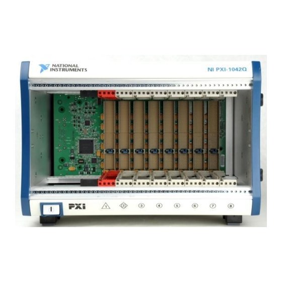
Figure 1-1 shows the front view of the PXI-1042. Figure 1-2 shows the rear view of the PXI-1042. Figure 1-3 shows the rear view of the PXI-1042Q. NI PXI-1042 1 Backplane Connectors (Located in Slots 1–8) - Page 12 Chapter 1 Getting Started 1 Circuit Breaker 7 10 MHz REF IN BNC 2 Universal AC Inlet 8 Metal Filter Cover 3 Chassis Ground Screw 9 Power-Supply Shuttle Captive Screw 4 Fan Speed Selector Switch 10 Power-Supply Shuttle 5 10 MHz REF OUT BNC 11 Filter Retainer Screw 6 Remote Inhibit and Voltage Monitoring Connector Figure 1-2.
-
Page 13: Optional Equipment
6 Remote Inhibit and Voltage Monitoring Connector Figure 1-3. Rear View of the PXI-1042Q Chassis Optional Equipment Contact National Instruments to order the following options for the PXI-1042 Series chassis. EMC Filler Panels Optional EMC filler panel kits are available from National Instruments. -
Page 14: Slot Blockers
PXI-1042 Series Chassis Rack Mount Kit Components. Slot Blockers Optional slot blocker kits are available from National Instruments for improved thermal performance when all slots are not used. PXI-1042 Series Backplane Overview Interoperability with CompactPCI The PXI-1042 Series backplane is interoperable with PXI-compatible products and standard CompactPCI products. -
Page 15: Star Trigger Slot
Local bus signals may range from high-speed TTL signals to analog signals as high as 42 V. Initialization software uses the configuration information specific to each adjacent peripheral module to evaluate local bus compatibility. © National Instruments Corporation NI PXI-1042 Series User Manual... -
Page 16: Trigger Bus
Chapter 1 Getting Started Star Triggers Local Local Local PCI Arbitration and Clock Signals Figure 1-4. PXI Local Bus and Star Trigger Routing Trigger Bus All slots share eight trigger lines. You can use these trigger lines in a variety of ways. - Page 17 10 MHz REF IN connector on the rear of the chassis, the signal on the Star Trigger Slot is selected and provided to all peripheral slots and the external 10 MHz REF OUT connector on the rear of the chassis. © National Instruments Corporation NI PXI-1042 Series User Manual...
-
Page 18: Installation And Configuration
When rack mounting a PXI-1042 Series chassis, provide 1.75 in. (44.5 mm) clearance above and on the sides of the unit for adequate venting. High-power applications may require additional clearance. © National Instruments Corporation NI PXI-1042 Series User Manual... -
Page 19: Setting Fan Speed
Refer to Figure 1-2, Rear View of the PXI-1042 Chassis, and Figure 1-3, Rear View of the PXI-1042Q Chassis, to locate the fan-speed selector switch. Select HIGH for maximum cooling performance (recommended) or AUTO for quieter operation. When set to AUTO, the fan speed is determined by chassis intake air temperature. -
Page 20: Installing Slot Blockers
Rack Mounting Rack mount applications require the optional rack mount kits available from National Instruments. Refer to the instructions supplied with the rack mount kits to install your PXI-1042 Series in an instrument rack. Refer to Figure A-3, PXI-1042 Series Chassis Rack Mount Kit Components. -
Page 21: Connecting To Power Source
AC power cable supplied. Refer to Figure 1-2, Rear View of the PXI-1042 Chassis, and Figure 1-3, Rear View of the PXI-1042Q Chassis, to locate the AC inlet. The power switch allows you to power on the chassis or place it in standby mode. - Page 22 Figure 2-3 shows a PXI controller installed in the system controller slot of a PXI-1042 chassis. You can place CompactPCI or PXI modules in any other slot. © National Instruments Corporation NI PXI-1042 Series User Manual...
-
Page 23: Installing Pxi Modules
Chapter 2 Installation and Configuration 1 PXI-1042 Chassis 2 NI Controller 3 Injector/Ejector Rail Figure 2-3. NI Controller Installed in a PXI-1042 Chassis Installing PXI Modules Caution Disconnect the AC power cable before installing CompactPCI or PXI modules. To install a module, complete the following steps: Install a module into a chassis slot by first placing the module card edges into the front module guides (top and bottom), as shown in Figure 2-4. - Page 24 1 PXI-1042 Series Chassis 4 Injector/Ejector Handle 2 NI Controller 5 Injector/Ejector Rail 3 PXI Module Figure 2-4. Installing PXI or CompactPCI Modules © National Instruments Corporation NI PXI-1042 Series User Manual...
-
Page 25: Power Switch Led Indicator
Chapter 2 Installation and Configuration Power Switch LED Indicator The chassis power switch has an integrated LED. This LED indicates one of three different conditions: • If the power switch LED is steady green (not flashing), the chassis is powered on and operating normally. •... - Page 26 +12 V 11.4 to 12.6 V –12 V –12.6 to –11.4 V 1, 9 Logic Ground If the voltages fall within the specified ranges, the chassis complies with the CompactPCI voltage-limit specifications. © National Instruments Corporation NI PXI-1042 Series User Manual...
-
Page 27: Pxi_Clk10 Rear Connectors
Chapter 2 Installation and Configuration PXI_CLK10 Rear Connectors There are two BNC connectors on the rear of the PXI-1042 Series chassis for PXI_CLK10. The connectors are labeled IN and OUT. You can use them for supplying the backplane with PXI_CLK10 or routing the backplane’s PXI_CLK10 to another chassis. -
Page 28: Using System Configuration And Initialization Files
The device drivers should have no need to directly read the file. For detailed information regarding chassis.ini initialization files, refer to the PXI specification at www.pxisa.org © National Instruments Corporation 2-11 NI PXI-1042 Series User Manual... -
Page 29: Maintenance
Service the chassis only in a static-free environment. Observe standard handling precautions for static-sensitive devices while servicing the chassis. Always wear a grounded wrist strap or equivalent while servicing the chassis. © National Instruments Corporation NI PXI-1042 Series User Manual... -
Page 30: Cleaning
To remove the filter retainer, loosen the retainer screw. The filter cover and retainer are shown in Figure 1-2, Rear View of the PXI-1042 Chassis, and Figure 1-3, Rear View of the PXI-1042Q Chassis. NI PXI-1042 Series User Manual ni.com... -
Page 31: Resetting The Ac Mains Circuit Breaker
Chapter 2, Installation and Configuration. If the power switch LED is not a steady green, contact National Instruments. Verify that the PXI-1042 Series can meet the power requirements of your CompactPCI or PXI modules. Overloading the chassis can cause the breaker to trip. -
Page 32: Replacing The Modular Power Supply
This section describes how to remove, configure, and install the AC power-supply shuttle in the PXI-1042 Series chassis. Note The AC power supply shuttles for the PXI-1042 and PXI-1042Q chassis are not interchangeable. Disconnect the power cable prior to replacing the power supply. -
Page 33: Configuration
Refer to Figure 1-2, Rear View of the PXI-1042 Chassis, and Figure 1-3, Rear View of the PXI-1042Q Chassis, to locate the fan-speed selector. Select HIGH for maximum cooling performance (recommended) or AUTO for quieter operation. When set to AUTO, air-intake temperature determines the fan speed. -
Page 34: Appendix A Specifications
DC power to the CompactPCI/PXI backplane. You also can use the rear-panel D-SUB 9-pin connector to control the internal chassis power supply. The operating range is guaranteed by design. © National Instruments Corporation NI PXI-1042 Series User Manual... - Page 35 Appendix A Specifications DC Output DC current capacity (I PXI-1042 PXI-1042Q Voltage 0–50 °C 0–55 °C 0–40 °C +3.3 V 20 A 18 A 20 A +5 V 29 A 25 A 29 A +12 V Peripheral slots 3.5 A 3.5 A...
- Page 36 PXI-1042......... Forced air circulation (positive pressurization) through two 60 cfm fans with HIGH/AUTO speed selector PXI-1042Q........Forced air circulation (positive pressurization) through two 51 cfm fans with HIGH/AUTO speed selector Slot airflow direction ......P1 to P2, bottom of module to top of module Module cooling intake ......
- Page 37 Pollution Degree ........2 Operating Environment Ambient temperature range PXI-1042 ..........0 to 55 °C (Tested in accordance with IEC-60068-2-1 and IEC-60068-2-2.) PXI-1042Q..........0 to 40 °C (Tested in accordance with IEC-60068-2-1 and IEC-60068-2-2.) Relative humidity range......10 to 90%, noncondensing (Tested in accordance with IEC-60068-2-56.) Storage Environment Ambient temperature range ....–20 to 70 °C (Tested in...
- Page 38 (Tested in accordance with ISO 7779.) PXI-1042Q Auto fan (at 25 °C ambient).... 52.2 dBA High fan .......... 62.4 dBA PXI-1042 Auto fan (at 25 °C ambient).... 58.8 dBA High fan .......... 67.7 dBA © National Instruments Corporation NI PXI-1042 Series User Manual...
- Page 39 Appendix A Specifications Safety The PXI-1042 Series chassis were evaluated using the criteria of EN 61010-1 and meets the requirements of the following standards for safety and electrical equipment for measurement, control, and laboratory use: • EN 61010-1, IEC 61010-1 •...
- Page 40 Input frequency ....... 10 MHz ±100 ppm or better Input amplitude Rear connector ......200 mV to 5 V , 10 MHz squarewave or sinewave Slot 2........5 V or 3.3 V, 10 MHz TTL signal © National Instruments Corporation NI PXI-1042 Series User Manual...
- Page 41 Appendix A Specifications Input impedance ......50 Ω ± 5 Ω (rear connector) Maximum jitter introduced by backplane circuitry .....1 ps RMS in 10 Hz to 1 MHz range External clock output Connector ........BNC on rear of chassis (ground-referenced) ±20% squarewave into 50 Ω Output amplitude ......1 V into open circuit Output impedance......50 Ω...
- Page 42 1.68 12.334 [313.38] [42.7] 1.823 1.40 [46.30] [35.6] 1.844 3.542 Front of [46.84] [89.97] PXI Card 2.13 8X, M4 [54.1] 15.61 [396.5] Figure A-1. PXI-1042 Series Chassis Dimensions (Front and Side) © National Instruments Corporation NI PXI-1042 Series User Manual...
- Page 43 Appendix A Specifications 1.01 [25.7] 12.700 [322.58] 1.02 [25.8] 8.65 [219.7] 4X, M4 Figure A-2. PXI-1042 Series Chassis Dimensions (Bottom) NI PXI-1042 Series User Manual A-10 ni.com...
- Page 44 Figure A-3 shows the PXI-1042 Series chassis rack mount kit components. 1 Front Rack Mount Kit 2 PXI-1042 Series Chassis 3 Optional Rear Rack Mount Kit Figure A-3. PXI-1042 Series Chassis Rack Mount Kit Components © National Instruments Corporation A-11 NI PXI-1042 Series User Manual...
-
Page 45: Appendix B Pinouts
Table B-6 shows the P2 (J2) connector pinout for the peripheral slots. PXI signals are shown in boldface. Note For more detailed information, refer to the PXI Specification, Revision 2.0. Contact the PXI Systems Alliance for a copy of the specification. © National Instruments Corporation NI PXI-1042 Series User Manual... - Page 46 Appendix B Pinouts Table B-1. P1 (J1) Connector Pinout for the System Controller Slot REQ64# ENUM# 3.3V AD[1] V(I/O) AD[0] ACK64# 3.3V AD[4] AD[3] AD[2] AD[7] 3.3V AD[6] AD[5] 3.3V AD[9] AD[8] M66EN C/BE[0]# AD[12] V(I/O) AD[11] AD[10] 3.3V AD[15] AD[14] AD[13] SERR#...
- Page 47 AD[54] AD[53] AD[59] V(I/O) AD[58] AD[57] AD[63] AD[62] AD[61] AD[60] C/BE[5]# V(I/O) C/BE[4]# PAR64 V(I/O) PXI_BRSVB4 C/BE[7]# C/BE[6]# CLK4 GNT3# REQ4# GNT4# CLK2 CLK3 SYSEN# GNT2# REQ3# CLK1 REQ1# GNT1# REQ2# © National Instruments Corporation NI PXI-1042 Series User Manual...
- Page 48 Appendix B Pinouts Table B-3. P1 (J1) Connector Pinout for the Star Trigger Slot REQ64# ENUM# 3.3V AD[1] V(I/O) AD[0] ACK64# 3.3V AD[4] AD[3] AD[2] AD[7] 3.3V AD[6] AD[5] 3.3V AD[9] AD[8] M66EN C/BE[0]# AD[12] V(I/O) AD[11] AD[10] 3.3V AD[15] AD[14] AD[13] SERR#...
- Page 49 AD[55] AD[54] AD[53] AD[59] V(I/O) AD[58] AD[57] AD[63] AD[62] AD[61] AD[60] C/BE[5]# V(I/O) C/BE[4]# PAR64 V(I/O) PXI_BRSVB4 C/BE[7]# C/BE[6]# PXI_LBR7 PXI_LBR8 PXI_LBR9 PXI_LBR10 PXI_LBR11 PXI_LBR12 PXI_STAR7 PXI_STAR8 PXI_STAR9 PXI_STAR10 PXI_STAR11 PXI_STAR12 © National Instruments Corporation NI PXI-1042 Series User Manual...
- Page 50 Appendix B Pinouts Table B-5. P1 (J1) Connector Pinout for the Peripheral Slot REQ64# ENUM# 3.3V AD[1] V(I/O) AD[0] ACK64# 3.3V AD[4] AD[3] AD[2] AD[7] 3.3V AD[6] AD[5] 3.3V AD[9] AD[8] M66EN C/BE[0]# AD[12] V(I/O) AD[11] AD[10] 3.3V AD[15] AD[14] AD[13] SERR# 3.3V...
- Page 51 AD[55] AD[54] AD[53] AD[59] V(I/O) AD[58] AD[57] AD[63] AD[62] AD[61] AD[60] C/BE[5]# V(I/O) C/BE[4]# PAR64 V(I/O) PXI_BRSVB4 C/BE[7]# C/BE[6]# PXI_LBR7 PXI_LBR8 PXI_LBR9 PXI_LBR10 PXI_LBR11 PXI_LBR12 PXI_LBL7 PXI_LBL8 PXI_LBL9 PXI_LBL10 PXI_LBL11 PXI_LBL12 © National Instruments Corporation NI PXI-1042 Series User Manual...
- Page 52 Technical Support and Professional Services Visit the following sections of the National Instruments Web site at for technical support and professional services: ni.com • Support—Online technical support resources at ni.com/support include the following: – Self-Help Resources—For immediate answers and solutions,...
- Page 53 Appendix C Technical Support and Professional Services If you searched and could not find the answers you need, contact ni.com your local office or NI corporate headquarters. Phone numbers for our worldwide offices are listed at the front of this manual. You also can visit the Worldwide Offices section of to access the branch ni.com/niglobal...
- Page 54 Symbols ° Degrees. ≥ Equal or greater than. ≤ Equal or less than. Percent. Amperes. Alternating current. ANSI American National Standards Institute. AUTO Automatic fan speed control. American Wire Gauge. © National Instruments Corporation NI PXI-1042 Series User Manual...
- Page 55 Glossary backplane An assembly, typically a printed circuit board, with connectors and signal paths that bus the connector pins. Bayonet Neill Concelman connector; a commonly used coaxial connector. Celsius. Cubic feet per minute. Code of Federal Regulations. Centimeters. CompactPCI An adaptation of the Peripheral Component Interconnect (PCI) Specification 2.1 or later for industrial and/or embedded applications requiring a more robust mechanical form factor than desktop PCI.
- Page 56 Hours. Hertz; cycles per second. International Electrotechnical Commission; an organization that sets international electrical and electronics standards. IEEE Institute of Electrical and Electronics Engineers. Mainframe peak current. © National Instruments Corporation NI PXI-1042 Series User Manual...
- Page 57 Glossary Inches. inhibit To turn off. jitter A measure of the small, rapid variations in clock transition times from their nominal regular intervals. Units: seconds RMS. Kilograms. Kilometers. Pounds. Light emitting diode. line regulation The maximum steady-state percentage that a DC voltage output will change as a result of a specified change in input AC voltage (step change from 90 to 132 VAC or 180 to 264 VAC).
- Page 58 This slot is located at Slot 2 and has a dedicated trigger line between each peripheral slot. Use this slot for a module with ST functionality that can provide individual triggers to all other peripherals. © National Instruments Corporation NI PXI-1042 Series User Manual...
- Page 59 Glossary System controller A module configured for installation in Slot 1of a PXI chassis. This device is unique in the PXI system in that it performs the system controller functions, including clock sourcing and arbitration for data transfers across the backplane. Installing such a device into any other slot can damage the device, the PXI backplane, or both.
- Page 60 C-1 cooling air cooling of PXI-1042 series, 2-1 air intake (figure), 2-2 filler panel installation, 2-2 setting fan speed, 2-2 slot blocker installation, 2-3 © National Instruments Corporation NI PXI-1042 Series User Manual...
- Page 61 (caution), 3-1 (figure), 2-5 PXI controller installed in a PXI-1042 series chassis (figure), 2-6 rack mounting, 2-3 National Instruments support and services, C-1 remote voltage monitoring and inhibiting interface, 2-8 NI support and services, C-1 setting fan speed, 2-2...
- Page 62 B-1 rack mounting, 2-3 DB-9 connector (table), 2-8 rear view of pxi-1042 chassis, 1-4 P1 (J1) connector rear view of pxi-1042Q chassis, 1-5 peripheral slot (table), B-6 safety ground, connecting, 2-3 Star Trigger slot (table), B-4 unpacking, 1-1 system controller slot (table), B-2...
- Page 63 Index specifications system controller slot acoustic emissions, A-5 description, 1-6 sound power, A-5 P1 (J1) connector pinouts (table), B-2 sound pressure level (at operator P2 (J2) connector pinouts (table), B-3 position), A-5 system reference clock, 1-8 backplane, A-7 10 MHz system reference clock (PXI_CLK10), A-7 CE compliance, A-6 technical support, C-1...
Need help?
Do you have a question about the PXI-1042Q and is the answer not in the manual?
Questions and answers