Table of Contents
Advertisement
Quick Links
• FAST SHIPPING AND
DELIVERY
• TENS OF THOUSANDS OF
IN-STOCK ITEMS
• EQUIPMENT DEMOS
• HUNDREDS OF
MANUFACTURERS
SUPPORTED
• LEASING/MONTHLY
RENTALS
• ITAR CERTIFIED
SECURE ASSET SOLUTIONS
Artisan Technology Group
new and certified-used/pre-owned equipment
SERVICE CENTER REPAIRS
Experienced engineers and technicians on staff
at our full-service, in-house repair center
View
REMOTE INSPECTION
Instra
SM
Remotely inspect equipment before purchasing with
our interactive website at
Contact us:
(888) 88-SOURCE | sales@artisantg.com | www.artisantg.com
is your source for quality
www.instraview.com
WE BUY USED EQUIPMENT
Sell your excess, underutilized, and id
We also offer credit for buy-backs and
www.artisantg.com/WeBuyEquipm
LOOKING FOR MORE INFORMATION?
Visit us on the web at
www.artisant
information on price quotations, drive
specifications, manuals, and docume
Advertisement
Table of Contents

Related Manuals for National Instruments PXI-1011


Summary of Contents for National Instruments PXI-1011
- Page 1 Artisan Technology Group is your source for quality new and certified-used/pre-owned equipment • FAST SHIPPING AND SERVICE CENTER REPAIRS WE BUY USED EQUIPMENT DELIVERY Experienced engineers and technicians on staff Sell your excess, underutilized, and id at our full-service, in-house repair center We also offer credit for buy-backs and •...
- Page 2 I T M PXI-1011 Chassis User Manual Combination Chassis for PXI, CompactPCl, and SCXITM Modules IWNATIONAL INSTRUMENTS'...
- Page 3 P x I T M PXI-1011 Chassis User Manual Combination Chassis for PXI, CompactPCl, and SCXI T M Modules 111Wr NATIONAL February 2000 Edition INSTRUMENTS" Part Number 322592A-01...
- Page 4 Sweden 08 587 895 00, Switzerland 056 200 51 51, Taiwan 02 2528 7227, United Kingdom 01635 523545 For further support information, see the Technical Support Resources appendix. To comment on the documentation, send e-mail to techpubs@ni . corn © Copyright 2000 National Instruments Corporation. All rights reserved.
- Page 5 Any action against National Instruments must be brought within one year after the cause of action accrues. National Instruments shall not be liable for any delay in performance due to causes beyond its reasonable control.
- Page 6 Classification requirements are the same for the Federal Communications Commission (FCC) and the Canadian Department of Communications (DOC). Changes or modifications not expressly approved by National Instruments could void the user's authority to operate the equipment under the FCC Rules.
- Page 7 • Connect the equipment into an outlet on a circuit different from that to which the receiver is connected. • Consult the dealer or an experienced radio/TV technician for help. Canadian Department of Communications This Class B digital apparatus meets all requirements of the Canadian Interference-Causing Equipment Regulations. Cet appareil numerique de la classe B respecte touter les exigences du Reglement sur le materiel brouilleur du Canada.
- Page 8 National Instruments is not liable for any damages or injuries resulting from inadequate signal wire insulation, incorrect signal connections, or inadequate safety earth ground connections.
-
Page 9: Table Of Contents
Contents About This Manual Conventionsx National Instruments Documentation x Related Documentationx Chapter 1 Introduction About the PXI-1011 Chassis What You Need to Get Started Unpacking 1 -2 Optional Equipment Key Features Chassis Description 1 -4 1 -7 SCXI Subsystem Overview... - Page 10 Table 1-2. P X I - 1 0 1 1 Chassis Front View Items Table 1-3. P X I - 1 0 1 1 Chassis Rear View Items Table 3-1. Tr o u b l e s h o o t i n g Power Failure3 PXI-1011 Chassis User Manual...
- Page 11 Table B-4. P 2 (J2) Connector Pin Assignments for the Star Trigger SlotB Table B-5. P 1 (J 1 ) Connector Pin Assignments for the Peripheral Slot B Table B-6. P 2 (J2) Connector Pin Assignments for the Peripheral SlotB National Instruments Corporation Chassis User Manual...
-
Page 12: About This Manual
About This Manual The PXI-1011 Chassis User Manual describes the features of the PXI-101 1 chassis and contains information about configuring the chassis, installing the modules, and operating the chassis. Conventions The following conventions appear in this manual: This icon denotes a note, which alerts you to important information. -
Page 13: National Instruments Documentation
About This Manual National Instruments Documentation The PXI-1011 Chassis User Manual is one piece of the documentation set for your PXI system. You could have any of several types of documents, depending on the hardware and software in your system. Use the documents you have as follows: •... -
Page 14: Related Documentationx
If you are designing your own PXI module, the following National Instruments specification, available by request, describes the physical, electrical, and timing requirements for PXI: • P X I Specification, Revision 1.0 © National Instruments Corporation P X I - 1 0 1 1 Chassis User Manual... -
Page 15: Introduction
You can daisy-chain additional SCXI chassis to the PXI-1011 to build very high channel-count systems. What Y ou Need to Get Started To set up and use your PXI-1011 chassis, you will need the following items: ❑ PXI-1011 chassis ❑... -
Page 16: Unpacking
— VirtualBench ❑ N I - D A Q for PC compatibles ❑ P X I Chassis Initialization File for PXI-1011, version 1.0 (floppy disk) with chassis. i n i . See Chapter 2, Installation and Configuration, for detailed information on initializing your PXI-101 1 chassis. -
Page 17: Optional Equipment
SCXI modules. Use this general-purpose chassis with current and future SCXI modules. The PXI-1011 has a built-in interconnect ion between the PXI and SCXI subsystems that allows a DAQ device in the fourth PXI slot to control the SCXI subsystem without additional cables. -
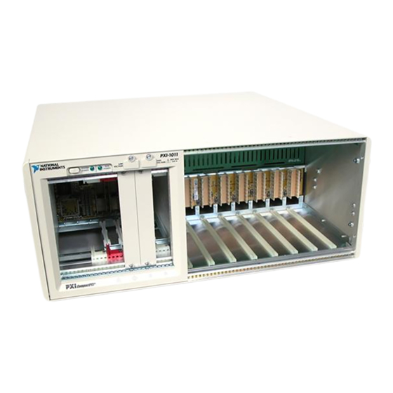
Page 18: Chassis Description
Chapter 1 Introduction Chassis Description Figure 1-1 shows the front view of the PXI-1011. Table 1-2 describes the front view items. ® ® ® s , , ? -41-t-.-- . - ---- - - - - 1 — = — . • m o - 7 - . - Page 19 Chapter 1 Introduction Table 1-2. PXI-1011 Chassis Front View Items (Continued) Item Description SCXI Low-Voltage Connect to the low-voltage analog bus (LVABO-3) on the SCXI Analog Bus Connectors subsystem backplane SCXI High-Voltage Connect to the high-voltage analog bus (HVABO-3) on the SCXI...
-
Page 20: Figure 1-2. Rear View Of The Pxi-1011 Chassis
P o w e r Entry Module 3 S C X I High-Voltage Analog Bus C o n n e c t o r Connector Figure 1-2. Rear View of the PXI-1011 Chassis Table 1-3. PXI-1011 Chassis Rear View Items Description Item Cool the chassis;... -
Page 21: Scxi Subsystem Overview
PXI-specific features. For example, you may want to use a standard CompactPCl network interface card in a PXI chassis. The signals on the PXI-1011 backplane P1 connector meet the requirements of the CompactPCl specification for both the peripheral and system modules. The PXI-specific signals are located on the P2 connector and are found only on the signals that are reserved or not used in the CompactPCl 64-bit specification. -
Page 22: System Controller Slot
This software uses the configuration information specific to each peripheral module to evaluate compatibility. This method is a flexible way to define local bus functionality that is not limited by keying hardware. PXI-1011 Chassis User Manual... -
Page 23: Scxi Control Slot
System Reference Clock The PXI-1011 supplies the PXI 10 MHz system clock signal (PXI_CLK10) independently to each peripheral slot. A n independent buffer (having a source impedance matched to the backplane and a skew of less than 1 ns between slots) drives the clock signal to each peripheral slot. - Page 24 400 Hz power applications—The PXI-1011 can operate on 400 Hz power systems but is not qualified for use in aircraft. A navigation hazard could exist if the PXI-1011 is operated in-flight with common avionics in use.
-
Page 25: Installation And Configuration
Place your PXI-1011 on a bench or in an instrument rack so that the fans (air inlets) and the air outlet apertures along both sides of the chassis have adequate ventilation. -
Page 26: Connecting Safety Ground
Refer to Figure 1-2, Rear View of the PXI-1011 Chassis, for a diagram locating the chassis grounding screw. To connect the safety ground, complete the following steps: 1. -
Page 27: Pxi Module Installation
Follow these steps to install a PXI module into a chassis slot: 1. F i r s t place the module edges into the PXI chassis module guides (top and bottom), as shown in Figure 1-1, Front View of the PXI-1011 Chassis. -
Page 28: Scxi Module Installation
Follow these steps to install SCXI modules: 1. T u r n off the SCXI subsystem using the switch shown in Figure 1-2, Rear View of the PXI-1011 Chassis. 2. Remove the front filler panel of an empty SCXI slot, if any. -
Page 29: System Configuration And Initialization Files
. i n i file. System controllers from National Instruments provide the pxisys . i n i file for the PXI-101 1 chassis so that the user should not need to use the chassis . i n i file. Refer to the documentation provided by the system controller for more information on pxisys . -
Page 30: Maintenance Procedures3
Maintenance This chapter describes basic maintenance procedures for the PXI-1011 chassis. Maintenance Procedures Service Interval Clean the chassis fan filters at a maximum interval of six months. Depending upon the amount of chassis use and ambient dust levels in the operating environment, the filters may require more frequent cleaning. -
Page 31: Interior Cleaning3
Refer to Figure I - I , Front View of the PXI-1011 Chassis, and Figure 1-2, Rear View of the PX1-101 1 Chassis, as you use the following procedures: I. -
Page 32: Troubleshooting The Pxi-101
4. T u r n on the system power switch and verify that the circuit breaker does not trip. 5. Ve r i f y that your PXI-1011 can meet the power requirements of your CompactPCl or PXI modules. Overloading the chassis can trip the breaker. -
Page 33: Appendix A Specifications
Table A-1. Maximum Currents Available to PXI Subsystem 'MAX Voltage (Steady-state current) +3.3 V 15.0 A +5 V 12.0 A +12 V 2.0 A " —12V 0,5A © National Instruments Corporation P X I - 1 0 1 1 Chassis User Manual... - Page 34 Module cooling systemF air circulation (positive pressurization) via two fans Slot airflow directionP I to P2, bottom of module to top of module Module cooling intakeB rear of chassis Module cooling exhaustT sides of chassis www.ni.com PXI-1011 Chassis User Manual...
- Page 35 I Random vibration profiles were developed in accordance with MIL-T-28800E CLASS 3 and MIL-STD-810E Method 514. Test levels exceed those recommended in M I L -STD-810E for Category 1 (Basic Transportation), Figures 514.4-1 through 514.4-3. © National Instruments Corporation P X I - 1 0 1 1 Chassis User Manual...
- Page 36 Backplane bare-board materialU 94 V-0 rated Backplane connectorsC to IEC 917 and IEC 1076-4-101, and are UL 94 V-0 rated Mechanical Overall dimensions4 by 43.9 by 17.7 cm (17.6 by 17.3 by 7 in.) Weight9 kg (20 Ib) PXI-1011 Chassis User Manual...
-
Page 37: Appendix B I/O Connectors
AD[0] ACK64# 3.3V AD[4] AD[3] AD[2] AD[7] 3.3V AD[6] AD[5] 3.3V AD[9] AD[8] M66EN C/BE[0]# AD[12] V(1/0) A D [ l l ] AD[10] GNI) 3.3V AD[15] AD[141 AD[13] SERR# 3.3V C/BE[1]# © National Instruments Corporation PXI-1011 Chassis User Manual... - Page 38 Appendi x 8 I / O Connectors Table B-1. P1 (J1) Connector Pin Assignments for the System Controller Slot (Continued) 3.3V S DONE SBO# PERR# DEVSEL# V(1/O) STOP# LOCK# 3.3V FRAME# IRDY# TR DY# 12-14 Key Area AD[18] AD[17] AD[16] C/BE[2]# AD[21] 3.3V...
- Page 39 AD[131 3.3V SERR# 3.3V C/BE[1111 SDONE SBO# PERR# 3.3V DEVSEL# V(1/0) STOP# LOCK# IRDY# TRDY# 3.3V FRAME# 12-14 Key Area AD1181 AD[171 AD[161 C/BE[21# AD[201 AD[19] AD1211 3.3V IDSEL AD1231 AD1221 C/BE131# © National Instruments Corporation PXI-1011 Chassis User Manual...
- Page 40 AD[381 AD[411 AD[40] AD[39] AD[421 AD[441 V(1/0) A131431 AD[45l GNI) A131471 AD1461 AD148] AD[491 V(I/0) AD[51] AD[50] AD152] AD[551 AD[54] AD1531 AD1561 AD[58] V(U0) AD1571 AD[591 AD[62] AD[61] AD1 601 AD[631 C/BE[4]# PAR64 V(1/0) C/BE[51# www.ni.corn PXI-1011 Chassis User Manual...
- Page 41 A D[201 A D[22] C/BEI31# IDSEL AD[231 AD[24I AD[26] V(I/0) A D[25I AD[291 AD[28] AD[27I ADI301 AD[31] REQ# 3.3V BRSVP1A5 BRSVP1B5 RST# GNT# BRSVP1 A4 V(1/O) INTP INTS INTA# INTB# INTC# INTD# © National Instruments Corporation PXI-1011 Chassis User Manual...
- Page 42 PAR64 C/BE[7]# C/BE[6]# V(I/0) PXI_BRSVB4 PXI_LBR7 PXI_LBR8 PXI LBR9 PXI_LBRIO PXI L B L 7 PXI_LBL8 PXI L B R I I PXI_LBRI2 SYSEN# PXI_LBL12 PXI_LBLI1 P X I L B L 9 GNI) PXI_LBLIO www.ni.com PXI-1011 Chassis User Manual...
-
Page 43: Technical Support Resources
Technical Support Resources This appendix describes the comprehensive resources available to you in the Technical Support section of the National Instruments Web site and provides technical support telephone numbers for you to use if you have trouble connecting to our Web site or if you do not have internet access. - Page 44 Web sites from www. ni . com/worldwide If you have trouble connecting to our Web site, please contact your local National Instruments office or the source from which you purchased your National Instruments product(s) to obtain support.
-
Page 45: Glossary
2. Software—a property of a function that begins an operation and returns before the operation is complete A m e r i c a n Wire Gauge © National Instruments Corporation P X I - 1 0 1 1 Chassis User Manual... - Page 46 A method of propagating signals along a bus in which the devices are daisy-chain prioritized on the basis of their position on the bus data acquisition—collecting and measuring electrical signals from sensors, transducers, and test probes or fixtures and inputting them to a computer for processing PXI-1011 Chassis User Manual...
- Page 47 IEC I n t e r n a t i o n a l Electrotechnical Commission; an organization that sets international electrical and electronics standards IEEE I n s t i t u t e of Electrical and Electronics Engineers © National Instruments Corporation P X I - 1 0 1 1 Chassis User Manual...
- Page 48 Instrumentation PXI_CLK1 0 pin that provides the PXI 10 MHz system clock signal to a peripheral slot PXI-1011 Chassis User Manual...
- Page 49 SCXI SCXI stands for Signal Conditioning eXtensions for Instrumentation and is a National Instruments product line designed to perform front-end signal conditioning for National Instruments plug-in DAQ devices. SCXI subsystem T h e...
- Page 50 -transistor logic U n d e r w r i t e r s Laboratories to peak voltage alternating current PXI-1011 Chassis User Manual...
-
Page 51: Index
AC main circuit breaker, resetting, 3-2 to 3-3 filter cleaning procedures, 3-2 PXI subsystem cooling specifications, A-2 to A-3 cables rear view of PXI-1011 (figure), 1-6 optional, 1-3 filler panel installation power cables (table), 1-2 PXI subsystem, 2-3 circuit breaker, resetting, 3-2 to 3-3... - Page 52 2-1 filler panel installation, 2-3 procedure, 2-2 interoperability with CompactPCI, 1-7 local bus, 1-8 National Instruments Web support, C-1 to C-2 peripheral slots, 1-8 SCXI control slot, 1-9 Star Trigger and local bus routing (figure), 1-9 online problem-solving and diagnostic...
- Page 53 1-1 to 1-2 resetting AC main circuit breaker, 3-2 to 3-3 technical support resources, C-1 to C-2 trigger bus, overview, 1-9 safety ground connection, 2-2 troubleshooting PXI-1011 power failure safety information, vi (table), 3-3 safety specifications, A-3 SCXI subsystem...
- Page 54 Index Web support from National Instruments, C-1 to C-2 online problem-solving and diagnostic resources, C-1 software-related resources, C-2 Worldwide technical support, C-2 PX1-101 1 Chassis User Manual...
- Page 55 Artisan Technology Group is your source for quality new and certified-used/pre-owned equipment • FAST SHIPPING AND SERVICE CENTER REPAIRS WE BUY USED EQUIPMENT DELIVERY Experienced engineers and technicians on staff Sell your excess, underutilized, and id at our full-service, in-house repair center We also offer credit for buy-backs and •...
Need help?
Do you have a question about the PXI-1011 and is the answer not in the manual?
Questions and answers