Table of Contents
Advertisement
Advertisement
Table of Contents

Subscribe to Our Youtube Channel
Related Manuals for National Instruments PXI-1045


Summary of Contents for National Instruments PXI-1045
- Page 1 NI PXI-1045 User Manual NI PXI-1045 User Manual August 2011 371565B-01...
- Page 2 11500 North Mopac Expressway Austin, Texas 78759-3504 USA Tel: 512 683 0100 For further support information, refer to the Technical Support and Professional Services appendix. To comment on National Instruments documentation, refer to the National Instruments Web site at and enter ni.com/info the Info Code feedback ©...
- Page 3 Warranty The NI PXI-1045 is warranted against defects in materials and workmanship for a period of one year from the date of shipment, as evidenced by receipts or other documentation. National Instruments will, at its option, repair or replace equipment that proves to be defective during the warranty period.
-
Page 4: Table Of Contents
Key Features ........................1-2 Chassis Description......................1-3 Optional Equipment .......................1-4 EMC Filler Panels ...................1-4 Rack Mount Kits....................1-4 Slot Blockers ....................1-4 PXI-1045 Backplane Overview ..................1-5 Interoperability with CompactPCI ..............1-5 System Controller Slot ..................1-5 Star Trigger Slot ....................1-6 Peripheral Slots....................1-6 Local Bus......................1-6 Trigger Bus......................1-8 System Reference Clock..................1-8... - Page 5 Replacing the Modular Power Supply................3-3 Removal ......................3-4 Installation....................... 3-4 Configuration ....................3-4 Connecting Safety Ground................3-5 Connecting to Power Source................3-5 Appendix A Specifications Appendix B Pinouts Appendix C Technical Support and Professional Services Glossary Index NI PXI-1045 User Manual ni.com...
-
Page 6: About This Manual
About This Manual The NI PXI-1045 User Manual contains information about installing, configuring, using, and maintaining the NI PXI-1045 18-slot chassis. Note This manual applies to chassis assemblies 189105E-01 and later. For earlier chassis revisions, refer to ni.com/support Conventions The following conventions appear in this manual: »... -
Page 7: Related Documentation
PXI Software Specification, Revision 2.2 • IEEE 1101.1-1991, IEEE Standard for Mechanical Core Specifications for Microcomputers Using IEC 603-2 Connectors • IEEE 1101.10, IEEE Standard for Additional Mechanical Specifications for Microcomputers Using IEEE 1101.1 Equipment Practice NI PXI-1045 User Manual viii ni.com... -
Page 8: Getting Started
Getting Started This chapter describes the key features of the PXI-1045 chassis and lists the kit contents and optional equipment you can order from National Instruments. Unpacking Carefully inspect the shipping container and the chassis for damage. Check for visible damage to the metal work. Check to make sure all handles, hardware, and switches are undamaged. -
Page 9: Key Features
The chassis’ modular design ensures a high level of maintainability, resulting in a very low mean time to repair (MTTR). The PXI-1045 complies with the PXI Hardware Specification, Revision 2.1, offering advanced timing and synchronization features. -
Page 10: Chassis Description
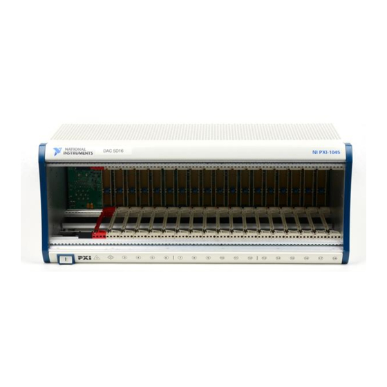
Tilt feet for bench-top applications • Rack mountable Chassis Description Figures 1-1 and 1-2 show the key features of the PXI-1045 chassis front and rear panels. Figure 1-1 shows the front view of the PXI-1045. Figure 1-2 shows the rear view. NI PXI-1045 1 Backplane Connectors (Located in slots 1–18) -
Page 11: Optional Equipment
EMC Filler Panels Optional EMC filler panel kits are available from National Instruments. Rack Mount Kits Two rack mount kit options are available for mounting the PXI-1045 chassis into a 19 in. instrument cabinet. Slot Blockers Optional slot blocker kits are available from National Instruments for improved thermal performance when all slots are not used. -
Page 12: Pxi-1045 Backplane Overview
32-bit/33 MHz PXI bridges. The PXI bus segment divisions are represented on the front of the chassis by vertical lines as shown in Figure 1-1. The PXI-1045 backplane is 32-bit PCI; 64-bit CompactPCI cards will operate in Note 32-bit mode in this chassis. -
Page 13: Star Trigger Slot
TTL side-band digital communication path that does not reduce the PXI bus bandwidth. Initialization software uses the configuration information specific to adjacent peripheral modules to evaluate local bus compatibility. NI PXI-1045 User Manual ni.com... - Page 14 Figure 1-3. PXI CLK_10 and Star Trigger Routing...
-
Page 15: Trigger Bus
System Reference Clock The PXI-1045 supplies the PXI 10 MHz system clock signal (PXI_CLK10) independently to each peripheral slot. An independent buffer (having a source impedance matched to the backplane and a skew of less than 250 ps between slots) drives the clock signal to each peripheral slot. -
Page 16: Installation And Configuration
Installation and Configuration This chapter describes how to install, configure, and use the PXI-1045 chassis. Before connecting the chassis to a power source, read this chapter and the Read Me First: Safety and Electromagnetic Compatibility document included with your chassis. -
Page 17: Chassis Cooling Considerations
Figure 2-1. Place the PXI-1045 on a bench top or in an instrument rack so that the fans (air inlets) and the air outlet apertures along both sides and the top of the chassis have adequate ventilation. -
Page 18: Setting Fan Speed
Install the chassis so that you can easily access the rear panel. This simplifies replacing the air filters or power supply shuttle, if necessary. Setting Fan Speed The fan-speed selector switch is on the rear panel of the PXI-1045. Refer to Figure 1-2, Rear View of the PXI-1045 Chassis, to locate the fan-speed selector switch. -
Page 19: Rack Mounting
Components, and the instructions supplied with the rack-mount kits to install your PXI-1045 in an instrument rack. Note You may want to remove the feet from the PXI-1045 when rack mounting. To do so, remove the screws holding the feet in place. Connecting Safety Ground... -
Page 20: Installing A Pxi Controller
Installing a PXI Controller This section contains general instructions for installing a PXI controller in the PXI-1045 chassis. Refer to your PXI controller user manual for specific instructions and cautions. Complete the following steps to install a controller. - Page 21 Figure 2-3 shows a PXI controller installed in the system controller slot of a PXI-1045 chassis. You can place CompactPCI or PXI modules in any other slot. NI PXI-1045 User Manual...
-
Page 22: Installing Pxi Modules
1 PXI-1045 Chassis 2 Injector/Ejector Rail 3 NI PXI Controller Figure 2-3. NI PXI Controller Installed in a PXI-1045 Chassis Installing PXI Modules Complete the following steps to install a module. Make sure the power switch is in the Off (Standby) position. -
Page 23: Power Switch Led Indicator
If the power switch LED is steady green (not flashing), the chassis is powered on and operating normally. Operating the PXI system outside of the specified temperature range may result Caution in loss of data, reduction of chassis life, or damage to equipment. NI PXI-1045 User Manual ni.com... -
Page 24: Remote Voltage Monitoring And Control
Remote Voltage Monitoring and Control The PXI-1045 chassis supports remote voltage monitoring and inhibiting through a male 9-pin D-sub connector located on the rear panel. Table 2-1 shows the pinout of the 9-pin D-sub connector. - Page 25 You can use a digital voltmeter to ensure all voltage levels in the PXI-1045 are within the allowable limits. Referring to Table 2-2, connect one lead of the voltmeter to a supply pin on the remote power monitoring connector (9-pin D-sub) on the rear panel.
-
Page 26: 10 Mhz Ref Rear Connectors
Installation and Configuration 10 MHz REF Rear Connectors There are two BNC connectors on the rear of the PXI-1045 chassis designated 10 MHz REF. The connectors are labeled IN and OUT. You can use them for supplying the backplane with a 10 MHz reference clock or routing the backplane’s PXI_CLK10 signal to another chassis. -
Page 27: Basic Pxi System Configuration
Identify each chassis by right-clicking on its entry, then selecting the appropriate chassis model through the Identify As submenu. Further expanding the PXI System branch will show all of the devices in the system that can be recognized by NI-VISA. Once your controller and NI PXI-1045 User Manual 2-12 ni.com... -
Page 28: Trigger Configuration In Max
PXI Trigger Bus Routing Some National Instruments chassis, such as the PXI-1006 and the PXI-1045, have the capability to route triggers from one bus to others within the same chassis using the Trigger Routing tab in MAX, as shown in Figure 2-5. This tab allows the routing of triggers from any single trigger bus to all of the other trigger buses in the chassis. -
Page 29: Using System Configuration And Initialization Files
.ini The capability documentation for the PXI-1045 chassis is contained in the file on the software media that comes with the chassis. The chassis.ini information in this file is combined with information about the system controller to create a single system initialization file called pxisys.ini... -
Page 30: Maintenance
This chapter describes basic maintenance procedures you can perform on the PXI-1045 chassis. Caution Disconnect the power cable prior to servicing the PXI-1045 chassis. Service Interval Clean the chassis fan filters at a maximum interval of six months. Depending on the amount of use and ambient dust levels in the operating environment, the filters may require more frequent cleaning. -
Page 31: Interior Cleaning
Cleaning and Replacing the Fan Filters Dirty fan filters can dramatically reduce the cooling performance of the PXI-1045 chassis. Clean the filters whenever they become visibly dirty. You can easily remove the chassis air filters from the rear of the chassis by removing the filter retainer. -
Page 32: Resetting The Ac Mains Circuit Breaker
Maintenance Resetting the AC Mains Circuit Breaker If the PXI-1045 is connected to an AC source and encounters an over-current condition, the circuit breaker on the rear panel will trip to prevent damage to the chassis. Complete the following steps to reset the circuit breaker. -
Page 33: Removal
Chapter 3 Maintenance Removal The PXI-1045 power-supply shuttle is a replacement part for the PXI-1045 chassis. Before attempting to replace the power-supply shuttle, verify that there is adequate clearance behind the chassis. Set the power switch on the front panel to the Off (nonrecessed) position. Disconnect the power cable and any other cables from the power-supply shuttle on the rear of the chassis. -
Page 34: Connecting Safety Ground
Connecting Safety Ground Refer to the Connecting Safety Ground section of Chapter 2, Installation Configuration. Connecting to Power Source Refer to the Connecting to Power Source section of Chapter 2, Installation Configuration. © National Instruments Corporation NI PXI-1045 User Manual... -
Page 35: Specifications
Specifications Caution If the PXI-1045 chassis is used in a manner inconsistent with the instructions or specifications listed by National Instruments, the protective features of the chassis may be impaired. This appendix contains specifications for the PXI-1045 chassis. Electrical AC Input Input voltage range......... - Page 36 59 A +12 V 8.5 A Peripheral slots +12 V 0.5 A System slot –12 V 4.5 A Load regulation Voltage Load Regulation +3.3 V <5% +12 V <5% +5 V <5% –12 V <5% NI PXI-1045 User Manual ni.com...
- Page 37 HIGH/AUTO speed selector Intake ..........Bottom rear of chassis Exhaust..........Along both sides and top of chassis To reset over-voltage protection, remove the mains for 30 seconds and then power back up. © National Instruments Corporation NI PXI-1045 User Manual...
- Page 38 Note For EMC compliance, operate this device with shielded cabling. CE Compliance This product meets the essential requirements of applicable European Directives as follows: • 2006/95/EC; Low-Voltage Directive (safety) • 2004/108/EC; Electromagnetic Compatibility Directive (EMC) NI PXI-1045 User Manual ni.com...
- Page 39 Environmental Operating temperature......0 to 55 °C Storage temperature ....... –40 to 71 °C Relative humidity Operating ........10 to 90% non condensing Nonoperational (storage) ....5 to 95% non conducting © National Instruments Corporation NI PXI-1045 User Manual...
- Page 40 Tested in accordance with IEC-60068-2-64. Nonoperating test profile developed in accordance with MIL-PRF-28800F and MIL-STD-810E Method 514. V(I/O) is connected to the +5 V DC power plane, so the same specs apply to V(I/O) and +5 V. NI PXI-1045 User Manual ni.com...
- Page 41 1 ps RMS in 10 Hz to 1 MHz range External clock output Connector........BNC on rear of chassis (ground-referenced) ±20% squarewave into 50 Output amplitude ......1 V into open circuit Output impedance ......50 ±5 © National Instruments Corporation NI PXI-1045 User Manual...
- Page 42 Weight ............12.6 kg (27.8 lbs) Chassis materials ........Sheet Aluminum (5052-H32, 3003-H14, and 6061-T6), Extruded Aluminum (6060-T6), Cold Rolled Steel, PC-ABS, Santoprene, Nylon Finish ............Conductive Clear Iridite on Aluminum Clear Chromate Zinc Plating on Cold Rolled Steel Polyurethane Enamel NI PXI-1045 User Manual ni.com...
- Page 43 Appendix A Specifications Figures A-1 and A-2 show the PXI-1045 dimensions. The holes shown are for the installation of the optional rack-mount kits as shown in Figure A-3. Notice that the front and rear rack mounting holes (size M4) are symmetrical.
- Page 44 Appendix A Specifications 2.52 1.01 12.700 (322.58) (64.0) (25.7) 15.50 (393.7) Figure A-2. PXI-1045 Dimensions (Bottom) in Inches (mm) NI PXI-1045 User Manual A-10 ni.com...
- Page 45 Appendix A Specifications Figure A-3 shows the PXI-1045 rack-mount kit components. 1 Front Rack Mount Kit 2 PXI-1045 Chassis 3 Optional Rear Rack-Mount Kit Figure A-3. PXI-1045 Rack Mount Kit Components © National Instruments Corporation A-11 NI PXI-1045 User Manual...
- Page 46 Pinouts This appendix describes the P1 and P2 connector pinouts for the PXI-1045 backplane. Table B-1 shows the P1 (J1) connector pinout for the System Controller slot. Table B-2 shows the P2 (J2) connector pinout for the System Controller slot.
- Page 47 AD[21] 3.3V AD[20] AD[19] C/BE[3]# AD[23] AD[22] AD[26] V(I/O) AD[25] AD[24] AD[30] AD[29] AD[28] AD[27] REQ0# 3.3V CLK0 AD[31] BRSVP1A5 BRSVP1B5 RST# GNT0# IPMB_PWR HEALTHY V(I/O) INTP INTS INTA# INTB# INTC# INTD# –12V TRST# +12V NI PXI-1045 User Manual ni.com...
- Page 48 BP(I/O) BP(I/O) BP(I/O) V(I/O) BP(I/O) BP(I/O) BP(I/O) BP(I/O) BP(I/O) BP(I/O) BP(I/O) 64EN# V(I/O) BP(I/O) BP(I/O) V(I/O) PXI_BRSVB4 BP(I/O) BP(I/O) CLK4 GNT3# REQ4# GNT4# CLK2 CLK3 SYSEN# GNT2# REQ3# CLK1 REQ1# GNT1# REQ2# © National Instruments Corporation NI PXI-1045 User Manual...
- Page 49 AD[21] 3.3V AD[20] AD[19] C/BE[3]# IDSEL AD[23] AD[22] AD[26] V(I/O) AD[25] AD[24] AD[30] AD[29] AD[28] AD[27] REQ# 3.3V AD[31] BRSVP1A5 BRSVP1B5 RST# GNT# IPMB_PWR HEALTHY V(I/O) INTP INTS INTA# INTB# INTC# INTD# –12V TRST# +12V NI PXI-1045 User Manual ni.com...
- Page 50 PXI_TRIG4 PXI_TRIG5 PXI_TRIG6 PXI_TRIG2 PXI_CLK10_IN PXI_CLK10 PXI_TRIG1 PXI_TRIG0 PXI_TRIG7 PXI_BRSVA15 PXI_STAR6 PXI_LBR6 V(I/O) V(I/O) V(I/O) V(I/O) 64EN# V(I/O) V(I/O) PXI_BRSVB4 PXI_LBR7 PXI_LBR8 PXI_LBR9 PXI_LBR10 PXI_LBR11 PXI_LBR12 PXI_STAR7 PXI_STAR8 PXI_STAR9 PXI_STAR10 PXI_STAR11 PXI_STAR12 © National Instruments Corporation NI PXI-1045 User Manual...
- Page 51 AD[21] 3.3V AD[20] AD[19] C/BE[3]# IDSEL AD[23] AD[22] AD[26] V(I/O) AD[25] AD[24] AD[30] AD[29] AD[28] AD[27] REQ# 3.3V AD[31] BRSVP1A5 BRSVP1B5 RST# GNT# IPMB_PWR HEALTHY V(I/O) INTP INTS INTA# INTB# INTC# INTD# –12V TRST# +12V NI PXI-1045 User Manual ni.com...
- Page 52 PXI_TRIG4 PXI_TRIG5 PXI_TRIG6 PXI_TRIG2 PXI_STAR PXI_CLK10 PXI_TRIG1 PXI_TRIG0 PXI_TRIG7 PXI_BRSVA15 PXI_LBL6 PXI_LBR6 V(I/O) V(I/O) V(I/O) V(I/O) 64EN# V(I/O) V(I/O) PXI_BRSVB4 PXI_LBR7 PXI_LBR8 PXI_LBR9 PXI_LBR10 PXI_LBR11 PXI_LBR12 PXI_LBL7 PXI_LBL8 PXI_LBL9 PXI_LBL10 PXI_LBL11 PXI_LBL12 © National Instruments Corporation NI PXI-1045 User Manual...
- Page 53 Technical Support and Professional Services Visit the following sections of the award-winning National Instruments Web site at for technical support and professional services: ni.com • Support—Technical support at includes the ni.com/support following resources: – Self-Help Technical Resources—For answers and solutions,...
- Page 54 Technical Support and Professional Services You also can visit the Worldwide Offices section of ni.com/niglobal to access the branch office Web sites, which provide up-to-date contact information, support phone numbers, email addresses, and current events. NI PXI-1045 User Manual ni.com...
- Page 55 Symbols ° Degrees. Equal or greater than. Equal or less than. Percent. Ohms. Amperes. Alternating current. ANSI American National Standards Institute. AUTO Automatic fan speed control. American Wire Gauge. © National Instruments Corporation NI PXI-1045 User Manual...
- Page 56 A method of propagating signals along a bus, in which the devices are prioritized on the basis of their position on the bus. DB-9 A 9-pin D-sub connector. Direct current. Declaration of Conformity. D-sub Subminiature D connector. NI PXI-1045 User Manual ni.com...
- Page 57 (1) grams; (2) a measure of acceleration approximately equal to 9.8 m/s GPIB General Purpose Interface Bus (IEEE 488). A measure of random vibration. The root mean square of acceleration levels in a random vibration test profile. Hours. Hertz; cycles per second. © National Instruments Corporation NI PXI-1045 User Manual...
- Page 58 90 to 132 VAC or 180 to 264 VAC). load regulation The maximum steady-state percentage that a DC voltage output will change as a result of a step change from no-load to full-load output current. NI PXI-1045 User Manual ni.com...
- Page 59 NEMA National Electrical Manufacturers Association. National Instruments. NI-DAQmx National Instruments driver which controls the operation of National Instruments data acquisition (DAQ) devices. NI-VISA National Instruments’ implementation of the VISA (Virtual Instrument System Architecture) I/O standard. NI-VISA provides support for the VISA API, and also provides VISAIC, a utility for instrument configuration and I/O function execution.
- Page 60 The 10 MHz REF IN and OUT BNC connectors on the rear of the chassis can be used to synchronize multiple chassis to one reference clock. The PXI backplane specification defines implementation guidelines for PXI_CLK10. NI PXI-1045 User Manual ni.com...
- Page 61 Glossary Transistor-transistor logic. Underwriter’s Laboratories. Volts. Volts alternating current, or V Peak-to-peak voltage. Watts. © National Instruments Corporation NI PXI-1045 User Manual...
- Page 62 See pinouts conventions used in the manual, vii cooling help, technical support, C-1 air cooling of PXI-1045, 2-2 air intake (figure), 2-3 filler panel installation, 2-3 setting fan speed, 2-3 installation, configuration, and operation slot blocker installation, 2-3...
- Page 63 PXI configuration in MAX, 2-11 services, C-1 PXI trigger bus routing, 2-13 NI support and services, C-1 trigger configuration, 2-13 PXI controller installed in a PXI-1045 chassis (figure), 2-7 rack mounting, 2-4 online product certification, A-5 remote voltage monitoring and inhibiting...
- Page 64 LED indicator, 2-8 pinout (table), 2-9 power up, testing, 2-4 power supply voltages (table), 2-10 programming examples (NI resources), C-1 PXI controller, 2-5 installing in a PXI-1045 chassis safety (figure), 2-7 specifications, A-4 PXI_CLK10, 1-8 safety and caution notices, 2-1...
- Page 65 A-4 troubleshooting (NI resources), C-1 Waste Electrical and Electronic Equipment (WEEE), A-5 star trigger (ST) slot unpacking the PXI-1045, 1-1 description, 1-6 P1 (J1) connector pinouts (table), B-4 P2 (J2) connector pinouts (table), B-5 support, technical, C-1 voltage monitoring connector. See D-sub...
Need help?
Do you have a question about the PXI-1045 and is the answer not in the manual?
Questions and answers