
Related Manuals for OM POWER OM4000 HF


Summary of Contents for OM POWER OM4000 HF
- Page 1 Instruction Manual OM4000 HF SHORTWAVE POWER AMPLIFIER WWW.OM-POWER.COM OM POWER, s.r.o. 93030 Báč 126, SLOVAKIA Contact : +421 905 321 410 e-mail : om-power@om-power.com...
-
Page 2: Table Of Contents
Cooling ……………………………………………………………………. 10 4.5. OPERATION ……………………………………………………………… 10 Operation Elements ……………………………………………………….. 11 5.1. Tuning of Power Amplifier …………………………………………….. 5.2. MAINTENANCE ………………………………………………………. Indication of Fault Conditions …………………………………………. 6.1. Fuse Replacement . .…………………………………………………..6.2. Tube Replacement …………………………………………………..6.3. Cleaning ……………………………………………………………..6.4. OM4000 HF POWER AMPLIFIER... - Page 3 APPENDIX ……………………………………………………………... Block Diagram of OM4000 HF Power Amplifier ……………...………... 7.1. OM4000 HF POWER AMPLIFIER...
-
Page 4: General Information
GENERAL INFORMATION 1.1. Introduction The OM Power model OM4000 HF is a manual tuning power amplifier, designed for use on all short wave amateur bands from 1.8 to 29.7 MHz (including WARC bands) and all modes. is equipped with a two pieces of ceramic tetrode FU728F. -
Page 5: Indicators
DO NOT ATTEMPT TO SHORT OR BYPASS safety switch under upper lid! WARNING! The OM4000 HF amplifier is neither to be used in a WET or HUMID environment nor to be exposed to RAINFALL! WARNING! Do not turn the amplifier on without having connected the ANTENNA or... -
Page 6: General Description
AT LEAST 5 minutes, allowing the electrolytic capacitors to discharge fully. Disconnect power cord from the outlet! WARNING! OM4000 HF amplifier can be operated ONLY if both of supply cables are connected! The amplifier reaches optimal parameters in 2 phase’s system, if you do not have 2 phases, connect both mains cords into the same phase. -
Page 7: Power Supply
Top view on the opened OM4000 HF FU728F PWR meter Blower Switch-on board Tetrode Output Pi-L Circuit Tuning capacitor Power supply board Subpanel 3.2. Power Supply Power supply of the amplifier is comprised of two of 3 kVA toroidal transformers. A soft start is provided using relays and resistors. -
Page 8: Safety Devices
The output of the transceiver is to be connected to the input of the amplifier via RG58 or similar cable. For the connection between the power amplifier and the antenna, RG213 or similar coaxial cable suited for high power is recommended. Both the INPUT and OUTPUT SO-239 sockets with Teflon insulation is used. OM4000 HF POWER AMPLIFIER... -
Page 9: Control Cable
During transmitting the middle pin is connected to the ground. The relays of the OM4000 HF have to be switched earlier than HF is applied (cold switching). Modern transceivers they have a time delay between PTT switching and power output. -
Page 10: Mains Supply
Mains Supply WARNING! The power Amplifier OM4000 HF has to be connected TO THE MAINS WITH BOTH CABLES! The amplifier reaches optimal parameters in the system with 2 phases. Every phase has to be able to deliver 3kVA. If you do not have 2 phases system, connect both mains cords into the same phase. -
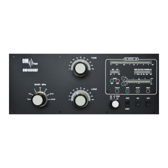
Page 11: Operation Elements
Capacity is low at „100“ and high at "0" on the scale. OFF - You switch off the amplifier by pressing this button. ON - You switch on the amplifier by pressing this button. After 3min of warm-up delay, the amplifier will be ready for operation. OM4000 HF POWER AMPLIFIER... -
Page 12: Tuning Of Power Amplifier
HV/IP/TUNE 5.2. Tuning of Power Amplifier The OM4000 HF amplifier is operated in class AB. Thus it’s possible to obtain a maximum output power at excellent linearity. For this purpose the amplifier has to be tuned carefully. WARNING! Before starting tuning you have to check if the right antenna or a 50 Ohms load resistance... - Page 13 Delivered tuning table was made for 50 Ohm loading of PA (dummy load). Each amplifier should have different values depending on used frequency and used type of antenna. Make your own table valid for your real conditions. OM4000 HF POWER AMPLIFIER...
- Page 14 Be sure to have not done any mistakes in choosing bands or TUNE/LOAD values! Be sure that VSWR is not higher than 2:1 and input power is LOW! After excluding possible human mistakes you will be able to work for long time with this amplifier! OM4000 HF POWER AMPLIFIER...
-
Page 15: Maintenance
Should a fault condition appear during the tuning or operation of the amplifier, the safety circuits of OM4000 HF will react. The amplifier will be turned to STBY mode. After abt. 2 sec the control circuits will switch the amplifier back to OPR. -
Page 16: Fuse Replacement
Manufacturer’s contacts: OM POWER, s.r.o. 93030 Báč 126, SLOVAKIA Phone : +421 905 321 410 e-mail : om-power@om-power.com 6.2. Fuse Replacemeent The user is allowed to change mains fuses (6,3 x 32mm), accesible from the rear panel, only. In the case of interrupted fuse (fuses) inside the power amplifier, contact your dealer, please. - Page 17 APPENDIX 7.1. Block Diagram of OM4000 HF Power Amplifier OM4000 HF POWER AMPLIFIER...
Need help?
Do you have a question about the OM4000 HF and is the answer not in the manual?
Questions and answers