
Related Manuals for OM POWER OM2500 HF


Summary of Contents for OM POWER OM2500 HF
- Page 1 Instruction Manual OM2500 HF SHORTWAVE POWER AMPLIFIER OM POWER, s. r. o. 930 30 Báč 126 SLOVAKIA E-mail: om-power@om-power.com...
-
Page 2: Table Of Contents
TABLE OF CONTENTS GENERAL INFORMATION Introduction ……………………………………………………………….. 1.1. Specification ……………………………………………………………..1.2. 1.2.1. Parameters …………………………………………………………………. 1.2.2. Protection Circuits ………………………………………………………… 1.2.3. Indicators ………………………………………………………………….. SAFETY INSTRUCTIONS ……………………………………………… GENERAL DESCRIPTION ………………………………………………. HF part ……………………………………………………………………. 3.1. Power Supply …………………………………………………………….. 3.2. Safety Devices ……………………………………………………………. 3.3. INSTALLATION ………………………………………………………… Grounding …………………………………………………………………... - Page 3 APPENDIX ……………………………………………………………... Band Blocking …………………………………………………………… 7.1. Block Diagram of OM2500 HF Power Amplifier (USA version) ………... 7.2.
-
Page 4: General Information
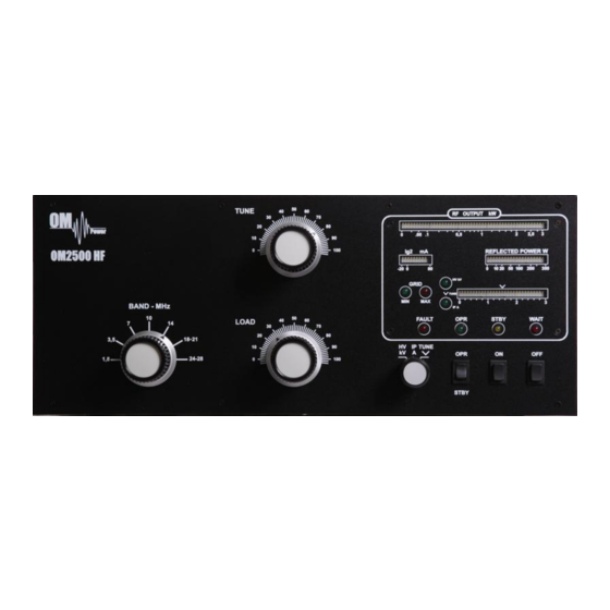
GENERAL INFORMATION 1.1. Introduction The OM Power model OM2500HF is a manual tuning, full legal limit amplifier, designed for heavy duty use on all short wave amateur bands from 1.8 to 29.7 MHz (including WARC bands) and all modes with no time limit. It is equipped with one GU84b ceramic tetrode. -
Page 5: Indicators
DO NOT ATTEMPT TO SHORT OR BYPASS safety switch under upper lid! WARNING! The OM2500 HF amplifier is neither to be used in a WET or HUMID environment nor to be exposed to RAINFALL! WARNING! Do not turn the amplifier on without having connected the ANTENNA or... -
Page 6: General Description
WARNING! Before opening the upper lid of the amplifier make sure that power supply has been disconnected AT LEAST 10 minutes allowing the electrolytic capacitors to discharge fully. Disconnect power cord from the outlet! CAUTION! The amplifier must be installed in such a way that free flow of hot air from the tube is allowed. -
Page 7: Power Supply
Top view on the opened OM2500 HF GU84B PWR meter Blower Switch-on board Tetrode Output Pi-L Circuit Tuning capacitor Power supply board Subpanel 3.2. Power Supply Power supply of the amplifier is comprised of two of 2,0 kVA toroidal transformers. A soft start is provided using relays and resistors. -
Page 8: Safety Devices
3.3. Safety Devices Control and monitoring circuits ensure control and safety during malfunctions of the PA. These are on the Control board, which is located on the chassis subpanel. INSTALLATION NOTE Read this chapter carefully prior you will start installation. Before unpacking inspect shipping woody container first, if it is not damaged. -
Page 9: Control Cable
During transmitting the middle pin is connected to the ground. The relays of the OM2500 HF have to be switched earlier than HF is applied (cold switching). Modern transceivers they have a time delay between PTT switching and power output. -
Page 10: Main Supply
Main Supply WARNING! Power Amplifiers OM2500 HF are manufactured for several different power systems. For US territory only one mains cable is used for two phases (2x120V) system. Cord is not removable from PA. Amplifier is equipped with two mains fuses (see rear panel). -
Page 11: Operation Elements
not visible condensation may develop, and this could result in damage to the high voltage circuits of the PA. CAUTION Never try to change antenna output during a transmission to avoid warranty loss. NOTE When you decide to have a short operating break, place the amplifier in the standby mode rather than switch it off. -
Page 12: Tuning Of Power Amplifier
HV/IP/TUNE 5.2. Tuning of Power Amplifier The OM2500 HF amplifier is operated in class AB. Thus it’s possible to obtain a maximum output power at excellent linearity. For this purpose the amplifier has to be tuned carefully. WARNING! Before starting tuning you have to check if the right antenna or a 50 Ohms load... - Page 13 The toroidal transformers are switched on step by step. The cooling blower for the final tube is switched on. The multi-meter bar graph measures the high voltage; the normal value is 2.8 kV The WAIT LED lights up CAUTION After switching on, please confirm that the blower is operating properly.
-
Page 14: Maintenance
Should a fault condition appear during the tuning or operation of the amplifier, the safety circuits of OM2500 HF will react. The amplifier will be turned to STBY mode. After approx. 2 sec the control circuits will switch the amplifier back to OPR. -
Page 15: Fuse Replacement
- zero output power during tuning HV + IP - tuning fault, incorrect tuning of the Pi-L output circuit In case your OM2500 HF amplifier is not working correctly, please contact the manufacturer or your dealer. Manufacturer’s contacts: OM POWER, s.r.o. -
Page 16: Tube Replacement
6.3. Tube Replacement In the case of vacuum tube damaging, contact the manufacturer or your dealer for ordering new one. You will get instructuions how to change tube and how to preset proper parameters, too. If you are not comfortable to replace vacuum tube itself, contact your Service Center, please. In the USA call or write to: Array Solutions 2611 North Belt Line Road... - Page 17 7.2. Block Diagram of OM2500 HF Power Amplifier (USA version)
Need help?
Do you have a question about the OM2500 HF and is the answer not in the manual?
Questions and answers