
Related Manuals for OM POWER OM4001F


Summary of Contents for OM POWER OM4001F
- Page 1 MADE IN SLOVAKIA OM4001HF SHORTWAVE POWER AMPLIFIER WWW.OM-POWER.COM OM Power, s.r.o. 93030 Báč 126, SLOVAKIA Contact : +421 905 321 410 e-mail : om-power@om-power.com e-mail : om-power@om- power.com...
-
Page 2: Table Of Contents
TABLE OF CONTENTS 1. GENERAL INFORMATION ..............4 1.1. Introduction ………………………………………………………. 1.2. Specification ………………………………………………………. 1.2.1. Parameters ………………………………………………. 1.2.2. Protection Circuits ………………………………………………. 1.2.3. Features ………………………………………………………. 2. SAFETY INSTRUCTIONS ………………………………………………. 3. GENERAL DESCRIPTION ………………………………………………. 3.1. HF Compartment …………………………………………………………. 3.2. Power Supply …………………………………………………………. 3.3. - Page 3 7. APPENDIX ………………………………………………………. 7.1. Primary AC selection ……………………………………………. 7.2. OM4001HF firmware upgrade …………………………..………… 7.3. Control panel connectors pin-out …………………………….…… 7.4. Block Diagram of the OM4001HF Power Amplifier …………..… 7.5. Troubleshooting ………………………………………………………. 7.6. Factory reset …………………………………………………………..
-
Page 4: General Information
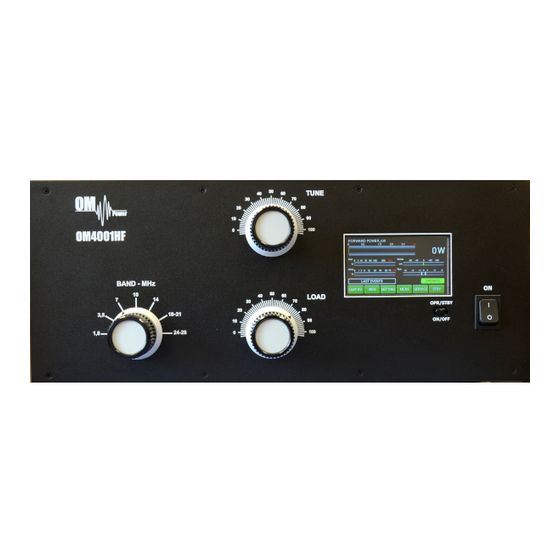
GENERAL INFORMATION 1.1. Introduction he OM Power model OM4001HF is designed for all short wave amateur bands from 1.8 to 29.7 MHz (including WARC bands) and all modes. It is equipped with a two ceramic tetrodes FU-728F. 1.2. Specification 1.2.1. Parameters Frequency Coverage Amateur Bands 1.8 –... -
Page 5: Protection Circuits
1.2.2. Protection Circuits There are several protection circuits used in the amplifier. They are activated when one or more parameters exceed defined values or some unwanted condition occurs. VSWR too high • Anode current too high • Anode voltage error •... -
Page 6: Safety Instructions
2. SAFETY INSTRUCTIONS DANGEROUS HIGH VOLTAGE INSIDE! The power amplifier is using high voltage up to 3300 V DC , which is very dangerous for human life! Read next safety instructions carefully first, before you will start to install and operate power amplifier! NEVER VIOLATE THE FOLLOWING SAFETY RULES! NEVER ALLOW CHILDREN to play around PA or to touch power amplifier or connected cables in working condition, or to push anything into the case holes! Never turn the amplifier on without the upper lid in place. -
Page 7: General Description
CAUTION The amplifier must be installed in such a way that free flow of hot air from the tube is allowed. The amplifier must not be installed in a constrained surrounding (i.e. tight shelves etc.). During extended operation the tube ventilation grid can reach high temperature. -
Page 8: Power Supply
Top view on the opened OM4001HF Tetrode FU728F Blower Switch-ON Board Output Pi-L Circuit Tuning Capacitor Front Subpanel Power Supply Board 3.2. Power Supply This Power amplifier uses two 3 KVA toroidal transformer. A soft start is provided using relays and resistors (placed on the switch-ON board). -
Page 9: Safety Devices
resistors are employed to protect the amplifier against overload (placed on the power supply board). The separate screen grid supply is regulated and stabilized with MOSFET circuits and delivers abt. 350V DC at 200mA. Control grid voltage is also stabilized (-120V DC). Change of stabilized first grid voltage is controlled by the software (EBS for example). -
Page 10: Grounding
4.1. Grounding The amplifier has to be grounded properly! Connect the screw on the rear panel of the amplifier to your local grounding system with a copper cable; use a cross- section of 4 mm at least. Connect your transceiver to the same grounding system of your shack carefully! Use minimum length cables and make certain that the connections are both physically and electrically sound. -
Page 11: Control Cable
4.3. Control Cable Control cable maintains TX / RX switching of the PA (TX GND). The cable is shielded. On the side of the power amplifier a CINCH-socket is used. On the side of your transceiver you have to use a socket suitable for this transceiver. During transmitting the middle pin is connected to the ground. -
Page 12: Operation
5. OPERATION Before switching PA on, make sure that amplifier is grounded, antenna or dummy load is connected, and line cord is plugged into the outlet. Be sure you have selected the proper AC input TAP (Sect 7.1) Do not turn PA on for at least 2 hours after unpacking and located in its operating location. -
Page 13: Om400Hf Control
ON/OFF Long press (1 sec.) for switching the PA ON (tube heating first), 2 seconds for PA OFF. Always use the ON/OFF button as this allows for a predetermined (software controlled) time to cool down the tube and inside the PA compartment. 5.2. -
Page 14: Preparing For Operation
5.3 Preparing for operation In STBY the amplifier is in bypass-mode and your transceiver is directly connected to the antenna. Maximum allowed power in bypass mode is 200 Watts! The bypass RF power is displayed if PA is in standby mode. To turn PA ON press ON/OFF button on the front panel (black one) and hold it abt. - Page 15 Press INFO button Type of supported TCVR and working A new button is visible – SET Umain. frequency are visible on the display. Press it. AUTO LED is ON. Type in the actual setting of the primary Type of supported TCVR and working voltage tap and press ENT.
- Page 16 Press SET for your callsign edit. The Type of supported TCVR and keyboard displays. working frequency are visible on the display. AUTO LED is ON. Type of supported TCVR and Type your callsign and press ENT. working frequency are visible on the display.
- Page 17 Electronic Bias Settings (EBS) is a significant feature of this power amplifier. It automatically allows lower plate current after pressing the PTT, regardless of whether operating CW or SSB mode, when no RF signal is present at the input. At the moment an RF signal is applied, the bias will automatically change to its working value.
- Page 18 By pressing the SERVICE button we are in the SERVICE settings mode. Type of supported TCVR and working Scroll to selected line and press SHOW frequency are visible on the display. or SET (depending on the line). AUTO LED is ON. We selected last 20 FAULTS to show.
- Page 19 Similar ways EBS2 can be preprogrammed (300mA by AUTO set). Or another value of EBS2 by MANUAL Set. Type of supported TCVR and working frequency are visible on the display. Scroll to CALIBRATION Ip, Is and press SET. Calibration will done automatically.
-
Page 20: Operation Mode
5.4.Operation mode Before switching to operation mode, check all connections between PA and TCVR. We are now back in the Main display. We are ready to go to the operation Type of supported TCVR and working mode. frequency are visible on the display. Press the black STBY/OPER button on the front panel or button OPERATE on touch screen display... - Page 21 When the antenna impedance has greater variance from 50 Ohms, it may be the case that the PA cannot deliver the full power 4000W, or some of the protection circuits may be automatically activated. In such cases we recommend doing a manual tuning. The best indication of proper PA tuning is the Screen Current.
-
Page 22: Maintenance
At the following picture you can see display of properly tuned amplifier Output power is 4078W, reflected power Type of supported TCVR and working about 3W and screen current is about +40 mA. frequency are visible on the display. AUTO LED is ON. If the amplifier demonstrates any malfunctions during tuning or it does not behave in accordance witch the TUNE procedure, interrupt the tuning procedure immediately and check the amplifier! Be sure there are not any mistakes in choosing antennas or bands! - Page 23 AUTO LED is ON. Never try to change or move any part inside the amplifier except the tube or fuses. Substitution of parts may void intrinsic safety! Manufacturer’s contacts: OM POWER, s.r.o. 930 30 Báč 126 SLOVAKIA Email: om-power@om-power.co...
-
Page 24: Fuse Replacement
6.2. Fuse Replacement The user is allowed to change mains fuses (6.3 x 32mm), accessible from the rear panel, only. In the case of fuse (fuses) interruption inside the power amplifier, exchange can be carried out only by professionally qualified persons! Internal fuses are located mainly on the SWITCH- on board (next to the HV transformer). -
Page 25: Appendix
7. APPENDIX 7.1. Primary AC voltage selection Primary section of the HV transformer is switchable for three values of AC voltage (220, 230, 240V) Factory settings is 230VAC. Before first starting the PA we recommend checking that the correct value is selected according to the AC voltage in your network. Side view on the opened OM4001HF HV supply board AC Selector... -
Page 26: Om4001Hf Firmware Upgrade
7.2. OM4001HF firmware upgrade Download the firmware upgrade software and latest firmware file for the OM4001HF from the official OM Power website http://www.om-power.com/downloads. Store it to OM4001HF folder created on your PC. NOTE: Use a serial null modem cable and connect the PC port on the OM4001HF rear panel with a COM port on the PC. - Page 27 Select the Firmware tab and click on the LOAD BIN button. Choose OM4001HF Vxxx.bin file in the OM4001HF folder. Type of supported TCVR and working frequency are visible on the display. AUTO LED is ON. Switch ON the power amplifier using the front panel green ON switch.
- Page 28 Press the SEND TO LINE button. Type of supported TCVR and working frequency are visible on the display. AUTO LED is ON. Press LOAD on the OM4001HF to start loading. Type of supported TCVR and working frequency are visible on the display.
-
Page 29: Control Panel Connectors Pin-Out
7.3. Control panel (rear side) connectors pin-out PC connector DB 9 female RS232 connection to the computer. For UPRADE firmware communication connect pin 2 TX-D, pin 3 RX-D and pin 5 GROUND KEY IN – RCA connector Input signal PTT switching voltage / current 5V /2mA) KEY OUT –... -
Page 30: Block Diagram Of The Om4001Hf Power Amplifier
7.4. Block Diagram of the OM4001HF Power Amplifier... -
Page 31: Troubleshooting
7.5. Troubleshooting The OM4001HF power amplifier contains several protection circuits, which constantly monitor operation of the Amplifier. When the firmware defined parameters exceed defined operating levels, a WARNING appears in the LAST EVENTS window of the PA front panel. If some parameters exceed a defined critical level, a FAULT is activated and the PA will automatically switch to STBY mode. - Page 32 High voltage supply fault. Check the fuses on HV Plate voltage error Check plate power supply board. Low voltage on the grid. Check fuse F9 on HV supply Grid voltage is low Check grid power supply board. Check fuse F10 on HV supply board and fuse F1 on Screen voltage error Check screen power supply the Screen...
-
Page 33: Factory Reset
7.6. Factory reset: In the case of very abnormal behavior of the OM4001HF it is possible to do a factory reset. This will reset all the amplifier parameters back to the factory default values. Press and hold the ON/OFF button and press the green Main power switch for several seconds until the following display appears.
Need help?
Do you have a question about the OM4001F and is the answer not in the manual?
Questions and answers