
Related Manuals for OM POWER OM4000A


Summary of Contents for OM POWER OM4000A
- Page 1 Instruction Manual OM4000A SHORTWAVE POWER AMPLIFIER WWW.OM-POWER.COM OM POWER, s.r.o. 93030 Báč 126, SLOVAKIA Contact : +421 905 321 410 e-mail : om-power@om-power.com...
-
Page 2: Table Of Contents
TABLE OF CONTENTS GENERAL INFORMATION 1.1. Introduction 1.2. Specification 1.3. Parameters 1.4. Protection Circuits 1.5. Indicators SAFETY INSTRUCTIONS GENERAL DESCRIPTION 3.1. HF Part 3.2. Power Supply 3.3. Safety Devices INSTALLATION 4.1. Grounding 4.2. Coaxial Cable 4.3. I/O Box and Interface 4.4. - Page 3 Example of connection USB Micro KEYER II with another ICOM 7.7. Example of connection USB Micro KEYER II with YAESU or ELECRAFT 7.8. Example of connection PA with MicroHAM MKII, (MK2R+ etc.) CI-V output 7.9. Block Diagram of the OM4000A power Amplifier...
-
Page 4: General Information
1.1. Introduction he OM Power model OM4000A is a fully automatic power amplifier, designed for use on all short wave amateur bands from 1.8 to 29.7 MHz (including WARC bands) and all modes. It is equipped with a two pieces of ceramic tetrode FU728F. -
Page 5: Protection Circuits
1.2.2. Protection Circuits There are 11 special protection circuits used in the amplifier. They are activated when one or more of next parameters exceed defined values or some unwanted occasion occurs. VSWR too high Input power too high ... -
Page 6: Safety Instructions
2 phase’s system, if you do not have 2 phases, connect both mains cords into the same phase. WARNING! The OM4000A amplifier is neither to be used in a WET or HUMID environment nor to be exposed to RAINFALL! WARNING! -
Page 7: General Description
FU728F in a grounded-cathode circuit (input into control grids). OM4000A amplifier achieves excellent linearity by the voltage stabilization of the control grid bias and the screen voltage. The power input is given to the control grids, using a broadband input circuit with an input impedance of 50 Ohms. -
Page 8: Power Supply
The output of the amplifier is a Pi-L circuit. The ceramic capacitor for TUNE and LOAD are divided. This enables the amplifier to be tuned exactly and makes it possible to easily return to the previously set positions after band changes. Top view on the opened OM4000A Tetrode FU728F PWR Meter... -
Page 9: Safety Devices
3.3. Safety Devices Control and monitoring circuits ensure control and safety during malfunctions of the PA. These are on the Control board, which is located on the chassis subpanel. INSTALLATION NOTE Read this chapter carefully prior you will start installation. Before unpacking inspect shipping woody container first, if it is not damaged. -
Page 10: I/O Box And Interface
During transmitting the middle pin is connected to the ground. The relays of the OM4000A have to be switched earlier than HF is applied (cold switching). Modern transceivers they have a time delay between PTT switching and power output. - Page 11 KEY IN RCA Phono - Input signal PTT switching voltage / current 5V /2 mA) KEY OUT RCA Phono - Output signal PTT (maximum switching of 30V / 50mA) CI-V Mono 3.5mm Jack for connection of ICOM TCVRs or devices that provide compatible CI-V protocol.
- Page 12 CONTROL The CONTROL socket is a single DB-15 connector that provides many connections to the amplifier from your transceiver. Use shielded cable for all connections to this connector. You will need to fabricate a cable with the proper connector for your transceiver or use individual connectors as described below.
-
Page 13: Mains Supply
4.4. Mains Supply WARNING! The power Amplifier OM4000A has to be connected TO THE MAINS WITH BOTH CABLES! The amplifier reaches optimal parameters in the system with 2 phases. Every phase has to be able to deliver 3 kVA. If you do not have 2 phases system, connect both mains cords into the same phase. -
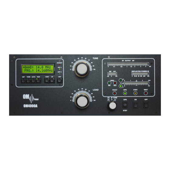
Page 14: Operation Elements
CAUTION Before switching PA on, check all connections between PA and TCVR. CAUTION Do not turn PA on for at least 2 hours after unpacking it and locating in its operating location. Especially when amplifier is moved from a cold place to a warm one because not visible condensation may develop, and this could result in damage to the high voltage circuits of the CAUTION Never try to change antenna output during a transmission to avoid warranty loss. - Page 15 TUNE Anode capacitor for tuning, tuning of higher frequencies to "0", lower frequencies to “100”. LOAD Output capacitor tunes antenna load resistance to amplifier. Capacity is low at „100“ and high at "0" on the scale. You switch off the amplifier by pressing this button. You switch on the amplifier by pressing this button.
-
Page 16: Configuration Of Power Amplifier
INHIBIT Indicates interruption of transmission during the tuning process of the PA. If indicated by RED LED then PA is in STBY mode. If during a retune operations within the same BAND, then the PA will retune according to the frequency of the transceiver. When changing the BAND – INHIBIT will stay lit until the KEY IN is released and the tuning process will start. -
Page 17: Tcvr Support Settings
Example of Automatic mode with ICOM TCVR. Type of supported TCVR and working frequency is visible on the display. AUTO LED is ON 5.2.1. TCVR Support Settings Supported transceivers : ICOM, ELECRAFT, KENWOOD, TEN-TEC, ORION, YAESU. Press SET button and scroll UP/DWN to CHOOSE TCVR Confirm CHOOSE TCVR by pressing SET again and scroll UP / DWN to your... -
Page 18: Connection With Not Supported Tcvrs
5.2.2. Connection with not supported TCVRs For communication with TCVRs, that are not supported by OM4000A (for example JST-245 and older types of Kenwood), an external IF-232 converter is to be used. You can also use devices from several companies that produce compatible CI-V output which deliver frequency information in ICOM format through the CI-V output. -
Page 19: Communication Loss
5.2.3. Communication loss If TCVR is not connected or communication settings are incorrect, the message “COMMUNICATION LOST” will be displayed. You can still use PA by entering MANUAL mode (MAN Button) or by correcting the transceiver connection problem. Example of Communication loss message. 5.2.4. -
Page 20: Bandpass Filter Settings
Then select how many antennas you want per current band (1 or 2) and always confirm your selection by pressing SET. By scrolling UP / DWN you assign which PORT is used on your external antennas switch for this particular antenna. (ANT 1 ON PORT 01). -
Page 21: Mute Option
ALC connection. The ALC Input of your transceiver should be connected to the “ALC Out” of OM4000A. It is important to notice, that this is not a true ALC, only the transmitter will be blocked in this way during the process of PA tuning. -
Page 22: Lcd Settings Menu
UP / DWN buttons. 5.3. Tuning of Power Amplifier he OM4000A amplifier is operated in class AB. Thus it’s possible to obtain a maximum output power at excellent linearity. For this purpose the amplifier has to be tuned carefully. - Page 23 100mA is exceeded, the safety devices will switch the amplifier to STBY mode. 5.3.1. AUTO or MANUAL There are two possibilities of operation mode in OM4000A – AUTO or MANUAL. Normally, when you are using CAT interface connection between TCVR and PA, in AUTO mode PA will tune automatically to the TCVR frequency.
- Page 24 The amplifier is prepared for operation with the following automatic steps: Toroidal transformers are switched on step by step. The cooling blower for the final tube is switched on. The multi-meter bar graph measures the high voltage; the normal value is 3.3 KV ...
- Page 25 5.3.3. Tuning Adjustment Entering the TUNE mode is done by pressing the TUNE button. The OM4000A then switches the transceiver to RTTY and sets the frequency to corresponding segment. By changing the values of TUNE and LOAD capacitors we tune the PA as per manual tuning instructions (see 5.3.2.). The...
-
Page 26: Maintenance
Should a fault condition appear during the tuning or operation of the amplifier, the safety circuits of OM4000A will react. The amplifier will be turned to STBY mode. After approx. 2 sec the control circuits will switch the amplifier back to OPR. -
Page 27: Fuse Replacement
In case your OM4000A amplifier is not working correctly, please contact the manufacturer or your dealer. Manufacturer’s contacts: OM POWER, s.r.o. 93030 Báč 126, SLOVAKIA Phone : +421 905 321 410 e-mail : om-power@om-power.com 6.2. Fuse Replacemeent The user is allowed to change mains fuses (6,3 x 32mm), accesible from the rear panel, only. In the case of interrupted fuse (fuses) inside the power amplifier, contact your dealer, please. -
Page 28: Example Of Connection With Icom
7.1. -
Page 29: Example Of Connection With Elecraft
7.2. Example of connection for ELECRAFT... -
Page 30: Example Of Connection With Yeasu
7.3. Example of connection with Yeasu... -
Page 31: Example Of Connection With Antenna Switch And Bpf
7.4. Example of connection with antenna switch and BPF... -
Page 32: With Ic7800 Or Ic7700
7.5. Example of connection USB micro KEYER II with IC7800 or IC7700... -
Page 33: With Another Icom
7.6. Example of connection USB micro KEYER II with another Icom... -
Page 34: With Yaesu Or Elecraft
7.7. Example for connection USB micro KEYER II with Yeasu or ELECRAFT... -
Page 35: Example Of Connection Pa With Microham Mkii, (Mk2R+ Etc.)
7.8. Example of connection PA with MicroHAM MKII, (MK2R+ etc ) with CI-V output... -
Page 36: Block Diagram Of The Om4000A Power Amplifier
7.9. Block Diagram of the OM4000A Power Amplifier...
Need help?
Do you have a question about the OM4000A and is the answer not in the manual?
Questions and answers