Table of Contents
Advertisement
Available languages
Available languages
Air-Conditioners
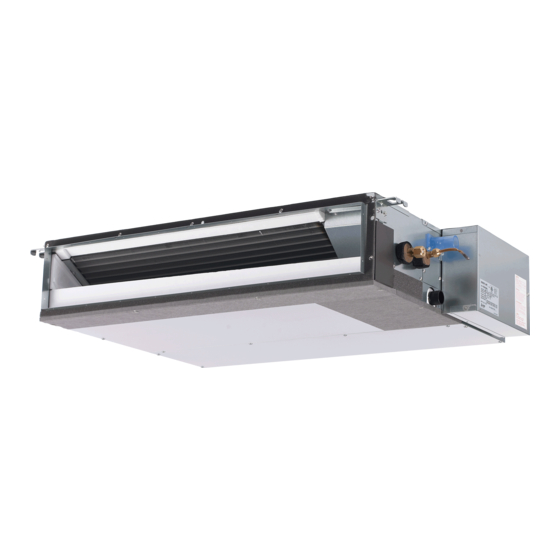
SEZ-KD09,KD12,KD15,KD18NA
INSTALLATION MANUAL
For safe and correct use, please read this installation manual thoroughly before installing the air-conditioner
unit.
MANUEL D'INSTALLATION
Veuillez lire le manuel d'installation en entier avant d'installer ce climatiseur pour éviter tout accident et vous
assurer d'une utilisation correcte.
FOR INSTALLER
POUR L'INSTALLATEUR
English
Français
Advertisement
Table of Contents

Related Manuals for Mitsubishi Electric SEZ-KD09


Summary of Contents for Mitsubishi Electric SEZ-KD09
-
Page 1: Installation Manual
Air-Conditioners SEZ-KD09,KD12,KD15,KD18NA INSTALLATION MANUAL FOR INSTALLER English For safe and correct use, please read this installation manual thoroughly before installing the air-conditioner unit. MANUEL D’INSTALLATION POUR L’INSTALLATEUR Français Veuillez lire le manuel d’installation en entier avant d’installer ce climatiseur pour éviter tout accident et vous... - Page 2 4 300 mm [11-13/16 in] or more E Ceiling surface F Service space (viewed from the side) G Service space (viewed from the direction of arrow) (Unit: mm [in]) Model SEZ-KD09 700 [27-9/16] 752 [29-5/8] 798 [31-7/16] 660 [26] 800 [31-1/2]...
- Page 3 [Fig. 6-1] (Unit: mm [in]) øB øA Model 6.35 [1/4] SEZ-KD09, 12 9.52 [3/8] SEZ-KD15 12.7 [1/2] 6.35 [1/4] SEZ-KD18 12.7 [1/2] 6.35 [1/4] a Indoor unit b Outdoor unit [Fig. 6-3] [Fig. 6-4] [Fig. 6-5] 90° a Burr c Spare reamer...
- Page 4 [Fig. 6-10] Max. 20m [65 ft] 1.5-2 m [5 to 7 ft] Max. 300 mm [11-13/16 in] Correct piping Wrong piping A Insulation (9 mm [3/8 in] or more) B Downward slope (1/100 or more) C Support metal K Air bleeder L Raised M Odor trap Grouped piping...
- Page 5 [Fig. 7-1] A Air inlet B Air outlet C Access door D Ceiling E Canvas duct F Air filter G Inlet grille [Fig. 8-1] A Indoor unit B Outdoor unit C Wired remote controller D Main switch/fuse E Ground wire For Power supply For Power supply...
- Page 6 [Fig. 8-3] A Indoor terminal block A Indoor terminal block 1.5 mm [AWG 16]) longer than other cables B Ground wire (green/yellow) B Ground wire (green/yellow) 5 Remote controller cable Wire No ¥ size (mm ) : Cable 2C ¥ 0.3 C Indoor/outdoor unit connecting cable 3- core 1.5 mm [AWG 16] or more...
- Page 7 [Fig. 9-1] [Fig. 9-2] TEST RUN COOL, HEAT ˚F ˚F ˚C SIMPLE ˚F SIMPLE TEMP. ON/OFF TEMP. ON/OFF MENU ON/OFF FILTER MENU ON/OFF FILTER BACK MONITOR/SET CHECK TEST BACK MONITOR/SET CHECK TEST PAR-21MAA CLOCK OPERATION CLEAR PAR-21MAA CLOCK OPERATION CLEAR A ON/OFF button F Error code display A CHECK button...
-
Page 8: Table Of Contents
Contents 1. Safety precautions ................... 8 9. Test run ....................14 2. Selecting the installation location ............. 8 10. Maintenance ..................15 3. Selecting an installation site & accessories ..........9 4. Fixing hanging bolts ................. 9 5. Installing the unit ..................9 This Installation Manual only applies to the indoor unit and the SUZ series out- 6. -
Page 9: Selecting An Installation Site & Accessories
Center of gravity and Product Weight Model name W (mm [in]) L (mm [in]) X (mm [in]) Y (mm [in]) Z (mm [in]) Product Weight (kg [Ib]) SEZ-KD09 625 [24-5/8] 752 [29-5/8] 263 [10-3/8] 351 [13-27/32] 106 [4-3/16] 19 [42] SEZ-KD12... -
Page 10: Refrigerant Piping Work
6. Refrigerant piping work 6.1. Refrigerant pipe 6.2.3. Putting nut on [Fig. 6-5] (P.3) [Fig. 6-1] (P.3) a Flare nut a Indoor unit b Copper tube b Outdoor unit • Remove flare nuts attached to indoor and outdoor unit, then attach them on pipe/ Refer to the outdoor unit Instruction Manual for restrictions on tube after burr removal. - Page 11 6. Refrigerant piping work Refrigerant pipe insulation • After connecting refrigerant piping, insulate the joints (flared joints) with thermal *Close insulation tubing as shown below. Stop valve [Fig. 6-9] (P.3) *Open A Pipe cover (120 mm [3/4 in] small diameter) (accessory) B Caution: Pull out the thermal insulation on the refrigerant piping at the site, insert the flare nut to flare Hexagonal wrench...
-
Page 12: Duct Work
Work procedure Electrical specification Input capacity Main Switch/Fuse (A) 1. Remove two screws to detach the electric component cover. Power supply SEZ-KD09 SEZ-KD12 SEZ-KD15 SEZ-KD18 2. Route each cable through the wiring intake into the electric component box. (Pro- (1 phase ~/N, 208/230V, 60Hz) cure power cable and in-out connecting cable locally and use remote control cable supplied with the unit.) -
Page 13: Caution
8. Electrical work [Fig. 8-2-1] (P.5) B-1. To lead the remote controller cord from the back of the controller: A Screw holding cover (2pcs) B-2. To run the remote controller cord through the upper portion: B Cover (3) For direct installation on the wall [Fig. -
Page 14: Test Run
8. Electrical work Function table 1 Select unit number 00 Mode Settings Mode no. Setting no. Initial setting Check Power failure automatic recovery*1 Not available (AUTO RESTART FUNCTION) Available *1 Indoor temperature detecting Indoor unit operating average Set by indoor unit’s remote controller Remote controller’s internal sensor LOSSNAY connectivity Not Supported... -
Page 15: Maintenance
9. Test run 9.3. Self-check [Fig. 9-2] (P.7) A CHECK button 9.3.1. Wired remote controller B Refrigerant address 1 Turn on the power. C TEMP. button 2 Press the [CHECK] button twice. D IC: Indoor unit 3 Set refrigerant address with [TEMP] button if system control is used. OC: Outdoor unit 4 Press the [ON/OFF] button to stop the self-check. - Page 16 Index 1. Consignes de sécurité ................16 9. Marche d’essai ..................23 2. Choisir l’emplacement de l’installation ........... 16 10. Entretien ....................24 3. Sélection de l’emplacement d’installation et accessoires ...... 17 4. Fixation des boulons de suspension ............17 Le manuel d’installation ne concerne que l’unité...
- Page 17 Centre de gravité et poids du produit Nom du modèle W (mm [in]) L (mm [in]) X (mm [in]) Y (mm [in]) Z (mm [in]) Poids du produit (kg [Ib]) SEZ-KD09 625 [24-5/8] 752 [29-5/8] 263 [10-3/8] 351 [13-27/32] 106 [4-3/16] 19 [42] SEZ-KD12...
- Page 18 5. Installation de l’appareil 5.1. Suspension de l’appareil 5.2. Assurer l’emplacement de l’appareil et monter les s s s s s Transporter l’appareil intérieure jusqu’au site en la conservant dans son boulons de suspension emballage d’origine. s s s s s Utiliser le calibre livré avec le panneau pour vérifier si l’appareil et les bou- s s s s s Pour le suspendre, utiliser une poulie de levage pour le soulever et le faire lons de suspension sont placés à...
- Page 19 6. Mise en place des tuyaux de réfrigérant 6.3. Connexion des tuyaux La laisser ainsi pendant une ou deux minutes. Vous assurer que l’aiguille de la [Fig. 6-8] (P.3) soupape multiple de manomètre reste sur la même position. Vérifier que le mano- •...
- Page 20 6. Mise en place des tuyaux de réfrigérant Tuyaux groupés [Fig. 6-12] (P.4) * Evacuation par gravite D D. E. ø 32 mm [1-1/4 in] TUBE PVC A Appareil intérieur E Elargir le plus possible. 10 cm [3-15/16 in] environ.- B Couvre-tube (30 mm [3/16 in]) (accessoire) F Appareil intérieur C Sangle (accessoire)
- Page 21 8.1. Alimentation électrique [AWG 16] ou plus D Bornier extérieur Spécification électrique Capacité de disjoncteur (A) E Cordon d’alimentation électrique SEZ-KD09 SEZ-KD12 SEZ-KD15 SEZ-KD18 Alimentation électrique 1 Câble de connection pour appareil intérieur/extérieur 3 conducteurs, 1,5 mm [AWG 16] ou (1 phase ~/N, 208/230V, 60Hz) plus, conforme à...
- Page 22 8. Installations électriques 8 Appuyer sur la touche MODE E, les numéros de programmation et de mode (1) 8.4. Réglage des fonctions (Sélection des fonctions par et (2) changeront et seront continuellement affichés, et les détails de la program- la télécommande) mation pourront être confirmés.
- Page 23 9. Marche d’essai 9.1. Avant la marche d’essai 9.2. Marche d’essai s Lorsque l’installation, le tuyautage et le câblage des appareils intérieur et 9.2.1. Utilisation de la télécommande filaire extérieur sont terminés, vérifier l’absence de fuites de réfrigérant, la fixation 1 Mettre l’appareil sous tension au moins 12 heures avant l’essai de fonctionne- des câbles d’alimentation et de commande, l’absence d’erreur de polarité...
- Page 24 9. Marche d’essai 9.3. Auto-vérification [Fig. 9-2] (P.7) A Touche CHECK (vérification) 9.3.1. Pour la télécommande filaire B Adresse du réfrigérant 1 Mettre sous tension. C Touche TEMP. 2 Appuyer deux fois sur la touche [CHECK] (vérification). D IC: Appareil intérieur 3 Régler l’adresse du réfrigérant à...
- Page 25 This product is designed and intended for use in the residential, commercial and light-industrial environment. Please be sure to put the contact address/telephone number on this manual before handing it to the customer. HEAD OFFICE: TOKYO BLDG., 2-7-3, MARUNOUCHI, CHIYODA-KU, TOKYO 100-8310, JAPAN KB79K740H02...