Mitsubishi Electric SEZ-KD09NA Technical & Service Manual
Indoor unit
Hide thumbs
Also See for SEZ-KD09NA:
- Technical & service manual (44 pages) ,
- Installation manual (25 pages) ,
- Specifications (3 pages)
Table of Contents
Advertisement
SPLIT-TYPE, HEAT PUMP AIR CONDITIONERS
TECHNICAL & SERVICE MANUAL
Indoor unit
[Model names]
SEZ-KD09NA
SEZ-KD12NA
SEZ-KD15NA
SEZ-KD18NA
INDOOR UNIT
TEMP.
WIRED REMOTE
CONTROLLER
[Service Ref.]
SEZ-KD09NA.TH
SEZ-KD12NA.TH
SEZ-KD15NA.TH
SEZ-KD18NA.TH
Model name
indication
ON/OFF
November 2008
REVISED EDITION-B
CONTENTS
1. PART NAMES AND FUNCTIONS ········2
2. SPECIFICATIONS·································4
3. OUTLINES AND DIMENSIONS··········14
4. WIRING DIAGRAM ·····························15
5. REFRIGERANT SYSTEM DIAGRAM·······16
6. HEATER CONTROL ···························17
7. TROUBLESHOOTING·························20
8. DISASSEMBLY PROCEDURE ···········30
CM
No.HWE08020
Advertisement
Table of Contents
Troubleshooting

Related Manuals for Mitsubishi Electric SEZ-KD09NA


Summary of Contents for Mitsubishi Electric SEZ-KD09NA
-
Page 1: Table Of Contents
SPLIT-TYPE, HEAT PUMP AIR CONDITIONERS November 2008 No.HWE08020 REVISED EDITION-B TECHNICAL & SERVICE MANUAL Indoor unit [Model names] [Service Ref.] SEZ-KD09NA.TH SEZ-KD09NA SEZ-KD12NA.TH SEZ-KD12NA SEZ-KD15NA.TH SEZ-KD15NA SEZ-KD18NA.TH SEZ-KD18NA CONTENTS 1. PART NAMES AND FUNCTIONS ········2 2. SPECIFICATIONS·································4 3. OUTLINES AND DIMENSIONS··········14 4. -
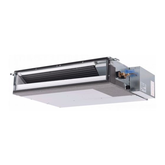
Page 2: Part Names And Functions
PART NAMES AND FUNCTIONS Indoor Unit SEZ-KD09NA.TH SEZ-KD12NA.TH SEZ-KD15NA.TH SEZ-KD18NA.TH Air outlet Air outlet duct flange Air inlet Wired remote controller Once the controls are set, the same operation mode can be repeated by simply pressing the ON/OFF button. ●... - Page 3 ● Display “Sensor” indication Displayed when the remote controller sensor is used. Day-of-Week For purposes of this explanation, Shows the current day of the week. all parts of the display are shown as lit. During actual operation, only Time/Timer Display the relevant items will be lit.
-
Page 4: Specifications
SPECIFICATIONS SEZ-KD09NA SEZ-KD12NA Model Name Capacity Cooling Heating Cooling Heating BTU/h 9000 10900 12000 13600 Power source 208/230V (60Hz) 208/230V (60Hz) Power input 0.06 0.04 0.07 0.05 Current 0.51 0.39 0.57 0.46 Temperature set range Remote controller ˚ F( ˚ C) - Page 5 SEZ-KD15NA SEZ-KD18NA Model Name Capacity Cooling Heating Cooling Heating BTU/h 15000 18000 17200 20100 Power source 208/230V (60Hz) 208/230V (60Hz) Power input 0.09 0.07 0.09 0.07 Current 0.74 0.63 0.74 0.63 Temperature set range Remote controller ˚ F( ˚ C) 67 to 86 (19 to 30) 63 to 83 (17 to 28) 67 to 86 (19 to 30)
- Page 6 SOUND CRITERION CURVES <60Hz> <60Hz> SEZ-KD09NA.TH SEZ-KD09NA.TH NOTCH SPL(dB) LINE NOTCH SPL(dB) LINE External static pressure: High External static pressure: High Middle Middle 0.02[in.WG](5Pa) 0.06[in.WG](15Pa) NC-70 NC-70 NC-60 NC-60 NC-50 NC-50 NC-40 NC-40 NC-30 NC-30 APPROXIMATE APPROXIMATE TERESHOLD OF TERESHOLD OF...
- Page 7 <60Hz> <60Hz> SEZ-KD12NA.TH SEZ-KD12NA.TH NOTCH SPL(dB) LINE NOTCH SPL(dB) LINE High High External static pressure: External static pressure: Middle Middle 0.02[in.WG](5Pa) 0.06[in.WG](15Pa) NC-70 NC-70 NC-60 NC-60 NC-50 NC-50 NC-40 NC-40 NC-30 NC-30 APPROXIMATE APPROXIMATE TERESHOLD OF TERESHOLD OF HEARING FOR HEARING FOR NC-20 NC-20...
- Page 8 <60Hz> <60Hz> SEZ-KD15NA.TH SEZ-KD15NA.TH NOTCH SPL(dB) LINE NOTCH SPL(dB) LINE High High External static pressure: External static pressure: Middle Middle 0.02[in.WG](5Pa) 0.06[in.WG](15Pa) NC-70 NC-70 NC-60 NC-60 NC-50 NC-50 NC-40 NC-40 NC-30 NC-30 APPROXIMATE APPROXIMATE TERESHOLD OF TERESHOLD OF HEARING FOR HEARING FOR NC-20 NC-20...
- Page 9 <60Hz> <60Hz> SEZ-KD18NA.TH SEZ-KD18NA.TH NOTCH SPL(dB) LINE NOTCH SPL(dB) LINE High High External static pressure: External static pressure: Middle Middle 0.02[in.WG](5Pa) 0.06[in.WG](15Pa) NC-70 NC-70 NC-60 NC-60 NC-50 NC-50 NC-40 NC-40 NC-30 NC-30 APPROXIMATE APPROXIMATE TERESHOLD OF TERESHOLD OF HEARING FOR HEARING FOR NC-20 NC-20...
- Page 10 INDOOR FAN PERFORMANCE AND CORRECTED AIR FLOW SEZ-KD09NA SEZ-KD09NA (External static pressure 0.02[in.WG](5Pa)) 208/230V 60Hz (External static pressure 0.06[in.WG](15Pa)) 208/230V 60Hz [0.16] [0.20] Limit Limit [0.16] [0.12] High [0.12] [0.08] [0.08] Middle High Rated point [0.04] Middle [0.04] Rated point...
- Page 11 SEZ-KD12NA SEZ-KD12NA (External static pressure 0.02[in.WG](5Pa)) 208/230V 60Hz (External static pressure 0.06[in.WG](15Pa)) 208/230V 60Hz [0.16] [0.20] [0.16] [0.12] Limit [0.12] Limit [0.08] High [0.08] High Middle Rated point [0.04] Middle [0.04] Rated point [212] [247] [282] [318] [353] [388] [424] [212] [247] [282]...
- Page 12 SEZ-KD15NA SEZ-KD15NA (External static pressure 0.02[in.WG](5Pa)) 208/230V 60Hz (External static pressure 0.06[in.WG](15Pa)) 208/230V 60Hz [0.16] [0.20] Limit Limit [0.16] [0.12] High [0.12] [0.08] High Middle [0.08] Middle Rated point [0.04] [0.04] Rated point [282] [318] [353] [388] [424] [459] [494] [530] [565] [282]...
- Page 13 SEZ-KD18NA SEZ-KD18NA (External static pressure 0.02[in.WG](5Pa)) 208/230V 60Hz (External static pressure 0.06[in.WG](15Pa)) 208/230V 60Hz [0.16] [0.20] Limit Limit [0.16] [0.12] High [0.12] Middle [0.08] High [0.08] Middle Rated point [0.04] [0.04] Rated point [318] [353] [388] [424] [459] [494] [530] [565] [600] [636] [671] [318] [353] [388]...
-
Page 14: Outlines And Dimensions
OUTLINES AND DIMENSIONS SEZ-KD09NA.TH Unit : mm(in.) SEZ-KD12NA.TH SEZ-KD15NA.TH SEZ-KD18NA.TH Drain pipe(O.D.ø32(1-1/4)) 345(13-19/32) (Emergency draining) 37(1-15/32) 100(3-15/16) Suspension bolt hole 20(13/16) 157.5 (6-7/32) 4-14X30(9/16X1-3/16) Slot 12(1/2) 37(1-15/32) 15(19/32) 2XE-ø2.9(1/8) L-ø2.9(1/8) outlet inlet Air filter 10(13/32) 625(Suspension bolt pitch) (1-15/16) (24-5/8) Knockout hole ø27(1-3/32) -
Page 15: Wiring Diagram
WIRING DIAGRAM SEZ-KD09NA.TH SEZ-KD12NA.TH SEZ-KD15NA.TH SEZ-KD18NA.TH INSIDE SECTION OF CONTROL BOX TB15 TO MA REMOTE CONTROLLER I. B. CN01 (Black) CN24 CN32 CN3C (Blue) (Yellow) CN51 CN41 ZNR02 CN2L CN22 (Blue) ON OFF FUSE DC310~340V ZNR01 Rectify circuit LED2 LED3... -
Page 16: Refrigerant System Diagram
REFRIGERANT SYSTEM DIAGRAM SEZ-KD09NA.TH SEZ-KD12NA.TH SEZ-KD15NA.TH SEZ-KD18NA.TH Strainer Heat exchanger Refrigerant GAS pipe connection (Flare) Condenser/evaporator temperature thermistor (TH5) Refrigerant flow in cooling Refrigerant flow in heating Refrigerant LIQUID pipe connection (Flare) Pipe temperature thermistor/liquid Room temperature (TH2) thermistor (TH1) -
Page 17: Heater Control
HEATER CONTROL 6-1. Control specifications and Function setting Table 1 shows how the field-installed heater is controlled. Select the desired pattern in the table below, and set the Function on the indoor units as shown in Table 1. Table.1 [Function table] Select unit numbers 01 to 03 or all units (AL[wired remote controller] / 07[wireless remote controller]) Mode Setting... - Page 18 6-3. PAC-YU25HT (Optional Parts) installation The following section describes installation of the External Heater Adapter that connects to SEZ-KD NA series indoor unit. This products is the special wiring parts to drive an electric heater with the air conditioner. (1) Parts list Check that the following parts are included in the package.
- Page 19 For relay X use the specifications given below Operation coil Rated voltage: 12VDC Power consumption: 0.9W or less * Use the diode that is recommended by the relay manufacturer at both ends of the relay coil. The length of the electrical wiring for the PAC-YU25HT is 2 meters (6-1/2 ft.) To extend this length, use sheathed 2-core cable.
-
Page 20: Troubleshooting
TROUBLESHOOTING 7-1. CAUTIONS ON TROUBLESHOOTING (1) Before troubleshooting, check the followings: 1 Check the power supply voltage. 2 Check the indoor/outdoor connecting wire for mis-wiring. (2) Take care the followings during servicing. 1 Before servicing the air conditioner, be sure to turn off the remote controller first to stop the main unit, and then turn off the breaker. - Page 21 • If the unit cannot be operated properly after the test run has been performed, refer to the following table to remove the cause. Symptom Cause Wired remote controller LED 1, 2 (PCB in outdoor unit) •For about 2 minutes after power-on,op- For about 2 After LED 1, 2 are lighted, LED 2 is PLEASE WAIT...
-
Page 22: Self-Diagnosis Action Table
Note: Refer to the manual of outdoor unit for the details of display 7-3. SELF-DIAGNOSIS ACTION TABLE such as F, U, and other E. Abnormal point and detection method Countermeasure Error Code Cause 1 Defective thermistor 1–3 Check resistance value of thermistor. Room temperature thermistor (TH1) characteristics... - Page 23 Abnormal point and detection method Countermeasure Error Code Cause Freezing/overheating protection is (Cooling or drying mode) (Cooling or drying mode) 1 Clogged filter (reduced airflow) 1 Check clogging of the filter. working 1 Freezing protection (Cooling mode) 2 Short cycle of air path 2 Remove shields.
-
Page 24: Noise
Abnormal point and detection method Countermeasure Error Code Cause 1 Defective thermistor 1–3 Check resistance value of thermistor. Abnormality of pipe temperature ther- mistor / Condenser-Evaporator (TH5) characteristics For characteristics, refer to (P1) above. 1 The unit is in three-minute resume pro- 2 Check contact failure of connector (CN44) 2 Contact failure of connector on the indoor controller board. -
Page 25: Noise
Abnormal point and detection method Countermeasure Error Code Cause ∗ Check LED display on the outdoor control cir- 1 Contact failure, short circuit or, Indoor/outdoor unit communication error (Signal receiving error) cuit board. (Connect A-control service tool, mis-wiring (converse wiring) of 1 Abnormal if indoor controller board PAC-SK52ST.) indoor/outdoor unit connecting... -
Page 26: Troubleshooting By Inferior Phenomena
7-4. TROUBLESHOOTING BY INFERIOR PHENOMENA Note: Refer to the manual of outdoor unit for the detail of remote controller. Phenomena Cause Countermeasure (1)LED2 on indoor controller board • When LED1 on indoor controller board is also off. 1 Power supply of rated voltage is not supplied to out- 1 Check the voltage of outdoor power is off. - Page 27 7-5. TEST POINT DIAGRAM 7-5-1. Indoor controller board SEZ-KD09NA.TH SEZ-KD12NA.TH SEZ-KD15NA.TH CN01 Power supply voltage (208 - 230VAC) SEZ-KD18NA.TH Emergency operation Fuse(6.3A 250V) Model selection Capacity setting CN32 Remote start/stop adapter CN01 CN24 Heater control (12VDC) CN22 For MA remote controller cable con- nection (10 - 13 VDC (Between 1 and 3.))
- Page 28 7-6. TROUBLE CRITERION OF MAIN PARTS SEZ-KD09NA.TH SEZ-KD12NA.TH SEZ-KD15NA.TH SEZ-KD18NA.TH Part name Check method and criterion Room temperature Measure the resistance with a tester. thermistor (Part temperature 10°C(50°F) ~ 30°C(86°F)) (TH1) Normal Abnormal Pipe temperature 8kΩ~20kΩ Opened or short-circuited thermistor/liquid...
- Page 29 7-7. DC FAN MOTOR (FAN MOTOR/ INDOOR CONTROLLER BOARD) Check method of DC fan motor (fan motor / indoor controller circuit board) Notes · High voltage is applied to the connecter (CNMF) for the fan motor. Give attention to the service. ·...
-
Page 30: Disassembly Procedure
DISASSEMBLY PROCEDURE Exercise caution when removing heavy parts. SEZ-KD09NA.TH SEZ-KD12NA.TH SEZ-KD15NA.TH SEZ-KD18NA.TH 1. Control box 1. Removing the control box cover (1) Remove the two fixing screws on the cover (A) to remove it. Fig. 1 Fig. 2 2. Thermistor (Intake air) 1. - Page 31 Exercise caution when removing heavy parts. 3. Drainpan 1. Removing the filter and the bottom plate (1) Push up the tab on the filter, and pull out the filter in the direction of the arrow 1. (2) Remove the fixing screws on the bottom plate (D), (E) to remove it.
- Page 32 Exercise caution when removing heavy parts. 4. Thermistor (Condenser / evaporator) (Liquid pipe) 1. Remove the drain pan according to the proce- dure in section [3]. 2. Removing the Heat exchanger cover (1) Remove the four fixing screws on the heat exchanger cover (F) to remove it.
- Page 33 Exercise caution when removing heavy parts. 5. Fan and fan motor 1. Removing the filter and the bottom plate (1) Push down the tab on the filter, and pull out the filter in the direction of the arrow 1. (2) Remove the fixing screws on the bottom plate (J) to remove it.
- Page 34 Exercise caution when removing heavy parts. 6. Bearing [KD15·18NA model only] 1. Removing the bearing (1) Remove the two fixing screws on the bearing cover (K) to remove it. Fig. 13 (2) Remove the two bearing retainer screws to remove the bearing. Fig.
- Page 35 New publication, effective Nov. 2008. HWE08020 Specifications subject to change without notice. Printed in Japan...