Table of Contents
Advertisement
Quick Links
Advertisement
Table of Contents

Related Manuals for Sanyo VDC-D1184VA


Summary of Contents for Sanyo VDC-D1184VA
-
Page 1: Instruction Manual
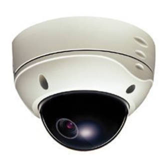
INSTRUCTION MANUAL VDC-D1184VA VDC-D2184VA COLOR CCD CAMERA VDC-D1184VA (SURFACE TYPE) VDC-D2184VA (IN-CEILING TYPE) About this manual Before installing and using the camera, please read this manual carefully. Be sure to keep it handy for later reference. -
Page 2: Table Of Contents
Depending on the conditions of use, installation and environment, FEATURES please be sure to make the appropriate settings and adjustments. If you need help with installation and/or settings, please consult your dealer. • The optical filter is switched automatically to color image or black and white image according to the subject brightness. -
Page 3: Information To User
(2) this device must accept any interference received, including interference that may cause undesired operation. Changes or modifications not expressly approved by Sanyo may This installation should be made by a qualified service person and void the user’s authority to operate this camera. -
Page 4: Precautions
Disconnect the power greasy smoke or steam or where the dampness may get too high. supply immediately, and consult your dealer (or a Sanyo Authorized Protect from high temperatures Service Center). -
Page 5: Installation
(Model VDC-D2184VA) settings and adjustments are necessary. 73mm Installing the Model VDC-D1184VA Use the supplied hexagonal wrench to remove the four fixing screws (B) of dome cover (A). Make screw holes and a cable hole in the cushioning sheet (D) that attaches to the back of the camera unit (C). - Page 6 INSTALLATION Connections Pass the power cable/day-night cable (E) and video cable (F) from the camera unit through the cable hole in the ceiling. DC 12 V connection AC 24 V connection (Power cable/day-night cable) DC12 AC24 Cable – Power cable –...
-
Page 7: Settings
SETTINGS The illustration shows the factory default settings for the switches in the camera setup section. When changing the settings and adjustments for this camera, loosen the camera unit screw (A) and remove the lens unit in the direction of the arrow. - Page 8 SETTINGS C • • • • B/W (color/black and white) switch setting High speed electronic shutter setting This switch lets you select the timing of the automatic switching of Normally, the speed setting switches for the high speed electronic the optical filter to color image or black and white image, according shutter are all set to the down (OFF) position.
- Page 9 SETTINGS Backlight compensation setting (BL-M mode: 64 sections) This camera has two different backlight compensation functions: Normally backlight compensation switch 5 (BL-M) and 6 (BL-C) are set to the down (OFF) position. Change the backlight compensation switch settings depending on the conditions. •...
-
Page 10: White Balance Adjustment
SETTINGS White balance adjustment Line phase adjustment Normally the switch 7 (WB) is set to the down (ATW: auto white When using a camera switcher to connect 2 cameras or more to one balance) position and the white balance is adjusted automatically. If a monitor, there may be a vertical roll of the images when switched. - Page 11 SETTINGS Manual color/black and white setting Lens iris adjustment Connect each cable as indicated below, to set the image to black and You will need to set the LEVEL (VR121) volume when shooting in the white or color as desired. conditions described below.
-
Page 12: Adjustment
Loosen the pan adjustment screw, adjust the panning position of the lens and then re-tighten the screw. Model: VDC-D1184VA Remove the lens unit A from the pan chassis, loosen the pan adjustment screw B, turn the chassis to adjust the panning position to a position where one of the three screw holes C is visible, and then re-tighten the screw. -
Page 13: Troubleshooting
If it still does not perform When setting up the camera, connect a monitor to this video output correctly, please consult your dealer or a Sanyo Authorized Service pin and to the GND screw using alligator clip cables, then using the Center. -
Page 14: Specifications
Power consumption : 2.9 W Picture elements : 811 (H) x 508 (V) Weight : VDC-D1184VA: Approx. 1,350 g Effective picture elements : 768 (H) x 494 (V) VDC-D2184VA: Approx. 1,015 g Synchronizing system : Internal sync, Line lock Dimensions (mm) - Page 15 OBLIGATIONS In order to obtain warranty service, the product must be delivered to and picked up from an Authorized Sanyo Service Center at the user’s expense, unless specifically stated otherwise in this warranty. The names and addresses of Authorized Sanyo Service Centers may be obtained by calling the toll-free number listed below.
- Page 16 Printed on recycled paper SANYO Electric Co., Ltd. 1AC6P1P2650-- L5AK4/US, L5AL4/US (0403KP-CZ) Printed in Japan...