Table of Contents
Advertisement
Advertisement
Table of Contents

Related Manuals for Craftsman 351.217130


Summary of Contents for Craftsman 351.217130
- Page 1 Operator's Manual RI:IFTSMI:IN ° THICKNESS PLANER Model No. 351.217130 CAUTION: Read and follow all Safety Rules and Operating Instructions before First Use of this Product. Sears, Roebuck and Co., Hoffman Estates, IL 60179 U.S.A. 16318.00 Draft (02/05/00)
- Page 2 PREPARE WORK AREA FOR JOB • Keep work area clean. Cluttered work areas invite accidents. Warranty ........• Do not use power tools in dangerous environments. Safety Rules ......• Do not use power tools in damp or wet locations. Do Unpacking .........
- Page 3 • Use recommended accessories (refer to page ??). Use Of improper accessories may cause risk of injury to persons. WARNING: Do not attempt assembly if parts are • Handle workpiece correctly. Protect hands from pos- missing. Use this manual to order replacement parts. sible injury.
- Page 4 UNWRAP LINE CORD • Base of planer has four mounting holes (A). Holes Refer to Figure 4. form a rectangle 12" x 20". Use a square to mark )osition on work surface, • The line cord (A) is securely wrapped around cord wraps (B), on the rear of the planer.
- Page 5 accept the tool plug. • Do not remove or alter grounding prong in any manner. In the event of a malfunction or breakdown, grounding • If the extension cord is worn, cut or damaged in any providesa path of least resistance for electrical shock. way, replace it immediately.
- Page 6 SWITCH LOCK +--, -,( ..Refer to Figure 11. The planer can be locked from unauthorized use by locking the switch. To lock the switch: • Turn the switch to OFF position and disconnect plan- er from power source. • Pull the key (A) out.
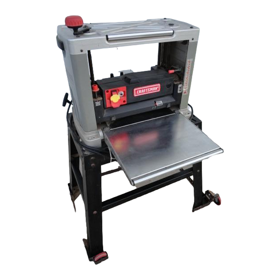
- Page 7 Do not back the work toward the infeed table. DESCRIPTION Take precautions against kickback. Do not permit any- Craftsman 13" planer finishes rough-cut lumber to size one to stand or cross in line of cutterhead's rotation. and planes soft and hardwoods up to 6" thick and 13"...
- Page 8 DEPTH OF CUT AVOID DAMAGE TO BLADES Thickness, planing refers to the sizing of lumber to a • Thickness planer is a precision woodworking desired thickness while creating a level surface parallel machine and should be used on quality lumber only. to the opposite side of the board.
- Page 9 • Position the workpiece with the face to be planed on top. • Turn the planer ON. Planer will operate best if kept in good condition and • Rest board end on in-feed roller plate and direct properly adjusted. board into planer. CHECK FOR WORN BLADES •...
- Page 10 • Remove gibusing two magnets (D) provided. BRUSH INSPECTION AND REPLACEMENT WARNING: Turn planer off and disconnect from power source. Brush life depends on amount of load on motor. Regularly inspect brushes after 100 hours of use. Brushes are located on either side of planer motor. ,Figure 20 - Remove GIb NOTE: Magnets can be easily disengaged from gib by tilting them to left or right.
- Page 11 LUBRICATION • Set the planer back on it's base. • Motor and cutterheed bearings are sealed and need • Make a test cut to verify adjustment. no lubrication. REPLACING V-BELT • Gears and elevation screws should be cleaned of Refer to Figures 23, 24 and 25. debris and greased.
- Page 12 ;YMPTOM i POSSIBLE CAUSE(S) i CORRECTIVE ACTION 1. Replace blades per instructions. Snipe i l.Dull blades See "Maintenance." (gouging at ends of board) 12. Inadequate support of long boards t 2.Support long boards. See "Avoiding Snipe? 3.Uneven force on cutterhead 13.Gently push board when board is in contact with only one feed roller.
- Page 13 NOTES...
- Page 14 Model 351.21 7130 Figure 23 - Replacement Farts lllustmtlon for Motor _"...
- Page 15 PART NO. DESCRIPTION QTY..........16081.00 4-1.59 x 12ram Threaded Forming Screw 16082.00 Switch Cover 04287.00 Circuit Breaker I 01090,00 5-0.8 x 15mm Pan Head Screw _ 16083.00 Line Cord ....16084.00 4-0.7 x 8mm Washer Head Screw 16085.00 Wire Clip 16086.00 Housing, Left...
- Page 16 Model 351.217130 Flgure 24 - Replacement Parts lllustmtlon for Base...
- Page 17 ; KEY I NO. PART NO. DESCRIPTION QTY. ; ._N_O_L___PART - NO., DESCRIPTION QTY. ! 116095.00 ', Cover 00221.00 3AMI-10 Retaining Ring 109631.00 ! Plug ' 22 ; 03812.00 6-1.0 x 10mm Pan Head Screw ! 4 !16096.00 i 8-1.25 x 16mm Socket Pan i 16105.00 Guide Plate Head Screw...
- Page 18 Model 351.217130 Figure 25 - Replacement Parts Illustration for Rollercase...
- Page 19 PART NO. DESCRIPTION QTY. PART NO. DESCRIPTION QTY. 16ii4.00' Wrenoh 16145.00 i 5 x 5 x 9mm Key 00519.00 i 3AM1-12 Retaining Ring 16115.00 Magnet Tool 03853.00 Chain Sprocket 116116.00 I Tool Tray 16084,00 4-.07 x 8mm Washer Head Screw 00533,00 3AM1-15 Retaining Ring i 49...
- Page 20 In U.S.A. or Canada for in-home major brand repair service: Call 24 hours a day, 7 days a week 1-800-4-MY-HOME °_(1-800-469-4663) Para pedir servicio de reparacibn a domicilio - 1-800-676-5811 Au Canada pour tout le service - 1-877-LE-FOYER sM (1-877-533-6937) For the repair or replacement parts you need: Call 6 a.m.