Advertisement
Available languages
Available languages
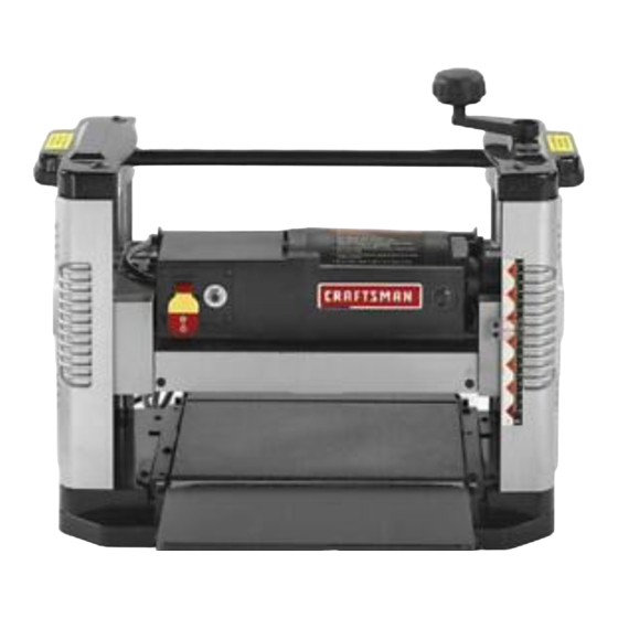
Operator's Manual
CRRFTSMRN
121/2 , ,
THICKNESS
PLANER
Model No.
351.217581
CAUTION:
Read and follow
all Safety Rules and Operating
Instructions
before First Use
of this Product. Keep this
manual with tool.
Sears Brands Management
Corporation,
Hoffman
Estates, IL 60179 U.S.A.
www.sears.com/craftsman
30674.01 Draft (11/04/09)
Advertisement
Table of Contents

Related Manuals for Craftsman 351.217581


Summary of Contents for Craftsman 351.217581
- Page 1 121/2 , , THICKNESS PLANER Model No. 351.217581 CAUTION: Read and follow all Safety Rules and Operating Instructions before First Use of this Product. Keep this manual with tool. Sears Brands Management Corporation, Hoffman Estates, IL 60179 U.S.A. www.sears.com/craftsman 30674.01 Draft (11/04/09)
- Page 2 ONE-YEAR FULL WARRANTY ON CRAFTSMAN TOOL • Do not use power tools in dangerous environments. if this Craftsman tool fails due to a defect in material or • Do not use power tools in damp or wet locations. Do workmanship within one year from the date of purchase, call 1-800-4-MY-HOME®...
-
Page 3: Install Handle
• Avoid accidental start-up. Make sure that the switch is in the OFF position before plugging in. • Do not force tool. It will work most efficiently at the rate for which it was designed. • Keep hands away from moving parts and cutting surfaces. -
Page 4: Grounding Instructions
ATTACH DUST CHUTE within range may cause overheating and motor burn- out. Heavy loads require that voltage at motor terminals Refer to Figure 15, page 14. be no less than the voltage specified. Planer is best used along with a dust collector. Dust Power supply to the motor is controlled by a switch chute is included. -
Page 5: Specifications
Canada.) Where a 3-prong to 2-prong grounding adapter is Craftsman 121/2 ' ' planer finishes rough-cut lumber to permitted, the rigid green tab or terminal on the side size and planes soft and hardwoods up to 6" thick and of the adapter must be securely connected to a 121/2 ' ' wide. -
Page 6: Operating Controls
Keep hands clear of all moving parts. Do not force cut. Slowing or stalling will overheat motor. Allow automatic feed to function properly. Use quality lumber. Blades last longer and cuts are smoother with good quality wood. Do not plane material shorter than 15", narrower than 3/,,>wider than 12112"... - Page 7 FEEDING WORK • Quality of thickness planing depends on the opera- tot's judgement about the depth of cut. The planer is supplied with planing blades mounted in the • Depth of cut depends on the width, hardness, damp- cutterhead and infeed and outfeed rollers adjusted to the ness, grain direction and grain structure of the wood.
-
Page 8: Changing Blades
• Snipe is more apparent when deeper cuts are taken • Feed work in direction of grain Work fed against grain will have chipped, splintered edges Planer will operate best if kept in good condition and properly adjusted CHECK FOR WORN BLADES •... -
Page 9: Brush Inspection
BRUSH INSPECTION AND REPLACEMENT • Release and remove vise plier. • Set the planer back on its base. WARNING: Turn planer off and disconnect from power source. Brush life depends on amount of load on motor. • Make a test cut to verify adjustment. Regularly inspect brushes after 100 hours of use. - Page 10 SYMPTOM CORRECTIVE ACTION POSSIBLE CAUSE(S) 1.Dull blades Snipe 1.Reverse or replace blades per instructions. See "Maintenance" (gouging at ends of board) 2. Inadequate support of long boards 2.Support long boards. See "Avoiding Snipe" 3.Uneven force on cutterhead 3.Gently push board when board is in contact with only one feed roller.
- Page 11 NOTES...
- Page 12 Model 351.217581 Figure 14 - Replacement Parts Illustration for Base...
- Page 13 PART NO. DESCRIPTION QTY. 06346.00 6-1.0 x 12mm Socket Pan Head Screw 24770.00 Left Cap 31666.00 2.5 x 28mm Cotter Pin 24773.00 Roller 30680.00 Handle Assembly 24771.00 Right Cap 24772.00 Grip 30681.00 Elevating Nut (RH) 30682.00 Left Side Cover STD870512 5-0.8 x 12mm Socket Head Bolt* 30683.00 Spacer 5 x 19 x 2mm...
- Page 14 Model 351.217581 Figure 15 - Replacement Parts Illustration for Rollercase ,¢ _/3o...
- Page 15 PART NO. DESCRIPTION QTY. PART NO. DESCRIPTION QTY. 30699.00 Dust Exhaust Port 30715.00 Spring Thumb Screw 5-0.8 x 12mm Set Screw 24792.00 03069.00 05815.00 5-0.8 x 12mm Set Screw 30716.00 Cutterhead Lock 30700.00 30717.00 Motor Assembly Spacer 5-0.8 x 12mm Washer Head Screw 30701.00 17964.00 4-1.4 x 8mm Flat Head Tap Screw...
- Page 16 EL AREA DE TRABAJO PARA LA TAREA Siesta herramienta Craftsman fallara por causa de defectos A REALIZAR en el material o en la mano de obra en un lapso de un afio a ° Mantenga el Area limpia. Un Area de trabajo desordenada partir de la fecha de compra, LLAME al 1-800-4-MY-HOME®...
- Page 17 • Retire las herramientas de ajuste. Desarrolle el habito • Introduzca la pieza de trabajo en la cuchilla o cortador en sentido contrario al de la rotaci6n. de verificar que hayan sido retiradas las herramientas de ajuste antes de encender la maquina. PRECAUCION: iTenga en cuenta la seguridad! La •...
- Page 18 MONTAJE DE LA CEPILLADORA LA SUPERFICIE DE TRABAJO Vea la Figura 4. ADVERTENClA: No trate de ensamblarla si faltan piezas. • La cepilladora ha sido diseSada para ser portatil de modo V&lgase de este manual para solicitar piezas de repuesto. que puede Ilevarse al lugar de trabajo, pero se debe montar en un banco o mesa estable y nivelada, en una INSTALE...
- Page 19 ° Si no entiende las instrucciones de conexi6n a tierra o Si se permite el uso de un adaptador de 3 a 2 espigas con conexi6n a tierra, se debe conectar firmemente duda que la herramienta haya quedado efectivamente puesta a tierra, consulte un electricista calificado. leng0eta verde o terminal rigido en un lado del adaptador a una toma de tierra permanente, p.
- Page 20 DESCRIPClON • Mantenga las manos alejadas de las piezas m6viles. La cepilladora Craftsman de 121/2 ' ' acaba la madera tosca y la deja del tamaSo correcto y cepilla las maderas duras de • No fuerce el corte. Si disminuye la velocidad o se hasta 6"...
- Page 21 TRABA DEL INTERRUPTOR La profundidad del corte se ajusta subiendo 0 bajando la caja de rodillos mediante la manivela. Vea la Figura 8. • Cada rotaci6n completa de la manivela mueve la caja de Se puede impedir el uso no autorizado de la cepilladora rodillos 1/17'.
- Page 22 • Las tablas torcidas 0 muy combadas pueden atascar la • Para evitar el redondeo, empuje suavemente la tabla hacia cepilladora. Rompa la madera en dos para reducir la arriba al tiempo que la alimenta hasta que el rodillo de salida la haga avanzar.
- Page 23 INSPECCION Y REEMPLAZO DE LOS CEPILLOS • Gire cuidadosamente con la mano el portacuchilla hacia usted hasta que Io detenga el pestillo automatico. ADVERTENCIA: Abra el interruptor y desconecte la herra- mienta de la fuente de alimentaci6n. La vida 0til de los •...
- Page 24 REEMPLAZO DE LA CORREA EN V ° Apalanque el motor hacia arriba para aplicar tensi6n a la correa. Asegure en posici6n apretando el perno (Fig. 15, Vea las Figuras 14y 15, paginas 12y 14. Clave No. 38). La tensi6n incorrecta de la correa en V (Fig. 15, Clave No. 46) °...
- Page 25 MEDIDAS CORRECTIVAS SINTOMA CAUSA(S) POSIBLE(S) 1. Cuchillas desafiladas Redondeo (depresiones en 1. Invierta o reemplace las cuchillas seg0n las instrucciones. Vea "Mantenimiento" los extremos de la tabla) 2. Soporte inadecuado de las tablas 2. Soporte las tablas largas. Vea "C6mo evitar el rodamiento"...
- Page 26 SlNTOMA MEDIDAS CORRECTIVAS CAUSA(S) POSIBLE(S) La cepilladora no funciona 1. Alimentaci6n no conectada a la 1. Un electricista calificado debe revisar la fuente de alimentaci6n cepilladora 2. Se dispar6 la protecci6n contra 2. Apague la cepilladora. Reajuste la protecci6n sobrecarga del motor contra la sobrecarga del motor.
- Page 27 NOTAS...
- Page 28 Your Home For expert troubleshooting and home solutions advice: www.managemyhome.com For repair - in your home - of all major brand appliances, lawn and garden equipment, or heating and cooling systems, no matter who made it, no matter who sold it! For the replacement parts, accessories owner's manuals that you need to do-it-yourself.