Table of Contents
Advertisement
OPERATOR'S
MANUAL
\
\
\
RZT SERIES
TRACTORS
Model Numbers
RZT 50 {w/_o" Mower
Deck)
RZT 54 Iwi5_" Mower
Deck)
IMPORTANT:
READ SAFETY
RULES AND INSTRUCTIONS
CAREFULLY
Warning:
This unit is equipped with an internal combustion engine and should not be used on or near any unimproved forest-
covered, brush-covered or grass-covered land unless the engfne's exhaust system is equipped with a spark arrester meeting
applicable local or state laws (if any). If a spark arrester is used, it should be maintained in effective working order by the operator.
In the State of California the above is required by law (Section 4442 of the California Public Resources Code). Other states may have
similar laws. Federal laws apply on federal lands. A spark arrester for the muffler is available through your nearest engine authorized
service dealer or contact the service department, P.O. Box 361131 Cleveland, Ohio 44136-0019.
CUB CADET
LLC
P.O. BOX 361131
CLEVELAND,
OHIO 44136-0019
[www.cubcadet.com]
PRINTED
IN U.S.A.
FORM NO. 769-02750
(10/06)
Advertisement
Table of Contents

Related Manuals for Cub Cadet 17AI2ACP756


Summary of Contents for Cub Cadet 17AI2ACP756
- Page 1 Federal laws apply on federal lands. A spark arrester for the muffler is available through your nearest engine authorized service dealer or contact the service department, P.O. Box 361131 Cleveland, Ohio 44136-0019. CUB CADET P.O. BOX 361131 CLEVELAND, OHIO 44136-0019 [www.cubcadet.com]...
- Page 2 TABLE OF CONTENTS TRACTOR PREPARATION ....................IMPORTANT SAFE OPERATION PRACTICES ..............SAFETY DECALS AND LABELS ................... SLOPE GAUGE ........................TO THE OWNER ........................CALLING SERVICE INFORMATION ..................RECORDING MODEL AND SERIAL NUMBER INFORMATION ........... SECTION 1: CONTROLS AND FEATURES ................. SECTION 2: OPERATION ....................
- Page 3 POSITION DRIVE CONTROL LEVERS CONNECT THE BATTERY The ddve control levers of the tractor are lowered for related accessories contain lead and lead shipping purposes. To accomplish this, the flange lock WARNING: Battery posts, terminals and nut, hex screw, and flat washer normally used to secure compounds.
- Page 4 WARNING • The engine exhaust, some of its constituents,and certain vehicle components contain or emit chemicals known to the State of California to cause cancer, birth defects or other reproductive harm. ° This unit is equipped with an internal combustion engine and should not be used on or near any unimproved forest-covered, brush-covered, or grass-covered land unless the engine's exhaust system is equipped with a spark arrester meeting applicable local or state laws (if any).
- Page 5 III. CHILDREN 22. Use only accessories approved for this machine Tragic accidents can occur if the operator is not alert by Cub Cadet. Read, understand and follow all to the presence of children. Children often...
- Page 6 Never allow children under 14 years old to 8. After striking a foreign object, stop the engine, remove the wire from the spark plug and operate the machine. Children 14 years and over thoroughly inspect the mower for any damage. should only operate the machine under close Repair damage...
- Page 7 SAFETY DECALS AND LABELS Keep product safety graphics (decals) clean. Replace any safety graphic that is damaged, destroyed, missing, paint- ed over or can no longer be read. Replacement safety graphics are available through your dealer. GENERAL SAFETY INSTRUCTIONS GENERAL OPERATING INSTRUCTIONS - LOCATED ON LEFT CONSOLE - LOCATED ON RIGHT CONSOLE ASIDE OPERATOR'S SEAT...
- Page 8 USE THIS PAGE AS A GUIDE TO DETERMINE SLOPES WHERE YOU MAY NOT OPERATE SAFELY. -.,d SIGHT AND HOLD THIS LEVEL WITH A VERTICAL TREE A POWER POLE I _" A CORNER OF A BUILDING --... OR A FENCE POST ~ ~ u LIN,_ =rrl 15 °...
- Page 9 LEVEL SURFACE before pulling the transmission bypass rods to the engaged position (transmission disengaged). Your localauthorized Cub Cadet dealer is interested in the performance you receive from your tractor, and with the maintenance needed to ensure the satisfactory operation of your tractor. The dealer has trained service personnel familiar with the latest servicing information, is equipped with the latest tools, and has a complete line of genuine Cub Cadet service parts which assure properfit and high quality.
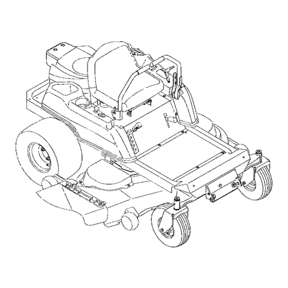
- Page 10 SECTION 1: CONTROLS AND FEATURES Figure 5 Deck Height Index J. Seat Adjustment Lever (Not Seen) Deck Lift Handle K. Fuel Tank Cap C. RH and LH Drive Control Levers L. Hour Meter/Indicator Panel M. Throttle Control D. Ignition Switch PTO Switch N.
- Page 11 NOTE: References to LEFT, RIGHT, FRONT, and E. Power Take-Off (PTO) Switch REAR indicate that position on the tractor when The PTO switch is located on the RH console to the facing forward while seated in the operators seat. rightof the operator's seat. A.
- Page 12 The hour meter/indicator panel is located on the LH engine while this indicator is illuminated. Contact console to the left of the operator'sseat. your Cub Cadet dealer to have the tractor and engine inspected. NOTE: The oil pressure indicator may illuminate...
- Page 13 N. Choke Control P. MODEL RZT 54 ONLY - Transmission Oil Expansion Reservoir The choke knobcontrolsthe positionof the engine choke. Pull the knob outto choke the engine; pushthe The transmission oil expansion reservoir is con- knob in to open the choke. nected by hoses to the RH and LH transmission assemblies, and is located beneath the seat box.
- Page 14 SLOW and FAST positions. for the protection of the operator. If the interlock system should ever malfunction, do not operate the tractor. Contact your authorized Cub Cadet Dealer. LH Control Lever RH Control Lever Out in Neutral Out in Neutrai •...
- Page 15 Have the tractor inspected by your Cub Cadet dealer. NOTE: Always remove the key from the ignition switch to prevent...
- Page 16 Adjust operator's seat most As the control levers are pushed farther forward comfortable position that allows you to operate the speed of the tractorwill increase. controls. seat adjustment in the ADJUSTMENTS section. DRIVING FORWARD • Release the parking brake. Faster •...
- Page 17 - Toturntotheright, m ove theright d rivecontrol IMPORTANT: Always maintain your grasp on the lever r earward oftheleftlever. S eeFigure 14. drive control levers. Do not release the levers to slow the tractor or to return to neutral FORWARD RIGHT TURN Turning While Driving Rearward To turn the tractor while driving rearward, move the control fevers as necessary so that one lever...
- Page 18 STOPPING THE TRACTOR Executing a Zero Turn ° Move both drive control levers to the neutral tractor MUST STOPPED. position to stop the motion of the tractor. WARNING: When executing a zero turn, Executing a zero turn while the tractor is °...
- Page 19 If a safety circuitis • Mow across slopes, not up and down. If mowing not working as designed, contact you Cub Cadet a slope, start at bottom and work upward to ensure turns are made uphill.
- Page 20 SECTION 3: ADJUSTMENTS ADJUSTING THE OPERATORS SEAT ° Reposition the control lever to align with the other set of holes in the pivot bracket and insert the • To adjust the positionof the seat, move and hold shoulder screw removed earlier. Fasten with the the seat adjustment lever toward the left.
- Page 21 All service work on the hydrostatic transmissions water or baking soda/water. should be performed by your Cub Cadet dealer. • NEVER connect (or disconnect) battery charger clips to the battery while the charger is turned on, as it can cause sparks.
- Page 22 CHARGING THE BA'n'ERY • Keep all sources of ignition (cigarettes, matches, lighters) away from the battery. The gas gener- Test and, if necessary, recharge the battery after the ated during charging can be combustible. tractor has been stored for a period of time. •...
- Page 23 • Using a pressure lubricating gun, lubricate the back through the larger circular opening of the front castor axles and pivot axle with Cub Cadet keyhole, then release the rod. 251H EP grease after every 10 hours of service. IMPORTANT: The tractor will not drive with the •...
- Page 24 • If the rotation stops, adjust the ferrule up or down • Tighten the jam nut against the console and repo- the control rod as necessary to align with the hole sition the control lever if necessary. in the transmission control arm, Re-insert the TRANSMISSION DRIVE BELT ferrule into the hole in the control arm and secure If the transmission drive belt becomes worn and...
- Page 25 TRACTOR STORAGE Emptying the fuel system: • Prior to putting the tractor in storage, monitor If your tractor is not going to be operated for an fuel consumption with the goal of running the extended period of time (thirty days to approximately fuel tank empty.
- Page 26 SECTION 5: MOWER DECK This section contains removal, installation, adjust- Rolling the belt off the PTO pulley. ment, and maintenance information for the mower • Using the deck lift handle, raise the deck to the deck. Some of the following information applies only...
- Page 27 Using care to prevent the front hanger rod from • Install the belt in the PTO pulley on the bottom of falling back into the deck bracket slots, carefully the engine. slide the cutting deck (from the right side) out •...
- Page 28 LEVELING THE MOWER DECK Front to Back Leveling. When correctly adjusted the mower deck should The front of the deck should be approximately level side to side, and the front of the deck should be inch lower than the rear of the deck. Adjust if neces- approximately 1/4 inch lower than the rear of deck.
- Page 29 ADJUSTING THE GAUGE WHEELS AND ROLLERS Using the lift handle, set the deck in the desired height setting, then check the gauge wheel distance from the ground below. If necessary adjust the front from discharge opening of the WARNING: Keep hands and feet away gauge wheels as follows: cutting deck.
- Page 30 DECK MAINTENANCE deck, be careful not to cut yourself on the Using the Deck Wash System ,_WARNING: When servicing the mower sharpened blades. The cutting blades must be kept sharp at all times. system, never engage the deck from any WARNING: When using the deck wash position other than the operator's seat of Sharpen...
- Page 31 REPLACING THE DECK DRIVE BELT Install the new belt around the spindle pulleys as shown in Figure 39 and reinstall the belt covers. • Remove the deck from beneath the tractor, (refer Route the belt rearward between the two idler to Deck Removal on page 26).
- Page 32 NOTE: Although the engine manual provides Kawasaki service contact information, always first contact your Cub Cadet dealer ff you experience engine problems or have questions regarding the engine. SAFETY AWARENESS Whenever you see the symbols shown below, heed their instructions! Always follow safe operat- ing and maintenance practices.
- Page 33 READ THIS FIRST For your safety,read this Owner's Manual and understandit thoroughly before operatingthis ENGINE. DO NOT run the engine in a closed area. Exhaust gas contains carbon monoxide, an odorless and deadly poison. Gasoline Is extremely flammable and can be explosive under certain condition. Stop engine and allow the engine to cool before refu_[ng.
- Page 34 Engine Emission Compliance Period Califomia All Other States Engines Greater Than 225 c¢ Engines Greater Than 225 c¢ Model Year - 2006 and later Model Year - 200t and later Durability period - 500 hours Durability Period - 1 000 hours (Category A) * tf your engi.e has an assigned emissio.s durability period it will be located on the certification label attached to the engine (IMPORTANT ENGINE INFORMATION).
- Page 35 FOREWORD We wishto thankyou for purchasing thisKawasakiengine. Pleaseread this Owner'sManualcarefullybeforestartingyour newengine sothatyouwillbethoroughly familiar withthe proper operation of yourengine's conb'ot, itsfeatures, capabilities and limitations, Alsoreadthe manualof theequipment t o whichthisengineisattached. To ensure a long, trouble-free life for your engine, give it the proper care and maintenance described in this manual.
- Page 36 8 GENERAL INFORMATION GENERAL INFORMATION Location of Safety Related Labels &WARNIItG 9E SPARKS, AXE|CLO_AR_A, TD_DN _Dr n_FLEI. FR ll!l VOlU| ¢ A. Warning El. Engine Maintenance GENERAL INFORMATION9 Location of Parts VIE_ F_04_04112 L Ek_tH_: Sta_er J. Voltage Regulator A+ Oil GaugetFtller B.
- Page 37 10 GENERAL INFORMATION Engine Serial Number Tune-up Specifications The engine serialnumber is youronly meansof ITEM ..SPeCifications ident_ing yourparticular enginefrom othersof the same modeltype. Ignition Timing Unadjustable This engine serial number is needed by your Spark Plugs: NGK BPR4ES dealerwhen orderingparts. 0.75 mm (0.030 in) Low Idle Speed 1 550 rlmin (rpm)
- Page 38 t2 FUEL AND OIL RECOMMENDATIONS FUEL AND OIL RECOMMENDATIONS ETHANOL: (Ethyl or Grain Alcohol) Fuel You may use gasoline containing up to 10% ethanol by volume. Use only dean, fresh, unleaded regular grade MTBE: (Methyl Tertiary Butyl Ether) gasoline. You may usegasoline containingup to 15% MTBE by volume.
- Page 39 14 PREPARATION PREPARATION • Levelthe enginebeforefueling, Fuel • Removethe fuel tank cap. • Slowlypour fuel into the tank throughthe fuel strainer, • Closethe tank cap securely. Gasoline is extremely flammable and can be explosive under certain condit_nso Before refueling, turn the engine switch to the OFF position.
- Page 40 16 STARTING STARTING Use fresh gasoline. Start Engine OProtect the engine or the equipment from direct exposure toweather when not in operation. OBefore startingthe engine, disconnectall possible [] LVLVl=I_t__II_[_ external loads. • Open the fuel valve (A) on the equipment. Exhaust gases contain carbon monoxide, •...
- Page 41 18 STARTING CAUTION • Puttheswitchkey (A)intothe engineswitch. • Turn theswitchkey totheSTART posiUon on the DO not run the electdc starter continuously equipment.Normallytheenginewillstartwithin3 for more than 5 seconds, otherwise the bat- seconds. tery may discharge quickly. If the engine does not start right away, wait 15 seconds and try again.
- Page 42 20 OPERATING Engine Inclination Thisenginewilloperateo_ntlnuousty at anglesup to 25=in any direction. Refer to the operatinginstructions of the equip ment this engTnepowers. Becauseof equipment design or application, t here may be morestringent restrictions regarding the angleof operation. CAUTION Do not operate this e.gine continuously at angles exceeding 2_' in any direction, En- gine damage could result from insufficient lubrication.
- Page 43 22 ADJUSTMENT ADJUSTMENT Twotypesofchokecontrol a re usedfor FH601V, the lever (C); insert 6 mm dia. pin (o_ 6 mm bolt) FH641V,FH661V,FH661V,FH680V,FH721VModel throughtwo holes. Engines. = Turn the choke setting screw (I) so that the clear- ance between the screw endand the tongueof the Associated Choke Type lever (J) iszero.
- Page 44 24 ADJUSTMENT • Move the equipment choke contro| to "CHOKE" Separate choke type position. Make sum that the carburetor choke valve (M) is completely closed. • Make sure that the choke valve turns from fully Throttle Cable Installation, Adjustment dosed position to fully opened pos_on when ac- •...
- Page 45 26 ADJUSTMENT Engine :Speed Adjustment N01_ 0 Do not tamper with the govemorsetttng or the car- buretor setting erthe carbu_tor settingto increase the engine speed. Every carburetor is adjusted at the factory and a cap or a Hop plate was _nstalied on each mixture #crew.
- Page 46 28 MAINTENANCE INTERVAL Eve Eve ''EVe E,e E,e MAINTENANCE First Daily 25 hr. 50 hr. lOOhr, 200 hr. 250 hr. 300 hr. 500 hr. 8 hr. *Check or clean air inlet screen. • .........._Clean dust and dirt from cylinder Kand cylinderhead fins.
- Page 47 30 MAINTENANCE • Install the oil drain plug. Oil Change • Remove the oil gauge and refillwith fresh oil (See FUEL AND OIL RECOMMENDATIONS chapter), Change oil after f_rst8 hours of operation. There* • Check the oil level (see PREPARATION chapter); after change oil eve_ 100 hours.
- Page 48 32 MAINTENANCE Air Cleaner Service Paper Element Clean the paper element (B) eve_ t00 hours, • Clean the element by tapping gently to remove Do not run the engine with the air cleaner CAUTION removed. dust. If very dirty,replace the element with a new one, •...
- Page 49 34 MAINTENANCE Cooling System Cleaning Before each operation, check that the air inlet (ro, tary) screen (A) is h'ee from grass and debris. Clean the screen if necessary. Ever/100 hours of oper- ago_o2__n check and clean the cooling fins and the in- side of engine shrouds to remove grass_chaff or dirt clogging the cooling system and causing overheat- ing.
- Page 50 36 STORAGE • Remove the sparkplugsand pourapprox t ~ 2 mL (0.06 ~ 0.1 cu in.) of engine oi! throughthe spark plug holes then screwthe spark plugsin after turn- ing the engine a few times, Slowlyturn the engine untilyou feel the compressionthen leave it there. Thistraps the air insidethe cylindersand prevents rust inside the engine, •...
- Page 51 38TROOUBLESHOOTING GUIDE Symptom ProbableCause Remedy Nospark or Faultysparkplugs Replace Spark plugs weak s park Faultyignition coils Engineswitchisin "OFF" position Turn engine switch to "STAR'P' position (See M) Engine Clean Clogged air cleaner overheats Air inlet screen or cooling air path clogged with dirt Insufficient engine oil Replenish or change oil...
- Page 52 40 WIRING DIAGRAM WIRING DIAGRAM //_//_////J////////////////////////////////////////////////, Wirin_ Diagram (With 12 V - 13 A Charging Coil) For electrical safety, always remove cable from negative (-) side of battery before at- tempting any repair or maintenance. Battery Capacity Recommended Battery Capacity Lawn Mower 12 V 200 CCA Class [Snow Thrower...
- Page 53 KAWASAKI LIMITED WARRANTY CALIFORNIA AND FEDERAL EMISSIONS CONTROL SYSTEMS SMALL OFF-ROAD ENGINES The California Air Resources Board, the Environmental Protection Agency (EPA) , and Kawasaki Motors Corp,, U.S.A, (hereinafter "Kawasaki") are pleased to explain the Emission Control Systems Warranty on your Kawasaki smalt off-road engine.
- Page 54 LIMITED LIABILITY. The liabilityof Kawasaki under this Emission Control Systems Warranty is limited soleiy to the remedying of defects in materials or workmanship by any authorized Kawasaki small off-road engine dealer at its place of business during customary business hours. This warranty does not cover inconvenience or loss of use of the small off-road engine or transportation of the small off-road engine to or from the Kawasaki dealer.
- Page 55 CALIFORNIA EMISSION CONTROL WARRANTY STAT EMENT YOUR W ARRANT'/RIGHTS AND OBLIGATIONS The California A ir ResourcesBoardand MTD Consumer G roupInc. are pleased to explainthe evaporative emission control s ystemwarrantyonyour 2007 lawn mower. In California, newlawn mowermustbe designed, builtand equipped to meetthe State'sstringent anti-smogstandards. M TD Consumer GroupInc. must warranttheEECS onyour fawnmowerfor theperiodof time listedbelowprovidedthere has beennoabuse, neglect o r impropermaintenance ofyour lawnmower.
- Page 56 CUB CADET MANUFACTURER'S LIMITED WARRANTY RESIDENTIAL ZERO-TURN ("RZT") MOWERS important:To obtainwarranty coverage owner must presentan Without l imiting theforegoing, t hislimited warranty d oesnot provide original p roofof purchase a ndapplicable maintenance records to coverage inthe following cases: the servicing dealer. Please see the operator's manualfor Routine m aintenance i tems suchas lubricants, filters,blade information onrequired m aintenance a ndserviceintervals.
- Page 57 Puede obtenor un amortiguador de chispas para el silenciador a tray,s de su distribuidor de motores autorizado rn&s cercano o ponerse en contacto con el departamento de servicios, P.O. BOx 361131 Cleveland, Ohio 44t36-0019. CUB CADET P.O. BOX 361131 CLEVELAND, OHIO 44136-0019 [www.cubcadet.com]...
- Page 58 CONTENIDO PREPARACION DEL TRACTOR ................... MEDIDAS IMPORTANTES DE SEGURIDAD ................ CALCOMAN|AS Y ET1QUETAS DE SEGURIDAD ..............INDICADOR DE PENDIENTES ....................tNDICAClONES PARA EL PROPIETARIO ................LLAMADAS DE INFORMACION SOBRE SERVICtO ............. REGISTRO DEL NUMERO DE MODELO Y DEL NOMERO DE SERIE .......
- Page 59 POSICION DE LAS PALANCAS DE CONTROL DE LA CONECTE LA BATER_ TRANSMISION accesorios de la bater_a contienen plomo y Las palancas de control de la transmisi6n del tractor se ADVERTENCIA: postes, bomes compuestos de plomo. Ldvese las manos bajan para el embarque. Para hacerlo, se quitan la despu_s de estar en contacto con estos tuerca de seguridad con brida, el tornillo hexagonal y la componentes.
- Page 60 AVERTENCIA • El escape del motor de este producto, algunos de sus componentes y algunos componentes del vehiculo contienen o liberan sustancias quimicas que e! estado de California considera que pueden producir c&ncer, defectos de nacimiento u otros problemas reproductivos. •...
- Page 61 22. Para esta m,_quina use enicamente accesorios aprobados por Cub Cadet. Lea, comprenda y siga todas ]as instrucciones proporcionadas con los...
- Page 62 5. Nopermita n unca queniSos m enores de14afios Use todos los elementos de protecci6n que se operen estam_.quina. LosniSos de 14 aSoso indican en este manual. mayores s olamente debedan o perar ia mdquina Despues de golpear un objeto extraSo, detenga el bajo laestrica s upervisi6n delospadres y despu_s motor, retire el cable de la bujia e inspeccione derecibir instrucciones...
- Page 63 CALCOMANfAS Y ETIQUETAS DE SEGURIDAD Mantenga limpios los grdficos (calcomanfas) de seguridad de los productos.Vuelva a colocar cualquier grdfico de seguddad que est_ daSado, destruido, que falte o que haya sido pintado o no se pueda leer. Podr& obtener grdficos de seguridad de reemplazo a trav_s de su distribuidor.
- Page 64 USE ESTA P,8,GINA COMO GUfA PARA DETERMINAR LAS INCLINACIONES DE LAS PENDIENTES EN LAS QUE PODR|A NO TENER UNA OPERACION SEGURA. II|_ MIRE Y MANTENGA ESTE NtVEL CON UN _,RBOL VERTICAL "_ LA ESQUINA DE UN EDIFICIO 0 UNA CERCA 15 °...
- Page 65 Lfnea de Asistencia al Cliente de Distribuidores flamando al n_mero 1-877-282-8684 O pSngase en contacto con Cub Cadet a traves de lntemet, accediendo a nuestra p_.gina Web: www.cubcadet.com Para obtener un 6ptimo...
- Page 66 SECCION 1" CONTROLES Y CARACTER|STICAS Figura 5 Posicionamientode la altura de la plataforma J. Palanca de ajuste del asiento (no se ve) Manija de elevaci6n de la plataforma K. Tap6n del dep6sito de combustible Palancas de control de transmisi6n L. Medidor horarioiPanel indicador LADO DERECHO y LADO IZQUIERDO M.
- Page 67 NOTA: A menos que se indique especificamente Interruptor de la potencia de arranque (PTO) contrario, las referencias a IZQUIERDA, DERECHA, El interruptor de la potencia de arranque (PTO) est_ ADELANTE Y A TRAS indican esa posici6n relativa ubicado en la consola del lado derecho, a la derecha deJ desde el asiento del operador en el tractor, mirando asiento del operador.
- Page 68 P6ngase El medidor horario/panel indicador esta ubicado en la contacto con el distribuidor Cub Cadet para que se consola del lado izquierdo, a la izquierda del asiento del realice la inspecci6n del tractor y del motor. operador. NOTA:...
- Page 69 N. Control del cebador P. MODELO RZT 54 UNICAMENTE - Dep6sito de expansi6n del aceite de transmisi6n La perilla del cebadorcontrola la posici6n del cebador del motor.Tirede la periflahacia afuerapara cebar el El dep6sitode expansi6ndel aceitede transmisi6nestd motor; tire de la perilfahaciaadentropara abrirel conectado por mangueras a los conjuntos de cebador.
- Page 70 P6ngase contacto distribuidor Palanca de control de] Palanca de control del ]ado autorizado Cub Cadet. derecho hacia afuera ]ado izquierdo hacia afuera en neutral • El sistema de bloqueo de seguridad evita que el motor en neutral...
- Page 71 Haga • Gire la Ilave de encendido posici6n "OFF" controlar el tractor por el distribuidor Cub Cadet. (apagado) y quite la Ilave interruptor encendido. ARRANQUE...
- Page 72 • Ajuste el asiento del operador a la posici6n m&s c6moda permita operar controles. CONDUCCION HACIA ADELANTE Consulte forma hacerlo la secci6n AJUSTES. Mds r&pido ° Suelte el freno de mano. • Coloque las palancas de control de transmisibn del lado derecho y del lado izquierdo hacia adentro, en posici6n neutral.
- Page 73 - Para girar a ta derecha, mueva la palanca de IMPORTANTE: Siempre tome mantenga control de! ]ado derecho hacia atr_s respecto de palancas de control con firmeza. No suelte la palanca izquierda+ Vea Figura 14. palancas para que el tractor se desplace con mayor lentitud ni para volver a posici6n neutral.
- Page 74 Giro de radio cero Presione el interruptor de la potencia de arranque (PTO) hacia abajo a ]a posici6n desenganchada, ADVERTENCIA: Para realizar un giro de radio cero, el tractor SE DEBE DETENER. Use la manija de elevaciSn de la plataforma para La realizaci6n de un giro de radio cero con levantar la plataforma a su posici6n m_,s alta, el tractor...
- Page 75 Si corta el c6sped en distfibuidor Cub Cadet para que inspeccione el tractor. pendiente, comience la base y desplacese NO use el tractor si algen circuito de seguridad no est&...
- Page 76 SECCI( N 3: AJUSTES AJUSTE DEL ASIENTO DEL OPERADOR • Vuelva a colocar la palanca de control en posici6n afineada con los otros juegos de odficios Para ajustar la posiciSn del asiento, mueva soporte de pivote e inserte el tornillo con reborde sostenga la palanca de ajuste del asiento hacia la que quit6 antes.
- Page 77 SECCION 4: MANTENIMIENTO MANTENIMIENTO DEL MOTOR Modelo RZT 54 0NICAMENTE El modelo RZT54 estd equipado con un dep6sito de En la copia del manual del motor que se encuentra al expansi6n del aceite de transmisi6n. En condiciones final este manual pueden encontrar operativas normales, no es necesario controlar el nivel...
- Page 78 CARGA DE LA BATERIA • Mantenga todas fuentes combustiSn (cigarrillos, cerillas, encendedores) alejadas de la Si et tractor ha estado guardado durante un tFempo, bateria. El gas generado durante ra carga puede ser pruebe ta batefia y, si es necesario, recdrguela. combustible.
- Page 79 Con una pistola de lubdcaci6n a presi6n, fubrique la varilla. los ejes de las ruedas pivotantes delanteras y el eje de pivote con grasa Cub Cadet 251H EP cada 10 IMPORTANTE: E1 tractor no funciona si las varillas horas de servicio.
- Page 80 alinearla c on el orificio CORREA DE TRANSMISION del brazo de control de transmisi6n. Vuelva a insertar la ferula en el orificio Si la correa de transmisi6n se desgasta y hace que las del brazo de control y ffjela con el pasador transmisiones se deslicen es necesario reemplazarla.
- Page 81 GUARDA DEL TRACTOR • Haga funcionar el motor hasta que comience deteneme. Use el cebador para mantener Si el tractor no a va a funcionar por un perfodo motor en funcionamiento hasta que se haya prolongado (desde treinta dfas hasta aproximadamente agotado todo el combustible del carburador.
- Page 82 SECCION 5: PLATAFORMA DE LA CORTADORA DE ClaSPED Esta secciOn contiene informaciOn sobre el retire, la Haciendo rodar la correa para sacarla de la polea de instalaci6n, el ajuste y el mantenimiento de la plaforma la potencia de arranque (PTO). de la cortadora de cdsped.
- Page 83 8. Con cuidadopara evitar que ta varilla de mayor recorrido horizontal de la correa entre las suspensi6n delantera caiga hacia atr_.s d entro de poleas !ocas de la plataforma y la polea de la lasranuras delsoporte delaplataforma, deslice c on potencia de arranque en la parte inferior del motor.
- Page 84 NIVELACION DE LA PLATAFORMA DE LA NivelaciOn adelante atr_s. CORTADORA DE CESPED parle frontal plataforma debe estar aproximadamente ¼ de putgada ma,s abajo que la parle Cuando encuentra correctamente ajustada, posterior. De set necesario, reatice un ajuste de la plataforma de la cortadora de c_sped debe estar...
- Page 85 en el valor de altura deseado. AJUSTE DE LAS RUEDAS CALIBRADORAS Y LOS RODILLOS Los rodillos traseros de la pFataforma se pueden fijar er_ posici6n baja o alta. Usando la manija de elevaci6n, fije la plataforma en el pies alejados de la abertura de descarga de ADVERTENC|A: Mantenga las manos y los valor de altura deseado, luego controle la distancia entre...
- Page 86 MANTENIMIENTO DE LA PLATAFORMA mantenimiento de la plataforma de la Uso deesistema de lavado de la plataforma ADVERTENCIA: Cuando realice cortadora de c_sped, tenga cuidado para no cortarse con las cuchillas filosaso lavado de la plataforma, nunca enganche la ADVERTENCIA: Cuando use el sistema de Las cuchillas de corte deben estar siempre afiladas.
- Page 87 REEMPLAZO DE LA CORREA DE TRANSMISION Instale la nueva correa alrededor de las poleas del DE LA PLATAFORMA husillo tal como se muestra en Figura 39 y reinstale las cubiertas de la correa. Retire plataforma desde abajo tractor Oriente la correa hacia atr&s entre tas dos poleas (consulte Retiro de la plataformaen la p_.gina 26).
- Page 89 GARANT|A LIMITADA DE KAWASAKI SISTEMAS DE CONTROL DE EMISIONES DE CALIFORNIA Y FEDERAL MOTORES PEQUENOS PARA EQUIPO TODO TERRENO Ef Departamento de los Recursos de Aire de California, la Agencia de Protecci6n Ambiental de los Estados Unidos y Kawasaki Motors Corp., U.S.A. (en adefante, "Kawasaki") se complacen en explicar la garantfa de tos sistemas de control de emisiones de su motor pequeSo para equipo todo terreno Kawasaki.
- Page 90 RESPONSABILIDAD LIMITADA. La responsabitidad de Kawasaki segt]n esta Garantia de los Sistemas de Control de las Emisiones se limita exclusivamente a la soluci6n de defectos de materiales o mano de obra pot parte de cualquier distribuidor de motores pequefios para equipo todo terreno Kawasaki autorizado, en su lugar de operacibn, durante e] horario habitual de actividades.
- Page 91 DECLARACION DE GARANT|A DE CONTROL DE EMISIONES DE CALIFORNIA DERECHOS Y OBLIGAClONES DE SU GARANT|A El Consoledo RecursosAGreesde California y MTD ConsumerGroupinc. se compiacenen explicar la garnntiadot sistema de control de emisiones per evaporaciGnde su cortadorade c_sped2007. En California, las nuevasm_quinas pare cortar c_spedso deben disefiar, construiry equipar de mode de cumplir conias rigurosasnorrnascentre la poluciGndel estado.MTD ConsumerGroupInc.
- Page 92 CUB CADET GARANTfA LIMITADA DEL FABRICANTE PARA CORTADORAS DE CF-SPED RESIDENClALES DE RADIO DE GIRO CERO ("RZT") IMPORTANTE: Pareobtenercoberlurade garanffa, e l propietario Sinlimitaci6n de Ioanteriormente dicho,estagarantia limitadano debepresenter unaevidencia original d e lacompra y los registros ofrececobertura en lossiguientes casos:...