Table of Contents
Advertisement
Save This Manual
For Future Reference
A/RS
owners
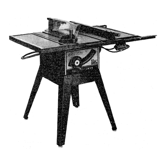
manual
MODEL NO,
113.241680
SAW WITH LEGS
TWO TABLE
EXTENSIONS
AND MOTOR
Serial
Number
Model
and serial
number
may be found
at the rear of the base.
You should
record
both
model
and serial number
in a safe place for
future
use.
CAUTION:
READ
ALL
INSTRUCTIONS
CAREFULLY
MRN
IO-INCH
FLEX DRIVE
TABLE SAW
• assembly
• operating
• repair
parts
Sold by SEARS, ROEBUCK
AND CO., Chicago,
Part No. 62868
IL. 60684
U.S.A.
Printed
in U,S.A
Advertisement
Table of Contents

Related Manuals for Craftsman 113.241680


Summary of Contents for Craftsman 113.241680
- Page 1 Save This Manual For Future Reference A/RS owners manual MODEL NO, 113.241680 SAW WITH LEGS TWO TABLE EXTENSIONS AND MOTOR Serial Number Model and serial number may be found at the rear of the base. You should record both model and serial number in a safe place for IO-INCH...
- Page 2 FULL ONE YEAR WARRANTY ON CRAFTSMAN TABLE SAW If within one year from the date of Purchase this Craftsman Table Saw fails due to a defect in material or workmansnip, _ears will repair'it, free of charge. WARRANTY SERVICE IS AVAILABLE...
- Page 3 AE)DJTIONAL SAFETY aNSTRUCTiONS FOR TABLE SAWS operating immediately until the particular WARNING: FOR YOUR OWN SAFETY, DO NOT part is properly repaired or replaced. OPERATE YOUR SAW UNTIL iT iS COMPLETELY Small loose pieces of wood or other objects ASSEMBLED AND iNSTALLED ACCORDING that contact the rear of the revolving blade...
- Page 4 when ripping, use the maximum diameter blade Provide adequate support to the rear and sides of the saw table for wider or long for which the saw is designed, since under these conditions the spreader is nearest the blade. work pieces. O.
- Page 5 MOTOR SPECJFICATmONS ELECTRmCAL REQUIREMENTs This saw is designed to use a 3450 RPM motor only. This saw is equipped with a 3-conductor cord and Do not use any motor that runs faster than 3450 grounding type plug which has a grounding Prong, RPM It is wired for operation on 110-120 volts, 60...
- Page 6 CONTENTS WARRANTY ......... Tilt Handwheel ......GENERAL SAFETY INSTRUCTION Tilt Lock Handle ......Rip Fence ......... • , Miter Gauge ......Blade Guard ......Table Insert ......Removing and installing Sawblade ..Exacti-Cut ........ Tools Needed ......BASIC SAW OPERATION USING THE MITER List of Loose Parts ......
- Page 7 LISTOFLOOSE PARTS Part Hame item Qty. Item Part Name Qty. A Blade Guard and Spreader ..... Loose Parts Bag No. 62745 .... B Rip Fence ......(Containing the Following Items): C Owners Manual ...... Bracket, Corner Support ..D Miter Gauge ......Bracket, Corner Stiffener ..
- Page 8 Part Mame Qty. item Item Part Name Qty. Loose Parts Bag No. 62889 ... Loose Parts Bag No. 62891 ... (Containing the Following Items): (Containing the Following Items): Nut, Weld ...... Bolt, Carriage 1/4-20 x 3/4 ..Clamp, Spreader ....Screw, Soc.
- Page 9 MOUNTING 1. From among the loose parts, find the following hardware: 4 Hex Head Screws, 5/16 - 18 x 1-1/4 in. long. 4 Hex Nuts, 5/16- 18 (approx. dia. of hole 5/16 in.) 4 Lockwashers, 5/16 in. External Type (approx. dia.
- Page 10 iMPORTANT m Read Before Proceeding Blade cannot be more than 2 inches above the table top when tilting the sawblade to make bevel cuts or adjustments. Lower blade to 2 inches or closer to the table top to tilt the saw. Failure to do this may LOCKWASHER result in damage to your saw.
- Page 11 HEELING ADJUSTMENT or PARALLELISM MARK'X"ON TOOTH OF SAWBLADE TO MITER GAUGE GROOVE While cutting, the material must move in a straight line PARALLEL to the SAWBLADE . . . therefore both the miter gauge GROOVE and the RIP FENCE must be PARALLEL to the SAWBLADE.
- Page 12 BLOCK WOOD .9. Using a wood block and hammerasshown, move rear support bearing to right or left as required to realign the blade. If necessary, shift front support bearing in similar manner; but do NOT move front support bearing unless necessary. Recheck the alignment with...
- Page 13 If blade is NOT SQUARE to table.., the 90 ° stop screw must be ADJUSTED. A. Unscrew 90° STOP SCREW three to four turns using 3/16 in. setscrew wrench. B. Turn tilt handwheel clockwiseoneturn, then turn handwheel counterclockwise until blade square with table.
- Page 14 TILT MECHANISM TILT HANDWHEEL Lower blade to 2 inches or closer table before tilting blade. Failure to do this result damage to your saw. The handwheel should turn freely without binding. The turning action can be adjusted by tightening loosening the screws in the bearing retainer.
- Page 15 THESE EDGES EVEN 5. From among the loose parts, find the following hardware: 4 Carriage Bolts, 5/16 - 18 x 3/4 in. long 4 Flatwashers 17/64 x 3/4 x 1/16 4 Hex. Nuts, 5/16 - 18 (approx. dia. of hole 5/16 in.) 4 Lockwashers, 5/16 in.
- Page 16 ARBOR MOTOR ---_ 5. Remove the plasticcoversfromthe endsofthe SHAFTHOUSING. 6. Push the saw arbor end of the flexible shaft out SHAFT HOUSING until approximately 1 inch above of the SMALL FERRULE. PULL FLEXIBLE SAW ARBOR SHAFT 1" L_.J 7. Insert the flexible shaft assembly...
- Page 17 CAREFULLY ROTATE BLADE HAND LINE SQUARE OF FLEXIBLE SHAFT WITH SQUARE HOLE 9. Bend the SHAFT HOUSING toward the motor MOTOR CQNNECTOR as illustrated. Insert end of LARGE FERRULE over MOTOR CONNECTOR line SQUARE END of flexible shaft with square hole in MOTOR CONNECTOR.
- Page 18 14.CAUTION:Overtightening shaft bracketbolts maycausedamage to bracketor ferrule. With end of LARGEFERRULE insertedinto recess in motor end cap tighten 2 Hex Head nuts on shaft brackets. LARGE FERRULE must be pushed against the motor end cap as faras it will go. Tighten nuts but do not OVERTIGHTEN.
- Page 19 Insert four (4) 5/16-18 x 1-1/4 in. long screws through holes in each EXTENSION then through table. Install flat washer, Iockwashers, and nuts on the screws... DO NOT TIGHTEN. Align front edge of extension with front edge of saw table. Pull Extension UPWARDS...
- Page 20 5_Turn front bar end for end and insert bolts througr_ holesin m_ddle andon right sidesof front of saw tabte as i!lustrated . . install !ockwashers nuts DON'T SCREW NUTS ON ALL THE WAY. just get them started on the sCreWS. @..._ SELF-THREADING HOLE OR 5TH...
- Page 21 13, Raise blade a!! the way _p, !4. Carefuiiy move fence against blade. !5. Move front untit "0" mark on rip scale approximately in line with indicator. 16. Move FRONT upwards until fence approximately 1/32 in, above table., , tighten screw at left end of bar, NOTE;...
- Page 22 For very close adjustments, grasp the guide bar with both hands and move the fence with your thumbs. Place fence on saw but DO NOT LOCK IT. Move the REAR END of the fence slightly to the right or left . . . when you release it, the fence should \ "spring"...
- Page 23 HEX SCREWS FENCE HEAD 3. The rip fence must be PARALLEL with sawblade and miter Gauge grooves Move fence until it is along side of groove. Do NOT LOCK IT. it should be parallel to groove, If it is not; A.
- Page 24 BLADE S©UARE W_TH TABLE WARNIlNG: AVOID iNJURY DUE; ACCIDENTAL START. TURN SWITCH "OFF" REMOVE PLUG FROM POWER SOURCE O UTLET. 2, MAKE SURE THE BLADE IS ALL THE WAY UP AND SQUARE WtTH THE TABLE 3 Posit_on SPREADER SUPPORT on rod until it Js even w_h the cod of the rod.
- Page 25 SPACE EQUAL TO APPROX_ WOOD 3 THICKNESSES OF PAPER KERr ALIGNING SPREADER WARNING: AVOID _NJURY FROM BLADE ACCIDENTAL START, TURN SWITCH OFF AND REMOVE PLUG FROM POWER OUTLET. IMPORTANT: SPREADER must always PARALLEL to the sawblade and in the MIDDLE the cut (KERr) made by the sawblade, NOTE:...
- Page 26 4. if the head is not square with the bar, adjustments are required, A. Loosen the "knob" (1) and the "two screws" (2), B. Position the HEAD square with the BAR using a combination square. C. PUSH the STOP PiN into theslot in the head a t "0"...
- Page 27 GETTING TO KNOW YOUR SAW SAWBLADE BLADE GUARD TABLE,NSERT M,TER OAUGE 10EXACT-I-COT > ANT'Z'C@CK LOCK HANDLE _ _.._._iit_.._ ATTACHING FACING 4" TILT LOCK HANDLE "_,._'_' (UNDERNEATH TABLE) ELEVATION HANDWHEEL TILT HANDWHEEL ON-OFF SWITCH ON-OFF SWITCH CAUTION: Before turning switch on, make sure the blade guard is correctly...
- Page 28 ELEVATION HANDWHEEL , . . elevates MITER GAUGE _ . nead is locked in position lowers the blade. Turn clockwise to elevate... for crosscutting or mitering by tightening counterclockwise to lower. lock knob. ALWAYS LOCK IT SECURELY WHEN tN USE, NOTE: Any time sawbiade has been...
- Page 29 BLADE GUARD SHOWN FOR PICTURE CLARITY NEVER OPERATE WITHOUT PROPER !NSERT PLACE. BLADE iNSERT WHEN SAWING,.. USE THE COMBINATION DADO MOLDING INSERT 22271) WHEN DADOING OR MOLDING. BLOCK ARBOR i ,, ARBOR LOOSE COLLAR ARBOR ';7.,'>D , SCREW ARBOR TEETH POINTING TO _-_ FRONT...
- Page 30 BASIC SAW OPERATmON THESE EDGES MuST WORK HELPERS 3/4 PLYWOOD BE PARALLEL Before cutting any wood on your saw, study all of the "Basic Saw Operations". l- 4-3/4 - F'-- Notice that in order to make some of the cuts, it is necessary to use certain devices "Work...
- Page 31 WORKPIECE CROSSCUTTING CROSSCUTTING is known as cutting wood across the grain, at 90 ° , or square with both the edge and the flat side of the wood. This is done with miter gauge set at "0". TAB LE graduations miter gauge provide...
- Page 32 1. NEVER USE THE RIP FENCE AS A LENGTH STOP BECAUSE THE CUTOFF PI ECE COULD BiND BETWEEN THE FENCE AND THE BLADE CAUSING A KICKBACK. BLOCK 2. When making repetitive cuts shorter than 6 in., clamp a block of wood 2 in. long tothe table to act as a length stop.
- Page 33 made at an angle other than 90 ° to both the edge COMPOUND MATER CUTTING and the flat side of the wood. COMPOUND MITER CUTTING is a combination Adjust the miter gauge and the blade to the desired miter cutting and bevel crosscutting.
- Page 34 When "WIDTH OF RIP" is 6 in. and WIDER use your RIGHT Handto feed the workpiece until it is clearof the table. Use LEFT hand ONLY to guide the workpiece ... do not FEED the workpiece with the left hand. When "Wi DTH OF RIP"...
- Page 35 Feedthe workpiece by handalongtheAUXILIARY FENCE untilthe endis approx.1 in. pastthe front edgeof thetable.Continue tofeedusingthe PUSH BLOCK. Holdtheworkpiece in positionandinstall t he PUSH BLOCK by sliding it on top of the AUXILIARY FENCE/WORK SUPPORT (ThisMayRaise Guard). BAFFLE Narrow stripsthickerthantheAuxiliaryFence/Work Supportmayenterthe guardandstrikethe baffle. CAREFULLY raiseguardonlyenough to clearthe workpiece.
- Page 36 PLOUGHING AND MOLDING PLOUGHING is grooving with the grain the long MOLDING is shaping the workplece with the grain way of the workpmece, using the fence. USE proper the long way of the workpiece, using the fence. Use holddowns and feed devices. proper hoiddowns and feed devices.
- Page 37 DADOING instructions operating Dado Head contained in booklet furnished with the Dado Head. Recommended Dado Head is listed under Recommended Accessories in this manual. The arbor on the saw, is only long enough so that the widest cut that can be made is 13/16" wide. It is not necessary to install the outside loose collar before screwing on the arbor nut.
- Page 38 Frequently blow out any dust that may accumulate inside the saw cabinet and the motor. Frequently clean your cutting tools with Craftsman Gum and Pitch Remover. A coat of automobile-type wax applied to the table will help to...
- Page 39 (First 1. Remove the core from the casing, clean the core Clean with Craftsman Gum & Pitch Remover.) washing with kerosene approved solvent. 3. Cradle bearing points. 4. Bearing points in guard assembly, miter gauge Dry, the core.
- Page 40 TROUBLE SHOOTUNG WARNING: TO AVOID INJURY, TURN SWITCH "OFF" AND ALWAYS REMOVE PLUG FROM POWER SOURCE OUTLET BEFORE TROUBLESHOOTING. TROUBLE SHOOTING == GENERAL PROBABLE CAUSE REMEDY TROUBLE 1. Discard Blade and use a different blade. 1. Blade out of balance. Excessive vibration.
- Page 41 TROUBLE SHOOTING -= MOTOR {Continued) TROUBLE; PROBABLE CAUSE REMEDY Motor starts slowly 1. Low voltage will not 1. Request voltage check from the power or fails to come up trip relay. company. to full speed. 2. Windings burned out 2. Have motor repaired or replaced. or open.
- Page 42 15 14 47 15 14 _-----52 Figure...
- Page 43 PARTS LiST FOR CRAFTSMAN 10 iNCH TABLE SAW MODEL NO, 113,241680 FIGURE -Key Part Part Description Description 62894 STD523107 Guard Assembly, Saw (See Fig. 5) *Screw, Hex Hal. 5/16-18 x 5/8 STD532507 STD523117 *Screw, Hex Hd. 5/16-18 x 1-3/4 *Bolt, Carriage...
- Page 44 PARTS LIST FOR CRAFTSMAN 10 INCH TABLE SAW MODEL NO. 113.241680 45 46 / J52 38 37 Figure 2...
- Page 45 PARTS LiST CRAFTSMAN 10 iNCH TABLE MODEL 113.241680 FIGURE Part Part Description Description *Screw, Pan Cross 10-32 x 3/8 STD523110 *Screw, 5/16-18 x 7/6 iSTD601103 '37829 Screw, Clamp STD551131 *Lockwasher, 5/16 Handle 62885 Support, Bearing Nut, Bevel Pivot 60537 Washer, .505 x 47/64 x 1/16...
- Page 46 PARTS LIST FOR CRAFTSMAN 10 iNCH TABLE SAW MODEL NO, 113.24t680 FIGURE 3 -- 62773 FENCE ASSEMBLY Description 62773 = Fence Assembly', Rip Key No. 1) STD551031 Washe , 21/64 I.D. * Standard Hardware Item =-- May Be Purchased Locally.
- Page 47 PARTS LiST FOR CRAFTSMAN 10 iNCH TABLE SAW MODEL NO. 113.241580 "-------4 FIGURE 4 -- MITER GAUGE ASSEMBLY Part Description 62704 +Gauge Assembly, Miter 62693 Plug, Button 62692 Knob, Miter Gauge (Included Key No. 1) *Washer, Plain 21/64 x 1 x 1/16...
- Page 48 LiST FOR CRAFTSMAN 10 raNCH TABLE SAW MODEL NO. 113,24168G FIGURE 5 m ON/OFF POWER OUTLET 60381 ]Key" Part " t No. Description 60381 J oOn/Off Power Outlet Complete 60375 Cord, Molded 60380 Housing, Switch !60256 Key, Switch • Does Not Include...
- Page 49 PARTS LIST FOR CRAFTSMAN 10 iNCH TABLE SAW MODEL NO, 113=241680 FIGURE 6 m GUARD ASSEMBLY Part Description 62894 Guard, Assembly, 60297 Nut, Push 62391 Pin 1/4 x 1-1/2 62395 Support, Guard 62389 Guard, Saw 62390 Pin, 1/4 x 1-3/4...
- Page 50 PARTS LiST FOR CRAFTSMAN 10 iNCH TABLE SAW MODEL NO, 113.24!580 FIGURE 7 -- LEGS Part Description 60314 Screw, Serrated Truss 1/4-20 x 5/8 62552 62554 Stiffener, Side STD551225 *Lockwasher, Ext. 1/4 STD541025 *Nut, Hex 1/4-20 62553 Stiffener, STD541250 *Nut,...
- Page 51 PARTS LiST FOR CRAFTSMAN 10 iNCH TABLE SAW MODEL NO. 113.241680 NOTE: ANY ATTEMPT TO REPAIR THiS MOTOR MAY CREATE A HAZARD UNLESS REPAIR IS DONE BY QUALIFIED _)_..---5 SERVICE TECHNICIAN. REPAIR SERVICE IS AVAILABLE AT YOUR NEAREST SEARS STORE.
- Page 52 10 iNCH FLEX DRIVE TABLE SAW SERVICE Now that you have purchased your 10-inch table saw should a need ever exist for repair parts or service, simply contact any Sears Service Center and most Sears, Roebuck and Co. stores. Be sure to provide all pertinent facts when you call or visit.