Table of Contents
Advertisement
Save ThisManual
For Future Reference
A/RS
owners
manual
MODEL NO.
113.2472t0
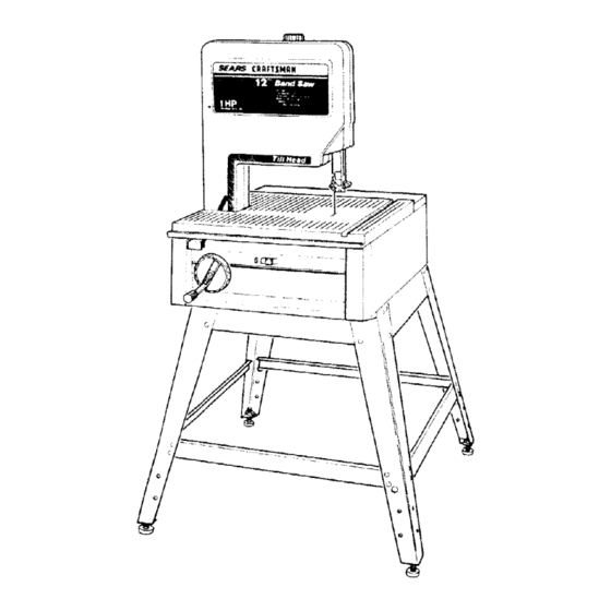
BAND SAW WITH
LEG SET
MODEL NO.
1t3.2473t0
BAND SAW WITH
CABINET
S_rial
Number
__
Model and serial numbers
may be found
at the
left-hand
side of the base.
You should record both
model and serial number
in a safe place for future
USe.
im N
CAUTION:
READALL
INSTRUCTIONS
CAREFULLY
113.247310
113.24 7210
CRRFTSMRN
12-1NCH BAND SAW
• assembly
• operating
• repair parts
_,.
j
.....
_,'
Sold by SEARS, R OEBUCKAND CO., Chicago, IL 60684 U.S.A.
Part No. SP5086
Printed in U.S.A
Advertisement
Table of Contents

Related Manuals for Craftsman 113.2472T0


Summary of Contents for Craftsman 113.2472T0
- Page 1 Save ThisManual For Future Reference A/RS owners manual MODEL NO. 113.2472t0 BAND SAW WITH LEG SET MODEL NO. 1t3.2473t0 BAND SAW WITH CABINET S_rial Number Model and serial numbers may be found at the left-hand side of the base. You should record both...
-
Page 2: For Power Tools
FULL ONE YEAR WARRANTY ON CRAFTSMAN If within one year from lhe date of purchase, this Craftsman Band Saw fails due to a defect in malarial or workmanship, Sears will repair it, free of charge. WARRANTY SERVICE IS AVAILABLE CENTER/DEPARTMENT THROUGHOUT This warranty applies only while this product is used in the United States. -
Page 3: For Band Saw
Adjust the saw so the table is level and the saw does not rock. c. Bolt the saw to the floor if it tends to slip, slide, or tip over during operations heavy boards. d. Turn saw off and unplug electric moving the saw to a new area. - Page 4 1. Choose the right size and style blade for the material and the type of cutting you plan to do. Use this band saw to cut and sand only wood, wood like products 2. Make sure the blade teeth point downward toward the table.
-
Page 5: Table Of Contents
Sawblade Path properly The area of the worktable line with the saw blade. The distance the tip of the saw blade tooth is bent outward from the face of the blade. Trailing End The workpiece Workpiece The item on which the cutting performed. - Page 6 POWER SUPPLY Motor Specifications The A-C motor used in this saw is a capacitor-start, non-reversible type having the following specifica- tions: MODEL NO.MODEL 113.247210 Rated H.P ... Maximum Developed H.P. Voltage Amperes Hertz (Cycles) ... Phase ... Single RPM ...
-
Page 7: Contents
SOCKET WRENCH SHOULD SQUARE WARNING: SHOCK, DO NOT NOT ATTEMPT SAW, PLUG IN THE POWER CORD, OR TURN THE SWITCH ON UNTIL THE MISSING PARTS WHENEVER ARE OBTAINED RECTLY. Remove front table and front cover first while saw is being cover, pull the cover at the neck and underside th roat area. - Page 8 NOTE: To avoid damage to the band saw leave it laying on its left side until you are ready to mount it to the leg set or cabinet. To prevent scratching finish, lay a piece of the packing box under the saw. TABLE OF LOOSE...
- Page 9 LIST OF LOOSE PARTS IN BAG #507657 MODEL 113.247210 ITEM DESCRIPTION Truss Head Screw 1/4-20 x 1/2 ... Lockwasher Ext. 1/4 ... Hex Nut 1/4-20 ... Leveling Foot ... Hex Jam Nut 3/8-16 LIST OF LOOSE PARTS IN BAG #507655 MODEL 113.247210 &...
- Page 10 3. Attach four (4) leveling feet to bottom of each leg as illustrated. Hand tighten 4. Put leg set in area intended for use of saw. With a 7/16-inch wrench or socket, securely tighten all bolts. Adjust leveling feet.
- Page 11 ASSEMBLING CABINET Model 113.247310 1. Separate all "loose" parts from packing materials and check each item with "Parts List" to make sure all items are accounted ing any packing material. From loose parts find the following ITEM DESCRIPTION Right Side Panel ... Left Side Panel ...
- Page 12 FEET MUST BE ADJUSTEO THAT SAW DOES NOT ROCK. 10. To adjust leveling feet so the saw will sit properly: a. Move saw to desired location. b. With 9/16-inch wrench loosen bottom nut. c. Back off top nut by hand.
- Page 13 M Wing Nut 5/16-18 ... Belt Tension Stud ... Motor Pulley w/Set Screw ... Poly "V" Belt ... 2, Have the band saw positioned unpacked, To prevent scratching piece of the packing box under the saw. 3. Place the three (3) spacers onto the three motor studs as shown.
- Page 14 7. Carefully position the motor so that the poly "V" belt is around the motor pulley motor studs align with the slots in the motor mount. 8, Push motor studs through and install the flanged lock nuts to the three (3) motor spacers.
- Page 15 This is the motor cord. WARNING: FOR YOUR OWN SAFETY, NEVER PLUG 1=HE SAW IN UNTIL STEPS ARE COMPLETED. 2. Loosen the two screws holding box cover on the back side of the motor. Swing the cover open.
- Page 16 A Truss Head Bolts 1/4-20 x 112 ... B Lockwashers External 1/4 ... C Hex Nuts 1/4-20 ... 2. Place saw on cabinet so that holes in bottom of saw line up with holes in top of cabinet. 3. Install bolts, Iockwashers, and nuts as shown.
- Page 17 ATTACHING TRIM CAPS & TRIM 1. Locate the two (2) trim caps, the trim ledge, and from loose parts bag six (6) screws 2. Place the trim ledge against the bottom base, then reach through the base and secure the trim ledge with the two screws...
-
Page 18: Location And Function Of Controls
1/4-inch marking. 4. Setting Bevel Angle - Pull the bevel lock knob and adjust the band saw to the desired angle by turning the handwheel, then push in the bevel lock to secure. -
Page 19: Installing The Blade
INSTALLING THE BLADE 1. Remove the blade guard by loosening mounting screws with a phillips lifting the blade guard upward. 2. Loosen the upper blade guide assembly lower to approximately 3 inches above rear table and retighten lock knob. This is necessary make adjustments to blade guide and back up roller bearing. - Page 20 ALIGNING BLADE GUIDE ASSEMBLIES This band saw comes equipped blade. This band saw can be used with blades of width from 1/8-inch to 1/2-inch. The alignment steps must be followed for proper tension, and bearing adjustments for each different Refer to the blade usage section for the recom- mended blade size for best results during most band saw operations.
- Page 21 NOTE: Letting the blade teeth guides while using the band saw will ruin the blade. The set of the teeth and the sharpened edge of the teeth would be damaged. adjustment of the upper and lower blade guide assemblies will prevent this from happening.
- Page 22 6. To insure the backup bearing is properly porting the blade, push the bearing toward the blade until it almost touches wheel, by hand, checking the backup bearing to make sure it is not turning. turning the blade is too close. slightly away from blade and tighten with 1/8"...
- Page 23 4. Locate the two (2) table latches, two (2) pan head screws, Iockwashers, and hex nuts. Install table latches to the front of the base in holes provided. 5. Locate the table alignment key and the two (2) 1/4-20 x 1 low head capscrews. under the rear table miter gage slot and install the two screws but do not tighten at this time.
-
Page 24: Squaring The Blade To The Table
8. To keep the miter gage grooves in line, use a flat blade screwdriver against the head of one of the low head capscrews in the miter gage groove to force the table alignment key firmly forward into the notch in the front table. 9. -
Page 25: On-Off Switch
The locking feature provided is to help prevent unauthorized use of your saw. Always remove the yellow key and keep it in a safe place. To remove yellow key, hold thumb on the end of red lever to keep switch in "Off"... -
Page 26: Basic Band Saw Operation
A band saw is basically a"curve is not capable of doing inside cutting. Your Craftsman Band Saw is not only capable of the usual band saw operations, but it can be converted into a sander as well. You can finish wood, certain compositions and plastics. -
Page 27: Sawdust Collection
SAWDUST COLLECTION 1. There is an opening provided in the rear of the bottom cover to attach a 2-1/2-inch wet/dry vac to control sawdust. INSTALLING SANDING ATTACHMENT NOTE: The sanding belt cuts very rapidly. Practice with some scraps of wood first before you attempt to sand your actual workpiece. -
Page 28: Recommended Accessories
BELT on the scale.) Adjust tracking support recommended accessories Clamp for Miter Gauge ... Attachment Radial Saw (includes band saw section) Table Saw (includes band saw section) accessories listed here are cur- SANDING BELT 9-22254 9-22222, 9-22221 9-29929 9-29928... -
Page 29: Maintenance
TURN Keep your from the inside. Vacuum or blow out frequently, Do not allow filth to build up on the table, the guides orthe back-up bearings. Clean them with Craftsman Gum and Pitch Remover. CAUTION: the gum and pitch remover. -
Page 30: Trouble Shooting
1. Adjust belt tension, see Assembly Section "Installing and Aligning the Belt." 2. Stop feeding, and back up the material slightly, ! until the band saw speeds up. 3. Replace blade. 4. Slow down, trying to cut too fast. motor. - Page 31 Sears store. overloaded with 1. Do not use other appliances or motors on same circuit when using the saw. 2. Increase wire sizes, or reduce length of wiring. See "'Motor Specifications Requirements" section. 3. Request a voltage check from the power company.
- Page 32 PARTS LIST CRAFTSMAN 12-INCH BAND SAWS MODELS 113.247210 113.247310...
- Page 33 PARTS LIST FOR CRAFTSMAN MODELS Always order by Part Number - Not by Key Number FIGURE Part Description 507830 Cover, Front w/Label 9-26595 tBlade, Band Saw 41815 Tire 816600 Screw, SI. Hd. Set 5/16-18 x 2-1/8 STD582062 *Ring, Retaining 5/8...
- Page 34 PARTS LIST FOR CRAFTSMAN 12-INCH BAND SAWS MODELS 113.247210 AND 113.247310 FIGURE...
- Page 35 PARTS LIST FOR CRAFTSMAN MODELS Always order by Part Number - Not by Key Number FIGURE 2 - BASE COMPONENTS Part Description 816434 Table, Front 806036-2 Screw, Locking Set 1/4-20 x 1/2 816421 Table, Rear (Model 113.247210) 1816420 Table, Rear (Model t 13.247310)
- Page 36 PARTS LIST FOR CRAFTSMAN 12-INCH BAND SAWS MODELS 113.247210 AND 113.247310 FIGURE...
- Page 37 1/2 x .59 Rivet 1/4 x 1-1/8 815774-3 60419 Screw, Pan Hd. Ptastite No. 8 x 1/2 "Standard Hardware Item may be Purchased this part is removed, discard FOR CRAFTSMAN 12-INCH 1!3.247210 113.247310 DRIVE MOTOR MOUNT 809372-18 Assembly STD541110 Lock }16504 8!6354-1...
- Page 38 PARTS LIST FOR CRAFTSMAN FIGURE 4 - PARTS LIST 23" CABINET Always order by Part Number - Not by Key Number 12" BAND SAW MODEL NO. 113.247310 Part Description 805589-5 Screw, Truss Hd. 1/4-20 x 1/2 815900 Ski rt 23"...
- Page 39 PARTS LIST FOR CRAFTSMAN MODEL NO. 113.247210 FIGURE 5 - PARTS UST LEG SET Always order by Part Number - Not by Key Number Part Description !815918 Stiffener, Leg 8171O5 Stiffener, Lower 1815909 STD541237 *Nut, Hex Jam 3/8-16 1803835-1 Foot, Leveling 805589-5 Screw Truss Hd.
- Page 40 The model number of your 12-Inch Band Sawwill Ioe found a plate attached to your saw, at the left-hand WHEN ORDERING REPAIRPARTS,ALWAYS GIVE THE FOLLOWING INFORMATION: PART NUMBER MODEL NUMBER 113.247210 113.247310...