Table of Contents

Related Manuals for Craftsman 113.24201


Summary of Contents for Craftsman 113.24201
- Page 1 owners manual MODEL NO. 113.24201 CRRFr$1dgH CAUTION: Read SAFETY 12-INCH BAND SAW/ iNSTRUCTIONS SANDER carefully assembly operating repair parts SEARS, ROEBUCK CO., Chicago, IL 60684 U.S.A. SIMPSONS-SEARS LIMITED, Toronl Part No. 69079 Printed In U,S.A.
- Page 2 general safety instructions for power roars 1, KNOW YOUR POWER TOOL 12. USE SAFETY GOGGLES Read owner's manual carefully. Learn Safety goggles must comply with ANS Z87.1-1968. application limitations as well as the specific Also face or dust mask if cutting operation potential hazards peculiar...
- Page 3 Safety is a combination operator common sense and Use caution when cutting material which is ir- alertness all times when band is being used. regular in cross section which could pinch the blade before the cut is completed. A piece of molding WARNING: YOUR SAFETY,...
- Page 4 additiona! safety instructions for band saw/sander WARNING: DO NOT ALLOW FAMILIARITY (GAINED WARNING: 5" BAND PULLEY FROM FREQUENT USE OF YOUR BAND SAW) TO 2-1/2" MOTOR PULLEY FURNISHED, WILL BECOME COMMONPLACE. ALWAYS REMEMBER THAT BLADE APPROXIMATELY 2700 A CARELESS FRACTaON OF A SECOND IS SUFFI- FEET...
- Page 5 RECOMMENDED MOTORS DUAL VOLTAGE. prong in the attachment plug at the other end. THESE CRAFTSMAN MOTORS HAVE BEEN This plug requires a mating 3-conductor grounded type FOUND TO BE ACCEPTABLE...
- Page 6 Table Tilting ......ASSEMBLY ......Blade Guide Adjustment ....Lateral Guide Adjustment ....Mounting Band Saw/Sander on Recommended Craftsman Floor Base ....Blade Thrust Bearing Adjustment ... Guide Bar Lock Knob ....Installing Sawdust Elbow ....Guide Bar ......Installing Table .......
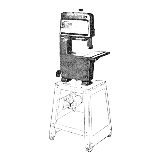
- Page 7 MOUNTING BAND SAW/SANDER ON RECOMMENDED CRAFTSMAN FLOOR BASE 1. Unscrew the four knobs on the front of the band and remove the cover. NOTE: Check bolts which hold feet to the band saw. Make sure they are tight . , . they...
- Page 8 Make sure it extends a little beyond each end of the clamp. gasket will help to prevent sawdust from leaking out. most efficient removal of sawdust, attach Craftsman Home-n-Shop sawdust elbow.
- Page 9 TABLE TRUNNION INSTALLING TABLE NION PiN Remove protective that is applied to the table. Use any ordinary household type grease and spot remover. CAUTION: Never use gasoline, naptha or similar highly volatile solvents. Apply a coat of automobile wax to the table. TABLE LOCK BOLT 1.
- Page 10 assemb|y THREAD CUTTING SCREWS MOTOR PULLEY BELT GUARD MOTOR I NSTA L LAT! ON MOUNTING BELT GUARD 1. Place motor your workbench with shaft facing you. If you are using a double shaft motor, the 5/8" dia. BELT GUARD shaft must be facing you.
- Page 11 s/32 iNCH I SETSCREW WRENC. MOUNTING PULLEY I. Loosen setscrew in motor pulley and place the pulley on the shaft with the hub flush with the end of the shaft, insert motor shaft tighten setscrew with 5/32" setscrew wrench. _J___'_"_ MOTOR FLUSH HERE...
- Page 12 assembly MOUNTING MOTOR 1. Find four 5/16"-18x 1" carriage bolts, flat washers,lock- washersand nuts supplied with base. MOTOR MOUNT BRACKET L--J_ _-_c:_ 2, Insert bolts through holes marked "X" from behind motor mount bracket. 3. Attach motor.., place a flat washer and a Iockwasher BELT GUARD on each holt .
- Page 13 ATTACHING BELT GUARDS 1. Remove the pulley from the band saw, using the 5/32" setscrew wrench loosen the screw. Be careful not to lose the shaft key. Attach the belt guard support with the three screws fur- nished with the guard. NOTE: The support bracket...
- Page 14 assembty LONG POINTED THIS 3. Install three clips on the belt guard 90 ° apart with the long tabs pointing AWAY from round opening. 4. Insert one looped end of belt all the way into guard that it will be below motor pulley.
- Page 15 6. Look down into guard.., pull belt upwards onto motor pulley. 7. Insert belt into open of the second belt guard, and out the round opening, Place belt onto band saw pulley by rotating pulley. 8. Snap the belt guard into position, 9.
- Page 16 assembly GUIDE BAR LOCK KNOB GUIDE 3. Loosen the guide bar lock knob and position the upper guide assembly approximately three inches above table and tighten the knob, UPPER BLADE ..__ UPPER THRUST BEARING 1/8" SETSCREW WR ENCH''_ 4. Loosen the two setscrews which lock the upper blade guides and separate them about 1/8".
- Page 17 UPPER THRUST BEARING THRUST BEARING ADJ. KNOB 5. Loosen the setscrew which locks the upper thrust bear- ing and turn knob until the thrust bearing is all the way back. 1/8" SETSCREW WRENCH BLADE GUIDE LOWER THRUST BEARING SETSCREW 6. Loosen the setscrew which locks the lower thrust...
- Page 18 assembly 7. Carefully uncoil the blade, holding it at arms length. 8. Place the blade over the wheels with the teeth pointing TRACKING downwards. Make sure the blade is between blade ADJUSTMENT guides and is in the center of the rubber tires.
- Page 19 14. Loosen the setscrew which locks the blade guide holder. APPROX. 15. Turn the blade guide adjustment knob, so that the guides 1/32"' BLADE GUIDE move toward the blade. Move them until the "ledge" about 1/32" from the deepest part of the blade teeth.
- Page 20 assembly ON-OFF SW|TCH WARNING: DON'T CONNECT POWER CORD TO ELECTRICAL OUTLET IN YOUR SHOP UNTIL YOU ARE SURE THAT MOTOR ROTATION IS CORRECT. (SEEPAGE 11). The On-Off Switch has a locking feature.TH|S SHOULD PREVENT UNAUTHORIZED AN D POSSIBLY HAZAR- DOUS USE BY CHILDREN AND OTHERS.
- Page 21 3. To turn machine . .. PUSH lever in. Never leave the machine unattended until it has come to a complete stop. 4. To lock switch in OFF position . .. hold switch with one hand . . . REMOVE key with other hand.
- Page 22 getting to know your band saw/sander COVER RETAiNiNG KNOB (4-Used) GUIDE BAR LOCK KNOB /---TENSION ADJUSTING KNOB-_ BLADE TENSION ADJUSTMENT SCALE DIAGRAMS ON-OFF SWITCH "_ BLADE GUARD MOTOR CORD OUTLET GUIDE THRUST BEARING ADJ. KNOB (Lower Knob Not Shown) TILT LOCK HANDLE SAW PULLEY...
- Page 23 9. GUIDE When the upper guides are raised or lowered, they must not deflect the blade sideways. This means that the guide must be parallel to the blade, or square with /_"_"_--__ SCREW table. 1. Remove the blade guard, cover, blade, and the upper guide assembly.
- Page 24 getting to know your band saw/sander 6. Attach the sanding platen to the guide bar with the same screw that held the upper blade guide assembly. Do not tighten the screw at this time. On the smooth side of the sanding belt, you will find a "directional arrow".
- Page 25 Unlike a saw, it is not capable of doing inside cutting. Your Craftsman Band Saw/Sander is not only capable the usual band saw operations, but it can be converted into a sander as well. You can finish...
- Page 26 maintenance WARNING: FOR YOUR OWN SAFETY, TURN :SWITCH "OFF" REMOVE PLUG FROM POWER SOURCE OUTLET BEFORE MAINTAINING LUBRICATING MOTOR OUTLET YOUR BAND SAW. ON-OF F SWITCH TIRES Pitch and sawdust that accumulate on the tires should removed with a stiff brush or scraped off with...
- Page 27 trouble shooting WARNING: FOR YOUR OWN SAFETY, TURN SWITCH "OFF" AND REMOVE PLUG FROM POWER SOURCE OUTLET BEFORE TROUBLE SHOOTING YOUR BAND SAW/SANDER, PROBABLE CAUSE REMEDY TROUBLE Motor will not run. Defective On-Off switch. 1. Replace defective parts before using Defective switch cord.
- Page 28 CRAFTSMAN 12-INCH BAND SAW/SANDER, MODEL 113.24201 SEE FIGURE EXPLODED VIEW...
- Page 29 CRAFTSMAN 12-INCH BAND SAW/SANDER, MODEL 113.24201 All parts illustrated in Figures 1 and 2 and listed under part numbers may be ordered through any Sears Retail Store or Catalog Order House. Order parts by mail from the Catalog Order House that serves the territory in which live.
- Page 30 CRAFTSMAN 12-tNCH BAND SAW/SANDER. MODEL 113.24201 "0 19 14 FIGURE...
- Page 31 CRAFTSMAN 12-INCH BAND SAW/SANDER, MODEL 113.24201 FIGURE 2 PARTS LIST PART PART DESCRIPTION DESCRIPTION 69017 69039 Guide, 8tade Pin, Pointer Pivot STD551050 69045 Guide, Lower Blade Washer, Plain, 1/2 x 1-1/4 × 1/8, STD5510t2 STD551031 Washer, Plain, 17/64 x 1/2 x 1/16 Washer, Plain, 5/16 ×...
- Page 32 Always mention Model Number when requesting service or repair parts for your owners CRAFTSMAN 124NCH BAND SAW/SANDER. manual parts listed herein ordered through SEARS, ROEBUCK CO. or StMPSONS-SEARS LIMITED.