Table of Contents
Advertisement
Operator's Manual
CRAFTSMAN °
i PROFESSI
ONAL
i
12 in. DUAL BEVEL SLIDING COMPOUND
MITER SAW WITH LASER TRAC ®
Model No. 137.212210
C
US
CAUTION:
Before using this Miter Saw,
read this manual and follow
all its Safety Rules and
Operating Instructions
•
Safety Instructions
•
Installation
•
Operation
•
Maintenance
•
Parts List
Customer
Help
Line
For
Technical
Support
1-800-843-1682
Sears
Parts
&
Repair
Center
1-800-488-1222
Sears, Roebuck and Co., Hoffman Estates, IL 60179 USA
Visit our Craftsman website: www.sears.com/craftsman
Part No. 137212210001
Printed in Taiwan
Advertisement
Table of Contents
Troubleshooting

Related Manuals for Craftsman 21221 - 12 in. Sliding Dual Bevel Compound Miter Saw


Summary of Contents for Craftsman 21221 - 12 in. Sliding Dual Bevel Compound Miter Saw
- Page 1 Safety Rules and • Maintenance Operating Instructions • Parts List Sears Parts & Customer Help Line Repair Center Technical Support 1-800-488-1222 1-800-843-1682 Sears, Roebuck and Co., Hoffman Estates, IL 60179 USA Visit our Craftsman website: www.sears.com/craftsman Part No. 137212210001 Printed in Taiwan...
- Page 2 PartsList..................... CRAFTSMAN ONE YEAR FULL WARRANTY If this Craftsman tool fails due to a defect in material or workmanship within one year from the date of purchase, call 1-800-4-MY-HOME® to arrange for free repair (or replacement if repair proves impossible).
-
Page 3: Rotating Table
MOTOR Power Source ....... 120VAC, 60Hz, 15Amp Speed ........... 4200 RPM (No load) Brake ..........Electric Double Insulated ......Yes Motor Arbor Shaft Size ....5/8 in. BLADE SIZE Diameter ........12 in. Arbor size ........1 in.w/a 5/8 in.reducer ROTATING TABLE Diameter ........ - Page 4 WARNING ICONS Your power tool and its Operator's Manual may contain "WARNING ICONS" (a picture symbol intended to alert you to, and/or instruct you how to avoid, a potentially hazardous condition). Understanding and heeding these symbols will help you operate your tool better and safer. Shown below are some of the symbols you may see.
- Page 5 GENERAL SAFETY INSTRUCTIONS DO NOT FORCE THE TOOL. It will BEFORE USING THIS POWER TOOL do the job better and safer at the rate for which it was designed. Safety is a combination of common sense, staying alert and knowing how USE THE RIGHT TOOL.
- Page 6 NOTE: Glasses or goggles not in and any other conditions that may compliance with ANSI Z87.1 could affect its operation. A guard or seriously injure you when they other part that is damaged should break. be properly repaired or replaced. 13.
- Page 7 SPECIFIC SAFETY INSTRUCTIONS 10.USE only blade collars specified for FOR THIS COMPOUND MITER SAW your saw. DO NOT operate the miter saw 11 .NEVER use blades larger in diameter than 12 inches. until it is completely assembled and installed according to these instructions.
- Page 8 21. NEVER cut small pieces. If the workpiece being cut would cause your hand or fingers to be within 8-3/4 in. of the saw blade the workpiece is too small. 22. PROVIDE adequate support to the sides of the saw table for long work pieces.
-
Page 9: Power Supply And Motor Specifications
POWER SUPPLY AND MOTOR way. If the plug does not fit fully in the SPECIFICATIONS outlet, reverse the plug. If it still does The AC motor used in this saw is not fit, contact a qualified electrician to a universal, nonreversible type. install the proper outlet. -
Page 10: Guidelines For Extension Cords
now be started and the cut finished. excessive heat and damp or wet areas. 4. FUSES may "blow" or circuit Use a separate electrical circuit breakers may trip frequently if: for your tools. This circuit must not a. MOTOR is overloaded - be less than a #12 wire with a 20 A overloading can occur if you feed time lag fuse or a #14 wire with a 15... -
Page 11: Recommended Accessories
RECOMMENDED ACCESSORIES without the proper saw blade guard in place. Carbide is a very [_k WARNING hard but brittle material. Care should be taken while mounting, • Use only accessories recommended for this miter using, and storing carbide tipped saw. Follow instructions that blades to prevent accidental damage. - Page 12 Supplied Not supplied Phillips Screwdriver Blade Wrench Adjustable Wrench 6 mm Hex Wrench Slotted Screwdriver l !'-' "-'_,_ i '-:'_,_,_'-' ' -'i '-_, _ Combination Square COMBINATION SQUARE MUST BE TRUE Should not gap or overlap when square is flipped over (see dotted figure). Straight edge or a 3/4 in.
- Page 13 UNPACKING YOUR MITER SAW 3. Separate all parts from the packing material. Check each one with the illustration to make certain all items WARNING are accounted for, before discarding To avoid injury from unexpected any packing material. starting or electrical shock, do not plug the power cord into a source IA WARNING of power during unpacking and...
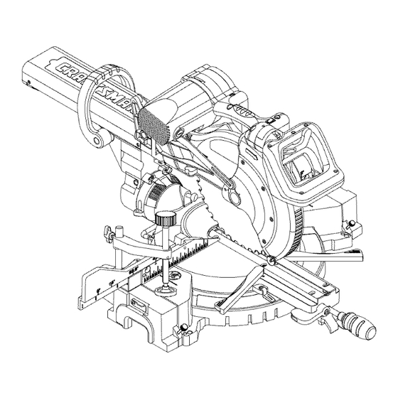
- Page 14 Carry handle Upper blade guard Carry handle Laser ON/OFF switch Handle locking lever Motor Switch handle ON/OFF trigger switch Saw blade Lower blade guard Bevel scale Hold-down clamp Base Sliding fence Miter lock handle Left extension table Bevel lock handle Mounting hole Turntable Left support...
- Page 15 eyes. Eye protection should meet the AMPERAGE (AMPS) - A measure requirements of ANSI Z.87.1 (USA) or of the flow of electric current. Higher CSA Z94.3-M88 (Canada). ratings generally means the tool is suited for heavier use. FACE SHIELD - An impact resistant ARBOR LOCK - Allows the user to shield that helps to protect your face from chips, sparks, small debris.
-
Page 16: Woodworking Terms
POSITIVE STOP LOCKING LEVER - KICKBACK - Sudden and unintended Locks the miter saw at a preset positive movement of the tool or workpiece. It is stop for the desired miter angle. typically caused by binding or pinching of the workpiece SWITCH HANDLE - The switch handle contains the trigger switch and MITER CUT - A miter is a type of joint... -
Page 17: Unlocking The Slide Carriage
ESTIMATED ASSEMBLY TIME: 10~15 Unlocking MINUTES Push down slightly on the switch handle (1). AL WARNING Pull out the hold-down latch (2). To avoid injury, do not connect this 3. Allow the cutting head to rise to the miter saw to the power source until up position. - Page 18 INSTALLING THE DUST THREE POSITION ROTATING COLLECTION ELBOW (FIG. C) HANDLE (FIG. E) The handle of the miter saw has been 1. Install the end of the elbow (1) onto the exhaust port (2). designed to rotate and lock at three NOTE: The elbow can be used different position stops;...
-
Page 19: Power Cord Storage Clips
Fig. F Fig. H I,A WARNING I To avoid injury, disconnect the plug from the power source before performing any adjustments or POWER CORD STORAGE CLIPS repair. (FIG. G) NOTE: Your miter saw was adjusted at For convenience and to prevent the factory. -
Page 20: Mounting The Miter Saw
to the insulation or the wire 1. To remove, loosen and remove the six screws (1) on the table inserts connections resulting in electric shock or fire. (2) with a Phillips screwdriver and remove the inserts. • To avoid injury from flying To install, reposition the table debris, do not allow visitors to inserts, install the six screws and... -
Page 21: Removing Or Installing The Blade
clamp thismounting board toa Fig. L stableworksurface attheworksite. (Fig.K) Fig. K Locate the arbor lock (5) on the motor, below the belt cover. (Fig. M) Press the arbor lock, holding it in firmly while turning the blade clockwise. The arbor lock will then engage and lock the arbor. - Page 22 Place the blade wrench on the NOTE: Pay attention to the pieces arbor bolt. removed, noting their position and direction they face. Wipe the blade Press the arbor lock (5), holding collars clean of any sawdust before it in firmly while turning the blade installing a new blade.
- Page 23 ALIGNING THE LASER BEAM (FIG. • NOTE: All the adjustments for the O, P) operation of this machine have been completed at the factory. WARNING I Due to normal wear and use, For your own safety, never connect some occasional readjustments the plug to power source outlet may be necessary.
- Page 24 the laser element where you can Fig. P position an adjustable wrench for your adjustment. C. Aligning The Laser Beam 1. Loosen only 1/2 turn at a time the four set screws (1). 2. Adjust laser by turning the left side set screws clockwise to shift the laser line to the right.
-
Page 25: Bevel Stop Adjustments
BEVEL STOP ADJUSTMENTS Bevel Scale Indicators (Fig. T) (FIG. S, T, U, V) 1. When the blade is exactly 90o(0 °) to the table, loosen the bevel indicator WARNING screws (1) using a #2 Phillips screwdriver. To avoid injury from unexpected starting or electrical shock, make 2. - Page 26 Fig. U Fig. V 33.9° Left & Right Bevel Adjustment 45 ° Right Bevel Positive Stop (Fig. W) Adjustment (Fig. V) 1. Set the miter angle to zero degree. 1. Set the miter angle to zero degrees. Fully extend both sliding fences. 2.
-
Page 27: Miter Angle Adjustment
2. Loosen the screw (3) that holds the indicator with a screwdriver. 3. Adjust the indicator (2) to the 0 ° o right mark and retighten screw. sitive ustment, ADJUSTING FENCE SQUARENESS rench (FIG. Y) here 1. Loosen the four fence locking bolts NOTE: View from rear of machine (1). - Page 28 handle and rotate the miter table left 4. Turn the lock nut (3) to the right or right to the desired angle. as shown to lock the miter locking 3. Release the positive stop locking mechanism into place. lever and set the miter at the desired angle making sure the lever snaps Fig.
- Page 29 3. Recheck t hebladedepthby moving thecuttinghead frontto back through thefullmotion ofa cutalong thecontrol a rm.If thebladetouches theinside of thecontrol arm,readjust thesetting. Fig. AA SLIDING THE REAR EXTENSION SUPPORT BAR (FIG. BB) WARNING I To avoid possible personal injury or damage to the miter saw due to tipping, do not operate the saw without the Rear Extension Support Bar.
-
Page 30: Troubleshooting Guide
SAFETY INSTRUCTIONS FOR BASIC • Compare the direction of rotation SAW OPERATION arrow on the guard to the direction arrow on the blade. The blade teeth BEFORE USING THE MITER SAW should always point downward at the front of the saw. [_, WARNING •... -
Page 31: Plan Your Work
recommended accessories. assembly, or setup work on the RECOMMENDED ACCESSORIES miter saw while any parts are • Consult the ACCESSORIES moving. and ATTACHMENTS section Avoid accidental starting, of this Operator's Manual for make sure the trigger switch is recommended accessories. Follow disengaged before plugging the the instructions that come with the miter saw into a power outlet. -
Page 32: Inspect Your Workpiece
• Wear non-slip footwear. • Secure work. Use clamps or a vise • Tie back long hair. to help hold the work when it's • Roll long sleeves above the elbow. practical. • Noise levels vary widely. To avoid USE EXTRA CAUTION WITH LARGE possible hearing damage, wear ear OR ODD SHAPED WORKPIECES. -
Page 33: Body And Hand Position
Do not cut metal workpieces • Hold workpiece firmly against the that must be hand held. Clamp fence to prevent movement toward the blade. workpieces securely. Cut non-ferrous metals only if you • With the power switch OFF, are under the supervision of an bring the saw blade down to the experienced person and the dust workpiece to see the cutting path of... - Page 34 TO TURN THE SAW ON (FIG. DD) The right side sliding fence must Depress the trigger switch (1) to turn be removed when making any on the miter saw started. right bevel angle cuts greater than 350 in combination with NOTE: Make the ON/OFF switch any right hand miter angle.
- Page 35 REMOVING OR INSTALLING THE Fig. GG RIGHT SLIDING FENCE Removing (Fig. FF) Unlock the fence cam-locking lever by pushing it out toward the rear of the machine. Lift up on the sliding fence to remove it from the saw. Installing Place the sliding fence onto the miter saw fence aligning the nut (1) WARNING...
- Page 36 fence must also be removed Once the desired miter angle is achieved, press down on the quick whenever a 45 ° bevel angle cam miter table lock to secure the is desired with a miter angle table into position. greater than 22.5 °. If the miter angle desired is NOT one of the ten positive stops noted Tilt the cutting head to the desired...
- Page 37 33.9 ° BEVEL DETENT PIN FOR Fig. KK CROWN MOLDINGS (FIG. JJ) NOTE: A bevel detent pin is incorporated into this machine for quick bevel adjustments when the desired bevel angle is 33.9 °. Push the bevel detent stop pin (1) in toward the front of the machine.
- Page 38 Fig. LL Set both the desired bevel angle and/or the miter angle and lock into position. If bevel cutting, set both the left and right sliding fences (2) to their proper location. Use a hold down clamp to secure the workpiece. Grasp the switch handle (3) and pull the carriage (4) forward until the center of the saw blade is over...
- Page 39 CUTTING BOWED MATERIAL (FIG. While holding the upper arm in position, turn the stop knob (2) until it touches the stop plate (1). WARNING Cut two parallel grooves as shown below. To avoid injury from materials being thrown, always unplug the saw to Fig.
- Page 40 Fig. PP CHANGING THE BELT (FIG. RR, SS) • Unplug your saw. Loosen the bolts (1) and remove the belt cover. Turn the screw (2) anti-clockwise with a hex wrench to move the motor to forward. Remove and replace the belt. Turn the screw (2) clockwise with a hex wrench to move the motor to rearward.
- Page 41 CUTTING BASE MOLDING (FIG. TT) angles that, when added together, Base moldings and many other equal exactly 90 °. moldings can be cut on a compound Most crown molding has a top rear miter saw. The setup of the saw angle (the section that fits flat against depends on molding characteristics the ceiling) of 52°and a bottom rear...
-
Page 42: Type Of Cut
Bevel/Miter Settings BEVEL MITER TYPE OF CUT SETTING SETTING Inside corner-Left side 33.9 ° 31.6 o Right 1. Position top of molding against fence. 2. Miter table set at RIGHT 31.6 ° . 3. LEFT side is finished piece. Inside corner-Right side 33.9 °... -
Page 43: Crown Molding Chart
CROWN MOLDING CHART Compound Miter saw Miter and bevel Angle settings Wall to Crown Molding Angle 82/38 ° Crown Molding 45/45 ° Crown Molding 52/38 ° C_wn Molding 45/45 ° C_wn Molding Angle Miter Bevel Miter Bevet Angle Miter Bevel Miter Bevel Between... - Page 44 MAINTENANCE the carbon part fits into. Tighten the cap snugly, but do not overtighten. DANGER NOTE: To reinstall the same brushes, To avoid injury, never put lubricants on the blade while it is spinning. first make sure the brushes go back in the way they came out.
- Page 45 SAWDUST Periodically, sawdust will accumulate under the work table and base. This could cause difficulty in the movement of the worktable when setting up a miter cut. Frequently blow out or vacuum up the sawdust. WARNING J If blowing sawdust, wear proper eye protection to keep debris from entering eyes.
-
Page 46: Troubleshooting
WARNING To avoid injury from accidental starting, always turn switch OFF and unplug the tool before moving, replacing the blade or making adjustments, TROUBLESHOOTING GUIDE - MOTOR SUGGESTED CORRECTIVE PROBLEM PROBLEM CAUSE ACTION Brake does Motor brushes not sealed Inspect/clean/replace brushes. -
Page 47: Eye Protection
TROUBLESHOOTING GUIDE - SAW OPERATION SUGGESTED CORRECTIVE PROBLEM PROBLEM CAUSE ACTION Blade hits 1. Misalignment. See ADJUSTMENT -Setting table. Cutting Depth section. Angle of cut 1. Miter table unlocked. See OPERATION - Miter Angle not accurate. 2. Sawdust under table. Adjustment section. - Page 48 12 in. COMPOUND MITER SAW MODEL NO. 137.212210 _ik WARNING When servicing use only CRAFTSMAN replacement parts. Use of any other parts many create a HAZARD or cause product damage. Any attempt to repair or replace electrical parts on this Miter Saw may create a HAZARD unless repair is done by a qualified service technician.
- Page 49 262U 145V 2QU3 246_ I1"1 I" 2LK2 ".4 OI,MH 2P4_ 2CG'['4 _i 43B z...
- Page 50 12 in. COMPOUND MITER SAW MODEL NO. 137.212210 PARTS LIST FOR SAW SCHEMATIC I.D. Description Size I.D. Description Size 0831 SHAFT SLEEVE OKR4 LOCK NUT M8_1.25 T=8 2750 CAUTION LABEL OKSP STRAIN RELIEF 2841 CENTER SHAFT 25XZ ARM-MITER OCEZ PLUNGER HANDLE 25YG NEEDLE POINTER OD7Z...
- Page 51 .N" • 2SY9 _?HE 26HX 27J9 ", 083I__ OH9W 26PU 26P7 \OJBO 262V /27BC 25YK / 0Jppz 0KMYa OJXO / I'll 26NS ENGV 25YG /...
- Page 52 12 in. COMPOUND MITER SAW MODEL NO. 137.212210 PARTS LIST FOR SAW SCHEMATIC I.D. Description Size Qty I.D. Description Size 2258 SPECIAL BOLT 25V3 KNOB 2754 WARNING LABEL 25XX BASE 082J CUSHION 25Y0 ASSIST-FENCE 082L BOLT 25Y2 EXTENSION WING 0CDD FOOT 25Y3 ASSIST-FENCE...
- Page 53 .N" • "u 27KP +_/+'+L+ io+_ I'll \25XX...
- Page 54 12 in. COMPOUND MITER SAW MODEL NO. 137.212210 PARTS LIST FOR MOTOR Description Size I.D. OJB8 WAVE WASHER OJX3 HEX. SOC. SETSCREW M5"0.8-8 OJXC HEX. SOC. SETSCREW M6"1.0-20 0K38 CR. RE. PAN HD. SCREW & WASHER M5"0.8-8 OK3T CR. RE. PAN HD. SCREW & WASHER M5"0.8-25 OK3Y CR.
- Page 56 Your Home For expert troubleshooting and home solutions advice: manage home www.managemyhome.com For repair - in your home - of all major brand appliances, lawn and garden equipment, or heating and cooling systems, no matter who made it, no matter who sold it! For the replacement parts, accessories and owner's manuals that you need to do-it-yourself.
- Page 57 Safety Rules and • Maintenance Operating Instructions • Parts List Sears Parts & Customer Help Line Repair Center Technical Support 1-800-488-1222 1-800-843-1682 Sears, Roebuck and Co., Hoffman Estates, IL 60179 USA Visit our Craftsman website: www.sears.com/craftsman Part No. 137212210001 Printed in Taiwan...
- Page 58 PartsList..................... CRAFTSMAN ONE YEAR FULL WARRANTY If this Craftsman tool fails due to a defect in material or workmanship within one year from the date of purchase, call 1-800-4-MY-HOME® to arrange for free repair (or replacement if repair proves impossible).
-
Page 59: Rotating Table
MOTOR Power Source ....... 120VAC, 60Hz, 15Amp Speed ........... 4200 RPM (No load) Brake ..........Electric Double Insulated ......Yes Motor Arbor Shaft Size ....5/8 in. BLADE SIZE Diameter ........12 in. Arbor size ........1 in.w/a 5/8 in.reducer ROTATING TABLE Diameter ........ - Page 60 WARNING ICONS Your power tool and its Operator's Manual may contain "WARNING ICONS" (a picture symbol intended to alert you to, and/or instruct you how to avoid, a potentially hazardous condition). Understanding and heeding these symbols will help you operate your tool better and safer. Shown below are some of the symbols you may see.
- Page 61 GENERAL SAFETY INSTRUCTIONS DO NOT FORCE THE TOOL. It will BEFORE USING THIS POWER TOOL do the job better and safer at the rate for which it was designed. Safety is a combination of common sense, staying alert and knowing how USE THE RIGHT TOOL.
- Page 62 NOTE: Glasses or goggles not in and any other conditions that may compliance with ANSI Z87.1 could affect its operation. A guard or seriously injure you when they other part that is damaged should break. be properly repaired or replaced. 13.
- Page 63 SPECIFIC SAFETY INSTRUCTIONS 10.USE only blade collars specified for FOR THIS COMPOUND MITER SAW your saw. DO NOT operate the miter saw 11 .NEVER use blades larger in diameter than 12 inches. until it is completely assembled and installed according to these instructions.
- Page 64 21. NEVER cut small pieces. If the workpiece being cut would cause your hand or fingers to be within 8-3/4 in. of the saw blade the workpiece is too small. 22. PROVIDE adequate support to the sides of the saw table for long work pieces.
-
Page 65: Power Supply And Motor Specifications
POWER SUPPLY AND MOTOR way. If the plug does not fit fully in the SPECIFICATIONS outlet, reverse the plug. If it still does The AC motor used in this saw is not fit, contact a qualified electrician to a universal, nonreversible type. install the proper outlet. -
Page 66: Guidelines For Extension Cords
now be started and the cut finished. excessive heat and damp or wet areas. 4. FUSES may "blow" or circuit Use a separate electrical circuit breakers may trip frequently if: for your tools. This circuit must not a. MOTOR is overloaded - be less than a #12 wire with a 20 A overloading can occur if you feed time lag fuse or a #14 wire with a 15... -
Page 67: Recommended Accessories
RECOMMENDED ACCESSORIES without the proper saw blade guard in place. Carbide is a very [_k WARNING hard but brittle material. Care should be taken while mounting, • Use only accessories recommended for this miter using, and storing carbide tipped saw. Follow instructions that blades to prevent accidental damage. - Page 68 Supplied Not supplied Phillips Screwdriver Blade Wrench Adjustable Wrench 6 mm Hex Wrench Slotted Screwdriver l !'-' "-'_,_ i '-:'_,_,_'-' ' -'i '-_, _ Combination Square COMBINATION SQUARE MUST BE TRUE Should not gap or overlap when square is flipped over (see dotted figure). Straight edge or a 3/4 in.
- Page 69 UNPACKING YOUR MITER SAW 3. Separate all parts from the packing material. Check each one with the illustration to make certain all items WARNING are accounted for, before discarding To avoid injury from unexpected any packing material. starting or electrical shock, do not plug the power cord into a source IA WARNING of power during unpacking and...
- Page 70 Carry handle Upper blade guard Carry handle Laser ON/OFF switch Handle locking lever Motor Switch handle ON/OFF trigger switch Saw blade Lower blade guard Bevel scale Hold-down clamp Base Sliding fence Miter lock handle Left extension table Bevel lock handle Mounting hole Turntable Left support...
- Page 71 eyes. Eye protection should meet the AMPERAGE (AMPS) - A measure requirements of ANSI Z.87.1 (USA) or of the flow of electric current. Higher CSA Z94.3-M88 (Canada). ratings generally means the tool is suited for heavier use. FACE SHIELD - An impact resistant ARBOR LOCK - Allows the user to shield that helps to protect your face from chips, sparks, small debris.
-
Page 72: Woodworking Terms
POSITIVE STOP LOCKING LEVER - KICKBACK - Sudden and unintended Locks the miter saw at a preset positive movement of the tool or workpiece. It is stop for the desired miter angle. typically caused by binding or pinching of the workpiece SWITCH HANDLE - The switch handle contains the trigger switch and MITER CUT - A miter is a type of joint... -
Page 73: Unlocking The Slide Carriage
ESTIMATED ASSEMBLY TIME: 10~15 Unlocking MINUTES Push down slightly on the switch handle (1). AL WARNING Pull out the hold-down latch (2). To avoid injury, do not connect this 3. Allow the cutting head to rise to the miter saw to the power source until up position. - Page 74 INSTALLING THE DUST THREE POSITION ROTATING COLLECTION ELBOW (FIG. C) HANDLE (FIG. E) The handle of the miter saw has been 1. Install the end of the elbow (1) onto the exhaust port (2). designed to rotate and lock at three NOTE: The elbow can be used different position stops;...
-
Page 75: Power Cord Storage Clips
Fig. F Fig. H I,A WARNING I To avoid injury, disconnect the plug from the power source before performing any adjustments or POWER CORD STORAGE CLIPS repair. (FIG. G) NOTE: Your miter saw was adjusted at For convenience and to prevent the factory. -
Page 76: Mounting The Miter Saw
to the insulation or the wire 1. To remove, loosen and remove the six screws (1) on the table inserts connections resulting in electric shock or fire. (2) with a Phillips screwdriver and remove the inserts. • To avoid injury from flying To install, reposition the table debris, do not allow visitors to inserts, install the six screws and... -
Page 77: Removing Or Installing The Blade
clamp thismounting board toa Fig. L stableworksurface attheworksite. (Fig.K) Fig. K Locate the arbor lock (5) on the motor, below the belt cover. (Fig. M) Press the arbor lock, holding it in firmly while turning the blade clockwise. The arbor lock will then engage and lock the arbor. - Page 78 Place the blade wrench on the NOTE: Pay attention to the pieces arbor bolt. removed, noting their position and direction they face. Wipe the blade Press the arbor lock (5), holding collars clean of any sawdust before it in firmly while turning the blade installing a new blade.
- Page 79 ALIGNING THE LASER BEAM (FIG. • NOTE: All the adjustments for the O, P) operation of this machine have been completed at the factory. WARNING I Due to normal wear and use, For your own safety, never connect some occasional readjustments the plug to power source outlet may be necessary.
- Page 80 the laser element where you can Fig. P position an adjustable wrench for your adjustment. C. Aligning The Laser Beam 1. Loosen only 1/2 turn at a time the four set screws (1). 2. Adjust laser by turning the left side set screws clockwise to shift the laser line to the right.
-
Page 81: Bevel Stop Adjustments
BEVEL STOP ADJUSTMENTS Bevel Scale Indicators (Fig. T) (FIG. S, T, U, V) 1. When the blade is exactly 90o(0 °) to the table, loosen the bevel indicator WARNING screws (1) using a #2 Phillips screwdriver. To avoid injury from unexpected starting or electrical shock, make 2. - Page 82 Fig. U Fig. V 33.9° Left & Right Bevel Adjustment 45 ° Right Bevel Positive Stop (Fig. W) Adjustment (Fig. V) 1. Set the miter angle to zero degree. 1. Set the miter angle to zero degrees. Fully extend both sliding fences. 2.
-
Page 83: Miter Angle Adjustment
2. Loosen the screw (3) that holds the indicator with a screwdriver. 3. Adjust the indicator (2) to the 0 ° o right mark and retighten screw. sitive ustment, ADJUSTING FENCE SQUARENESS rench (FIG. Y) here 1. Loosen the four fence locking bolts NOTE: View from rear of machine (1). - Page 84 handle and rotate the miter table left 4. Turn the lock nut (3) to the right or right to the desired angle. as shown to lock the miter locking 3. Release the positive stop locking mechanism into place. lever and set the miter at the desired angle making sure the lever snaps Fig.
- Page 85 3. Recheck t hebladedepthby moving thecuttinghead frontto back through thefullmotion ofa cutalong thecontrol a rm.If thebladetouches theinside of thecontrol arm,readjust thesetting. Fig. AA SLIDING THE REAR EXTENSION SUPPORT BAR (FIG. BB) WARNING I To avoid possible personal injury or damage to the miter saw due to tipping, do not operate the saw without the Rear Extension Support Bar.
-
Page 86: Troubleshooting Guide
SAFETY INSTRUCTIONS FOR BASIC • Compare the direction of rotation SAW OPERATION arrow on the guard to the direction arrow on the blade. The blade teeth BEFORE USING THE MITER SAW should always point downward at the front of the saw. [_, WARNING •... -
Page 87: Plan Your Work
recommended accessories. assembly, or setup work on the RECOMMENDED ACCESSORIES miter saw while any parts are • Consult the ACCESSORIES moving. and ATTACHMENTS section Avoid accidental starting, of this Operator's Manual for make sure the trigger switch is recommended accessories. Follow disengaged before plugging the the instructions that come with the miter saw into a power outlet. -
Page 88: Inspect Your Workpiece
• Wear non-slip footwear. • Secure work. Use clamps or a vise • Tie back long hair. to help hold the work when it's • Roll long sleeves above the elbow. practical. • Noise levels vary widely. To avoid USE EXTRA CAUTION WITH LARGE possible hearing damage, wear ear OR ODD SHAPED WORKPIECES. -
Page 89: Body And Hand Position
Do not cut metal workpieces • Hold workpiece firmly against the that must be hand held. Clamp fence to prevent movement toward the blade. workpieces securely. Cut non-ferrous metals only if you • With the power switch OFF, are under the supervision of an bring the saw blade down to the experienced person and the dust workpiece to see the cutting path of... - Page 90 TO TURN THE SAW ON (FIG. DD) The right side sliding fence must Depress the trigger switch (1) to turn be removed when making any on the miter saw started. right bevel angle cuts greater than 350 in combination with NOTE: Make the ON/OFF switch any right hand miter angle.
- Page 91 REMOVING OR INSTALLING THE Fig. GG RIGHT SLIDING FENCE Removing (Fig. FF) Unlock the fence cam-locking lever by pushing it out toward the rear of the machine. Lift up on the sliding fence to remove it from the saw. Installing Place the sliding fence onto the miter saw fence aligning the nut (1) WARNING...
- Page 92 fence must also be removed Once the desired miter angle is achieved, press down on the quick whenever a 45 ° bevel angle cam miter table lock to secure the is desired with a miter angle table into position. greater than 22.5 °. If the miter angle desired is NOT one of the ten positive stops noted Tilt the cutting head to the desired...
- Page 93 33.9 ° BEVEL DETENT PIN FOR Fig. KK CROWN MOLDINGS (FIG. JJ) NOTE: A bevel detent pin is incorporated into this machine for quick bevel adjustments when the desired bevel angle is 33.9 °. Push the bevel detent stop pin (1) in toward the front of the machine.
- Page 94 Fig. LL Set both the desired bevel angle and/or the miter angle and lock into position. If bevel cutting, set both the left and right sliding fences (2) to their proper location. Use a hold down clamp to secure the workpiece. Grasp the switch handle (3) and pull the carriage (4) forward until the center of the saw blade is over...
- Page 95 CUTTING BOWED MATERIAL (FIG. While holding the upper arm in position, turn the stop knob (2) until it touches the stop plate (1). WARNING Cut two parallel grooves as shown below. To avoid injury from materials being thrown, always unplug the saw to Fig.
- Page 96 Fig. PP CHANGING THE BELT (FIG. RR, SS) • Unplug your saw. Loosen the bolts (1) and remove the belt cover. Turn the screw (2) anti-clockwise with a hex wrench to move the motor to forward. Remove and replace the belt. Turn the screw (2) clockwise with a hex wrench to move the motor to rearward.
- Page 97 CUTTING BASE MOLDING (FIG. TT) angles that, when added together, Base moldings and many other equal exactly 90 °. moldings can be cut on a compound Most crown molding has a top rear miter saw. The setup of the saw angle (the section that fits flat against depends on molding characteristics the ceiling) of 52°and a bottom rear...
-
Page 98: Type Of Cut
Bevel/Miter Settings BEVEL MITER TYPE OF CUT SETTING SETTING Inside corner-Left side 33.9 ° 31.6 o Right 1. Position top of molding against fence. 2. Miter table set at RIGHT 31.6 ° . 3. LEFT side is finished piece. Inside corner-Right side 33.9 °... -
Page 99: Crown Molding Chart
CROWN MOLDING CHART Compound Miter saw Miter and bevel Angle settings Wall to Crown Molding Angle 82/38 ° Crown Molding 45/45 ° Crown Molding 52/38 ° C_wn Molding 45/45 ° C_wn Molding Angle Miter Bevel Miter Bevet Angle Miter Bevel Miter Bevel Between... - Page 100 MAINTENANCE the carbon part fits into. Tighten the cap snugly, but do not overtighten. DANGER NOTE: To reinstall the same brushes, To avoid injury, never put lubricants on the blade while it is spinning. first make sure the brushes go back in the way they came out.
- Page 101 SAWDUST Periodically, sawdust will accumulate under the work table and base. This could cause difficulty in the movement of the worktable when setting up a miter cut. Frequently blow out or vacuum up the sawdust. WARNING J If blowing sawdust, wear proper eye protection to keep debris from entering eyes.
-
Page 102: Troubleshooting
WARNING To avoid injury from accidental starting, always turn switch OFF and unplug the tool before moving, replacing the blade or making adjustments, TROUBLESHOOTING GUIDE - MOTOR SUGGESTED CORRECTIVE PROBLEM PROBLEM CAUSE ACTION Brake does Motor brushes not sealed Inspect/clean/replace brushes. -
Page 103: Eye Protection
TROUBLESHOOTING GUIDE - SAW OPERATION SUGGESTED CORRECTIVE PROBLEM PROBLEM CAUSE ACTION Blade hits 1. Misalignment. See ADJUSTMENT -Setting table. Cutting Depth section. Angle of cut 1. Miter table unlocked. See OPERATION - Miter Angle not accurate. 2. Sawdust under table. Adjustment section. - Page 104 12 in. COMPOUND MITER SAW MODEL NO. 137.212210 _ik WARNING When servicing use only CRAFTSMAN replacement parts. Use of any other parts many create a HAZARD or cause product damage. Any attempt to repair or replace electrical parts on this Miter Saw may create a HAZARD unless repair is done by a qualified service technician.
- Page 105 262U 145V 2QU3 246_ I1"1 I" 2LK2 ".4 OI,MH 2P4_ 2CG'['4 _i 43B z...
- Page 106 12 in. COMPOUND MITER SAW MODEL NO. 137.212210 PARTS LIST FOR SAW SCHEMATIC I.D. Description Size I.D. Description Size 0831 SHAFT SLEEVE OKR4 LOCK NUT M8_1.25 T=8 2750 CAUTION LABEL OKSP STRAIN RELIEF 2841 CENTER SHAFT 25XZ ARM-MITER OCEZ PLUNGER HANDLE 25YG NEEDLE POINTER OD7Z...
- Page 107 .N" • 2SY9 _?HE 26HX 27J9 ", 083I__ OH9W 26PU 26P7 \OJBO 262V /27BC 25YK / 0Jppz 0KMYa OJXO / I'll 26NS ENGV 25YG /...
- Page 108 12 in. COMPOUND MITER SAW MODEL NO. 137.212210 PARTS LIST FOR SAW SCHEMATIC I.D. Description Size Qty I.D. Description Size 2258 SPECIAL BOLT 25V3 KNOB 2754 WARNING LABEL 25XX BASE 082J CUSHION 25Y0 ASSIST-FENCE 082L BOLT 25Y2 EXTENSION WING 0CDD FOOT 25Y3 ASSIST-FENCE...
- Page 109 .N" • "u 27KP +_/+'+L+ io+_ I'll \25XX...
- Page 110 12 in. COMPOUND MITER SAW MODEL NO. 137.212210 PARTS LIST FOR MOTOR Description Size I.D. OJB8 WAVE WASHER OJX3 HEX. SOC. SETSCREW M5"0.8-8 OJXC HEX. SOC. SETSCREW M6"1.0-20 0K38 CR. RE. PAN HD. SCREW & WASHER M5"0.8-8 OK3T CR. RE. PAN HD. SCREW & WASHER M5"0.8-25 OK3Y CR.
- Page 112 Your Home For expert troubleshooting and home solutions advice: manage home www.managemyhome.com For repair - in your home - of all major brand appliances, lawn and garden equipment, or heating and cooling systems, no matter who made it, no matter who sold it! For the replacement parts, accessories and owner's manuals that you need to do-it-yourself.
- Page 113 Safety Rules and • Maintenance Operating Instructions • Parts List Sears Parts & Customer Help Line Repair Center Technical Support 1-800-488-1222 1-800-843-1682 Sears, Roebuck and Co., Hoffman Estates, IL 60179 USA Visit our Craftsman website: www.sears.com/craftsman Part No. 137212210001 Printed in Taiwan...
- Page 114 PartsList..................... CRAFTSMAN ONE YEAR FULL WARRANTY If this Craftsman tool fails due to a defect in material or workmanship within one year from the date of purchase, call 1-800-4-MY-HOME® to arrange for free repair (or replacement if repair proves impossible).
-
Page 115: Rotating Table
MOTOR Power Source ....... 120VAC, 60Hz, 15Amp Speed ........... 4200 RPM (No load) Brake ..........Electric Double Insulated ......Yes Motor Arbor Shaft Size ....5/8 in. BLADE SIZE Diameter ........12 in. Arbor size ........1 in.w/a 5/8 in.reducer ROTATING TABLE Diameter ........ - Page 116 WARNING ICONS Your power tool and its Operator's Manual may contain "WARNING ICONS" (a picture symbol intended to alert you to, and/or instruct you how to avoid, a potentially hazardous condition). Understanding and heeding these symbols will help you operate your tool better and safer. Shown below are some of the symbols you may see.
- Page 117 GENERAL SAFETY INSTRUCTIONS DO NOT FORCE THE TOOL. It will BEFORE USING THIS POWER TOOL do the job better and safer at the rate for which it was designed. Safety is a combination of common sense, staying alert and knowing how USE THE RIGHT TOOL.
- Page 118 NOTE: Glasses or goggles not in and any other conditions that may compliance with ANSI Z87.1 could affect its operation. A guard or seriously injure you when they other part that is damaged should break. be properly repaired or replaced. 13.
- Page 119 SPECIFIC SAFETY INSTRUCTIONS 10.USE only blade collars specified for FOR THIS COMPOUND MITER SAW your saw. DO NOT operate the miter saw 11 .NEVER use blades larger in diameter than 12 inches. until it is completely assembled and installed according to these instructions.
- Page 120 21. NEVER cut small pieces. If the workpiece being cut would cause your hand or fingers to be within 8-3/4 in. of the saw blade the workpiece is too small. 22. PROVIDE adequate support to the sides of the saw table for long work pieces.
-
Page 121: Power Supply And Motor Specifications
POWER SUPPLY AND MOTOR way. If the plug does not fit fully in the SPECIFICATIONS outlet, reverse the plug. If it still does The AC motor used in this saw is not fit, contact a qualified electrician to a universal, nonreversible type. install the proper outlet. -
Page 122: Guidelines For Extension Cords
now be started and the cut finished. excessive heat and damp or wet areas. 4. FUSES may "blow" or circuit Use a separate electrical circuit breakers may trip frequently if: for your tools. This circuit must not a. MOTOR is overloaded - be less than a #12 wire with a 20 A overloading can occur if you feed time lag fuse or a #14 wire with a 15... -
Page 123: Recommended Accessories
RECOMMENDED ACCESSORIES without the proper saw blade guard in place. Carbide is a very [_k WARNING hard but brittle material. Care should be taken while mounting, • Use only accessories recommended for this miter using, and storing carbide tipped saw. Follow instructions that blades to prevent accidental damage. - Page 124 Supplied Not supplied Phillips Screwdriver Blade Wrench Adjustable Wrench 6 mm Hex Wrench Slotted Screwdriver l !'-' "-'_,_ i '-:'_,_,_'-' ' -'i '-_, _ Combination Square COMBINATION SQUARE MUST BE TRUE Should not gap or overlap when square is flipped over (see dotted figure). Straight edge or a 3/4 in.
- Page 125 UNPACKING YOUR MITER SAW 3. Separate all parts from the packing material. Check each one with the illustration to make certain all items WARNING are accounted for, before discarding To avoid injury from unexpected any packing material. starting or electrical shock, do not plug the power cord into a source IA WARNING of power during unpacking and...
- Page 126 Carry handle Upper blade guard Carry handle Laser ON/OFF switch Handle locking lever Motor Switch handle ON/OFF trigger switch Saw blade Lower blade guard Bevel scale Hold-down clamp Base Sliding fence Miter lock handle Left extension table Bevel lock handle Mounting hole Turntable Left support...
- Page 127 eyes. Eye protection should meet the AMPERAGE (AMPS) - A measure requirements of ANSI Z.87.1 (USA) or of the flow of electric current. Higher CSA Z94.3-M88 (Canada). ratings generally means the tool is suited for heavier use. FACE SHIELD - An impact resistant ARBOR LOCK - Allows the user to shield that helps to protect your face from chips, sparks, small debris.
-
Page 128: Woodworking Terms
POSITIVE STOP LOCKING LEVER - KICKBACK - Sudden and unintended Locks the miter saw at a preset positive movement of the tool or workpiece. It is stop for the desired miter angle. typically caused by binding or pinching of the workpiece SWITCH HANDLE - The switch handle contains the trigger switch and MITER CUT - A miter is a type of joint... -
Page 129: Unlocking The Slide Carriage
ESTIMATED ASSEMBLY TIME: 10~15 Unlocking MINUTES Push down slightly on the switch handle (1). AL WARNING Pull out the hold-down latch (2). To avoid injury, do not connect this 3. Allow the cutting head to rise to the miter saw to the power source until up position. - Page 130 INSTALLING THE DUST THREE POSITION ROTATING COLLECTION ELBOW (FIG. C) HANDLE (FIG. E) The handle of the miter saw has been 1. Install the end of the elbow (1) onto the exhaust port (2). designed to rotate and lock at three NOTE: The elbow can be used different position stops;...
-
Page 131: Power Cord Storage Clips
Fig. F Fig. H I,A WARNING I To avoid injury, disconnect the plug from the power source before performing any adjustments or POWER CORD STORAGE CLIPS repair. (FIG. G) NOTE: Your miter saw was adjusted at For convenience and to prevent the factory. -
Page 132: Mounting The Miter Saw
to the insulation or the wire 1. To remove, loosen and remove the six screws (1) on the table inserts connections resulting in electric shock or fire. (2) with a Phillips screwdriver and remove the inserts. • To avoid injury from flying To install, reposition the table debris, do not allow visitors to inserts, install the six screws and... -
Page 133: Removing Or Installing The Blade
clamp thismounting board toa Fig. L stableworksurface attheworksite. (Fig.K) Fig. K Locate the arbor lock (5) on the motor, below the belt cover. (Fig. M) Press the arbor lock, holding it in firmly while turning the blade clockwise. The arbor lock will then engage and lock the arbor. - Page 134 Place the blade wrench on the NOTE: Pay attention to the pieces arbor bolt. removed, noting their position and direction they face. Wipe the blade Press the arbor lock (5), holding collars clean of any sawdust before it in firmly while turning the blade installing a new blade.
- Page 135 ALIGNING THE LASER BEAM (FIG. • NOTE: All the adjustments for the O, P) operation of this machine have been completed at the factory. WARNING I Due to normal wear and use, For your own safety, never connect some occasional readjustments the plug to power source outlet may be necessary.
- Page 136 the laser element where you can Fig. P position an adjustable wrench for your adjustment. C. Aligning The Laser Beam 1. Loosen only 1/2 turn at a time the four set screws (1). 2. Adjust laser by turning the left side set screws clockwise to shift the laser line to the right.
-
Page 137: Bevel Stop Adjustments
BEVEL STOP ADJUSTMENTS Bevel Scale Indicators (Fig. T) (FIG. S, T, U, V) 1. When the blade is exactly 90o(0 °) to the table, loosen the bevel indicator WARNING screws (1) using a #2 Phillips screwdriver. To avoid injury from unexpected starting or electrical shock, make 2. - Page 138 Fig. U Fig. V 33.9° Left & Right Bevel Adjustment 45 ° Right Bevel Positive Stop (Fig. W) Adjustment (Fig. V) 1. Set the miter angle to zero degree. 1. Set the miter angle to zero degrees. Fully extend both sliding fences. 2.
-
Page 139: Miter Angle Adjustment
2. Loosen the screw (3) that holds the indicator with a screwdriver. 3. Adjust the indicator (2) to the 0 ° o right mark and retighten screw. sitive ustment, ADJUSTING FENCE SQUARENESS rench (FIG. Y) here 1. Loosen the four fence locking bolts NOTE: View from rear of machine (1). - Page 140 handle and rotate the miter table left 4. Turn the lock nut (3) to the right or right to the desired angle. as shown to lock the miter locking 3. Release the positive stop locking mechanism into place. lever and set the miter at the desired angle making sure the lever snaps Fig.
- Page 141 3. Recheck t hebladedepthby moving thecuttinghead frontto back through thefullmotion ofa cutalong thecontrol a rm.If thebladetouches theinside of thecontrol arm,readjust thesetting. Fig. AA SLIDING THE REAR EXTENSION SUPPORT BAR (FIG. BB) WARNING I To avoid possible personal injury or damage to the miter saw due to tipping, do not operate the saw without the Rear Extension Support Bar.
-
Page 142: Troubleshooting Guide
SAFETY INSTRUCTIONS FOR BASIC • Compare the direction of rotation SAW OPERATION arrow on the guard to the direction arrow on the blade. The blade teeth BEFORE USING THE MITER SAW should always point downward at the front of the saw. [_, WARNING •... -
Page 143: Plan Your Work
recommended accessories. assembly, or setup work on the RECOMMENDED ACCESSORIES miter saw while any parts are • Consult the ACCESSORIES moving. and ATTACHMENTS section Avoid accidental starting, of this Operator's Manual for make sure the trigger switch is recommended accessories. Follow disengaged before plugging the the instructions that come with the miter saw into a power outlet. -
Page 144: Inspect Your Workpiece
• Wear non-slip footwear. • Secure work. Use clamps or a vise • Tie back long hair. to help hold the work when it's • Roll long sleeves above the elbow. practical. • Noise levels vary widely. To avoid USE EXTRA CAUTION WITH LARGE possible hearing damage, wear ear OR ODD SHAPED WORKPIECES. -
Page 145: Body And Hand Position
Do not cut metal workpieces • Hold workpiece firmly against the that must be hand held. Clamp fence to prevent movement toward the blade. workpieces securely. Cut non-ferrous metals only if you • With the power switch OFF, are under the supervision of an bring the saw blade down to the experienced person and the dust workpiece to see the cutting path of... - Page 146 TO TURN THE SAW ON (FIG. DD) The right side sliding fence must Depress the trigger switch (1) to turn be removed when making any on the miter saw started. right bevel angle cuts greater than 350 in combination with NOTE: Make the ON/OFF switch any right hand miter angle.
- Page 147 REMOVING OR INSTALLING THE Fig. GG RIGHT SLIDING FENCE Removing (Fig. FF) Unlock the fence cam-locking lever by pushing it out toward the rear of the machine. Lift up on the sliding fence to remove it from the saw. Installing Place the sliding fence onto the miter saw fence aligning the nut (1) WARNING...
- Page 148 fence must also be removed Once the desired miter angle is achieved, press down on the quick whenever a 45 ° bevel angle cam miter table lock to secure the is desired with a miter angle table into position. greater than 22.5 °. If the miter angle desired is NOT one of the ten positive stops noted Tilt the cutting head to the desired...
- Page 149 33.9 ° BEVEL DETENT PIN FOR Fig. KK CROWN MOLDINGS (FIG. JJ) NOTE: A bevel detent pin is incorporated into this machine for quick bevel adjustments when the desired bevel angle is 33.9 °. Push the bevel detent stop pin (1) in toward the front of the machine.
- Page 150 Fig. LL Set both the desired bevel angle and/or the miter angle and lock into position. If bevel cutting, set both the left and right sliding fences (2) to their proper location. Use a hold down clamp to secure the workpiece. Grasp the switch handle (3) and pull the carriage (4) forward until the center of the saw blade is over...
- Page 151 CUTTING BOWED MATERIAL (FIG. While holding the upper arm in position, turn the stop knob (2) until it touches the stop plate (1). WARNING Cut two parallel grooves as shown below. To avoid injury from materials being thrown, always unplug the saw to Fig.
- Page 152 Fig. PP CHANGING THE BELT (FIG. RR, SS) • Unplug your saw. Loosen the bolts (1) and remove the belt cover. Turn the screw (2) anti-clockwise with a hex wrench to move the motor to forward. Remove and replace the belt. Turn the screw (2) clockwise with a hex wrench to move the motor to rearward.
- Page 153 CUTTING BASE MOLDING (FIG. TT) angles that, when added together, Base moldings and many other equal exactly 90 °. moldings can be cut on a compound Most crown molding has a top rear miter saw. The setup of the saw angle (the section that fits flat against depends on molding characteristics the ceiling) of 52°and a bottom rear...
-
Page 154: Type Of Cut
Bevel/Miter Settings BEVEL MITER TYPE OF CUT SETTING SETTING Inside corner-Left side 33.9 ° 31.6 o Right 1. Position top of molding against fence. 2. Miter table set at RIGHT 31.6 ° . 3. LEFT side is finished piece. Inside corner-Right side 33.9 °... -
Page 155: Crown Molding Chart
CROWN MOLDING CHART Compound Miter saw Miter and bevel Angle settings Wall to Crown Molding Angle 82/38 ° Crown Molding 45/45 ° Crown Molding 52/38 ° C_wn Molding 45/45 ° C_wn Molding Angle Miter Bevel Miter Bevet Angle Miter Bevel Miter Bevel Between... - Page 156 MAINTENANCE the carbon part fits into. Tighten the cap snugly, but do not overtighten. DANGER NOTE: To reinstall the same brushes, To avoid injury, never put lubricants on the blade while it is spinning. first make sure the brushes go back in the way they came out.
- Page 157 SAWDUST Periodically, sawdust will accumulate under the work table and base. This could cause difficulty in the movement of the worktable when setting up a miter cut. Frequently blow out or vacuum up the sawdust. WARNING J If blowing sawdust, wear proper eye protection to keep debris from entering eyes.
-
Page 158: Troubleshooting
WARNING To avoid injury from accidental starting, always turn switch OFF and unplug the tool before moving, replacing the blade or making adjustments, TROUBLESHOOTING GUIDE - MOTOR SUGGESTED CORRECTIVE PROBLEM PROBLEM CAUSE ACTION Brake does Motor brushes not sealed Inspect/clean/replace brushes. -
Page 159: Eye Protection
TROUBLESHOOTING GUIDE - SAW OPERATION SUGGESTED CORRECTIVE PROBLEM PROBLEM CAUSE ACTION Blade hits 1. Misalignment. See ADJUSTMENT -Setting table. Cutting Depth section. Angle of cut 1. Miter table unlocked. See OPERATION - Miter Angle not accurate. 2. Sawdust under table. Adjustment section. - Page 160 12 in. COMPOUND MITER SAW MODEL NO. 137.212210 _ik WARNING When servicing use only CRAFTSMAN replacement parts. Use of any other parts many create a HAZARD or cause product damage. Any attempt to repair or replace electrical parts on this Miter Saw may create a HAZARD unless repair is done by a qualified service technician.
- Page 161 262U 145V 2QU3 246_ I1"1 I" 2LK2 ".4 OI,MH 2P4_ 2CG'['4 _i 43B z...
- Page 162 12 in. COMPOUND MITER SAW MODEL NO. 137.212210 PARTS LIST FOR SAW SCHEMATIC I.D. Description Size I.D. Description Size 0831 SHAFT SLEEVE OKR4 LOCK NUT M8_1.25 T=8 2750 CAUTION LABEL OKSP STRAIN RELIEF 2841 CENTER SHAFT 25XZ ARM-MITER OCEZ PLUNGER HANDLE 25YG NEEDLE POINTER OD7Z...
- Page 163 .N" • 2SY9 _?HE 26HX 27J9 ", 083I__ OH9W 26PU 26P7 \OJBO 262V /27BC 25YK / 0Jppz 0KMYa OJXO / I'll 26NS ENGV 25YG /...
- Page 164 12 in. COMPOUND MITER SAW MODEL NO. 137.212210 PARTS LIST FOR SAW SCHEMATIC I.D. Description Size Qty I.D. Description Size 2258 SPECIAL BOLT 25V3 KNOB 2754 WARNING LABEL 25XX BASE 082J CUSHION 25Y0 ASSIST-FENCE 082L BOLT 25Y2 EXTENSION WING 0CDD FOOT 25Y3 ASSIST-FENCE...
- Page 165 .N" • "u 27KP +_/+'+L+ io+_ I'll \25XX...
- Page 166 12 in. COMPOUND MITER SAW MODEL NO. 137.212210 PARTS LIST FOR MOTOR Description Size I.D. OJB8 WAVE WASHER OJX3 HEX. SOC. SETSCREW M5"0.8-8 OJXC HEX. SOC. SETSCREW M6"1.0-20 0K38 CR. RE. PAN HD. SCREW & WASHER M5"0.8-8 OK3T CR. RE. PAN HD. SCREW & WASHER M5"0.8-25 OK3Y CR.
- Page 168 Your Home For expert troubleshooting and home solutions advice: manage home www.managemyhome.com For repair - in your home - of all major brand appliances, lawn and garden equipment, or heating and cooling systems, no matter who made it, no matter who sold it! For the replacement parts, accessories and owner's manuals that you need to do-it-yourself.
- Page 169 Safety Rules and • Maintenance Operating Instructions • Parts List Sears Parts & Customer Help Line Repair Center Technical Support 1-800-488-1222 1-800-843-1682 Sears, Roebuck and Co., Hoffman Estates, IL 60179 USA Visit our Craftsman website: www.sears.com/craftsman Part No. 137212210001 Printed in Taiwan...
- Page 170 PartsList..................... CRAFTSMAN ONE YEAR FULL WARRANTY If this Craftsman tool fails due to a defect in material or workmanship within one year from the date of purchase, call 1-800-4-MY-HOME® to arrange for free repair (or replacement if repair proves impossible).
- Page 171 MOTOR Power Source ....... 120VAC, 60Hz, 15Amp Speed ........... 4200 RPM (No load) Brake ..........Electric Double Insulated ......Yes Motor Arbor Shaft Size ....5/8 in. BLADE SIZE Diameter ........12 in. Arbor size ........1 in.w/a 5/8 in.reducer ROTATING TABLE Diameter ........
- Page 172 WARNING ICONS Your power tool and its Operator's Manual may contain "WARNING ICONS" (a picture symbol intended to alert you to, and/or instruct you how to avoid, a potentially hazardous condition). Understanding and heeding these symbols will help you operate your tool better and safer. Shown below are some of the symbols you may see.
- Page 173 GENERAL SAFETY INSTRUCTIONS DO NOT FORCE THE TOOL. It will BEFORE USING THIS POWER TOOL do the job better and safer at the rate for which it was designed. Safety is a combination of common sense, staying alert and knowing how USE THE RIGHT TOOL.
- Page 174 NOTE: Glasses or goggles not in and any other conditions that may compliance with ANSI Z87.1 could affect its operation. A guard or seriously injure you when they other part that is damaged should break. be properly repaired or replaced. 13.
- Page 175 SPECIFIC SAFETY INSTRUCTIONS 10.USE only blade collars specified for FOR THIS COMPOUND MITER SAW your saw. DO NOT operate the miter saw 11 .NEVER use blades larger in diameter than 12 inches. until it is completely assembled and installed according to these instructions.
- Page 176 21. NEVER cut small pieces. If the workpiece being cut would cause your hand or fingers to be within 8-3/4 in. of the saw blade the workpiece is too small. 22. PROVIDE adequate support to the sides of the saw table for long work pieces.
- Page 177 POWER SUPPLY AND MOTOR way. If the plug does not fit fully in the SPECIFICATIONS outlet, reverse the plug. If it still does The AC motor used in this saw is not fit, contact a qualified electrician to a universal, nonreversible type. install the proper outlet.
- Page 178 now be started and the cut finished. excessive heat and damp or wet areas. 4. FUSES may "blow" or circuit Use a separate electrical circuit breakers may trip frequently if: for your tools. This circuit must not a. MOTOR is overloaded - be less than a #12 wire with a 20 A overloading can occur if you feed time lag fuse or a #14 wire with a 15...
- Page 179 RECOMMENDED ACCESSORIES without the proper saw blade guard in place. Carbide is a very [_k WARNING hard but brittle material. Care should be taken while mounting, • Use only accessories recommended for this miter using, and storing carbide tipped saw. Follow instructions that blades to prevent accidental damage.
- Page 180 Supplied Not supplied Phillips Screwdriver Blade Wrench Adjustable Wrench 6 mm Hex Wrench Slotted Screwdriver l !'-' "-'_,_ i '-:'_,_,_'-' ' -'i '-_, _ Combination Square COMBINATION SQUARE MUST BE TRUE Should not gap or overlap when square is flipped over (see dotted figure). Straight edge or a 3/4 in.
- Page 181 UNPACKING YOUR MITER SAW 3. Separate all parts from the packing material. Check each one with the illustration to make certain all items WARNING are accounted for, before discarding To avoid injury from unexpected any packing material. starting or electrical shock, do not plug the power cord into a source IA WARNING of power during unpacking and...
- Page 182 Carry handle Upper blade guard Carry handle Laser ON/OFF switch Handle locking lever Motor Switch handle ON/OFF trigger switch Saw blade Lower blade guard Bevel scale Hold-down clamp Base Sliding fence Miter lock handle Left extension table Bevel lock handle Mounting hole Turntable Left support...
- Page 183 eyes. Eye protection should meet the AMPERAGE (AMPS) - A measure requirements of ANSI Z.87.1 (USA) or of the flow of electric current. Higher CSA Z94.3-M88 (Canada). ratings generally means the tool is suited for heavier use. FACE SHIELD - An impact resistant ARBOR LOCK - Allows the user to shield that helps to protect your face from chips, sparks, small debris.
- Page 184 POSITIVE STOP LOCKING LEVER - KICKBACK - Sudden and unintended Locks the miter saw at a preset positive movement of the tool or workpiece. It is stop for the desired miter angle. typically caused by binding or pinching of the workpiece SWITCH HANDLE - The switch handle contains the trigger switch and MITER CUT - A miter is a type of joint...
- Page 185 ESTIMATED ASSEMBLY TIME: 10~15 Unlocking MINUTES Push down slightly on the switch handle (1). AL WARNING Pull out the hold-down latch (2). To avoid injury, do not connect this 3. Allow the cutting head to rise to the miter saw to the power source until up position.
- Page 186 INSTALLING THE DUST THREE POSITION ROTATING COLLECTION ELBOW (FIG. C) HANDLE (FIG. E) The handle of the miter saw has been 1. Install the end of the elbow (1) onto the exhaust port (2). designed to rotate and lock at three NOTE: The elbow can be used different position stops;...
- Page 187 Fig. F Fig. H I,A WARNING I To avoid injury, disconnect the plug from the power source before performing any adjustments or POWER CORD STORAGE CLIPS repair. (FIG. G) NOTE: Your miter saw was adjusted at For convenience and to prevent the factory.
- Page 188 to the insulation or the wire 1. To remove, loosen and remove the six screws (1) on the table inserts connections resulting in electric shock or fire. (2) with a Phillips screwdriver and remove the inserts. • To avoid injury from flying To install, reposition the table debris, do not allow visitors to inserts, install the six screws and...
- Page 189 clamp thismounting board toa Fig. L stableworksurface attheworksite. (Fig.K) Fig. K Locate the arbor lock (5) on the motor, below the belt cover. (Fig. M) Press the arbor lock, holding it in firmly while turning the blade clockwise. The arbor lock will then engage and lock the arbor.
- Page 190 Place the blade wrench on the NOTE: Pay attention to the pieces arbor bolt. removed, noting their position and direction they face. Wipe the blade Press the arbor lock (5), holding collars clean of any sawdust before it in firmly while turning the blade installing a new blade.
- Page 191 ALIGNING THE LASER BEAM (FIG. • NOTE: All the adjustments for the O, P) operation of this machine have been completed at the factory. WARNING I Due to normal wear and use, For your own safety, never connect some occasional readjustments the plug to power source outlet may be necessary.
- Page 192 the laser element where you can Fig. P position an adjustable wrench for your adjustment. C. Aligning The Laser Beam 1. Loosen only 1/2 turn at a time the four set screws (1). 2. Adjust laser by turning the left side set screws clockwise to shift the laser line to the right.
- Page 193 BEVEL STOP ADJUSTMENTS Bevel Scale Indicators (Fig. T) (FIG. S, T, U, V) 1. When the blade is exactly 90o(0 °) to the table, loosen the bevel indicator WARNING screws (1) using a #2 Phillips screwdriver. To avoid injury from unexpected starting or electrical shock, make 2.
- Page 194 Fig. U Fig. V 33.9° Left & Right Bevel Adjustment 45 ° Right Bevel Positive Stop (Fig. W) Adjustment (Fig. V) 1. Set the miter angle to zero degree. 1. Set the miter angle to zero degrees. Fully extend both sliding fences. 2.
- Page 195 2. Loosen the screw (3) that holds the indicator with a screwdriver. 3. Adjust the indicator (2) to the 0 ° o right mark and retighten screw. sitive ustment, ADJUSTING FENCE SQUARENESS rench (FIG. Y) here 1. Loosen the four fence locking bolts NOTE: View from rear of machine (1).
- Page 196 handle and rotate the miter table left 4. Turn the lock nut (3) to the right or right to the desired angle. as shown to lock the miter locking 3. Release the positive stop locking mechanism into place. lever and set the miter at the desired angle making sure the lever snaps Fig.
- Page 197 3. Recheck t hebladedepthby moving thecuttinghead frontto back through thefullmotion ofa cutalong thecontrol a rm.If thebladetouches theinside of thecontrol arm,readjust thesetting. Fig. AA SLIDING THE REAR EXTENSION SUPPORT BAR (FIG. BB) WARNING I To avoid possible personal injury or damage to the miter saw due to tipping, do not operate the saw without the Rear Extension Support Bar.
-
Page 198: Troubleshooting Guide
SAFETY INSTRUCTIONS FOR BASIC • Compare the direction of rotation SAW OPERATION arrow on the guard to the direction arrow on the blade. The blade teeth BEFORE USING THE MITER SAW should always point downward at the front of the saw. [_, WARNING •... - Page 199 recommended accessories. assembly, or setup work on the RECOMMENDED ACCESSORIES miter saw while any parts are • Consult the ACCESSORIES moving. and ATTACHMENTS section Avoid accidental starting, of this Operator's Manual for make sure the trigger switch is recommended accessories. Follow disengaged before plugging the the instructions that come with the miter saw into a power outlet.
- Page 200 • Wear non-slip footwear. • Secure work. Use clamps or a vise • Tie back long hair. to help hold the work when it's • Roll long sleeves above the elbow. practical. • Noise levels vary widely. To avoid USE EXTRA CAUTION WITH LARGE possible hearing damage, wear ear OR ODD SHAPED WORKPIECES.
- Page 201 Do not cut metal workpieces • Hold workpiece firmly against the that must be hand held. Clamp fence to prevent movement toward the blade. workpieces securely. Cut non-ferrous metals only if you • With the power switch OFF, are under the supervision of an bring the saw blade down to the experienced person and the dust workpiece to see the cutting path of...
- Page 202 TO TURN THE SAW ON (FIG. DD) The right side sliding fence must Depress the trigger switch (1) to turn be removed when making any on the miter saw started. right bevel angle cuts greater than 350 in combination with NOTE: Make the ON/OFF switch any right hand miter angle.
- Page 203 REMOVING OR INSTALLING THE Fig. GG RIGHT SLIDING FENCE Removing (Fig. FF) Unlock the fence cam-locking lever by pushing it out toward the rear of the machine. Lift up on the sliding fence to remove it from the saw. Installing Place the sliding fence onto the miter saw fence aligning the nut (1) WARNING...
- Page 204 fence must also be removed Once the desired miter angle is achieved, press down on the quick whenever a 45 ° bevel angle cam miter table lock to secure the is desired with a miter angle table into position. greater than 22.5 °. If the miter angle desired is NOT one of the ten positive stops noted Tilt the cutting head to the desired...
- Page 205 33.9 ° BEVEL DETENT PIN FOR Fig. KK CROWN MOLDINGS (FIG. JJ) NOTE: A bevel detent pin is incorporated into this machine for quick bevel adjustments when the desired bevel angle is 33.9 °. Push the bevel detent stop pin (1) in toward the front of the machine.
- Page 206 Fig. LL Set both the desired bevel angle and/or the miter angle and lock into position. If bevel cutting, set both the left and right sliding fences (2) to their proper location. Use a hold down clamp to secure the workpiece. Grasp the switch handle (3) and pull the carriage (4) forward until the center of the saw blade is over...
- Page 207 CUTTING BOWED MATERIAL (FIG. While holding the upper arm in position, turn the stop knob (2) until it touches the stop plate (1). WARNING Cut two parallel grooves as shown below. To avoid injury from materials being thrown, always unplug the saw to Fig.
- Page 208 Fig. PP CHANGING THE BELT (FIG. RR, SS) • Unplug your saw. Loosen the bolts (1) and remove the belt cover. Turn the screw (2) anti-clockwise with a hex wrench to move the motor to forward. Remove and replace the belt. Turn the screw (2) clockwise with a hex wrench to move the motor to rearward.
- Page 209 CUTTING BASE MOLDING (FIG. TT) angles that, when added together, Base moldings and many other equal exactly 90 °. moldings can be cut on a compound Most crown molding has a top rear miter saw. The setup of the saw angle (the section that fits flat against depends on molding characteristics the ceiling) of 52°and a bottom rear...
- Page 210 Bevel/Miter Settings BEVEL MITER TYPE OF CUT SETTING SETTING Inside corner-Left side 33.9 ° 31.6 o Right 1. Position top of molding against fence. 2. Miter table set at RIGHT 31.6 ° . 3. LEFT side is finished piece. Inside corner-Right side 33.9 °...
- Page 211 CROWN MOLDING CHART Compound Miter saw Miter and bevel Angle settings Wall to Crown Molding Angle 82/38 ° Crown Molding 45/45 ° Crown Molding 52/38 ° C_wn Molding 45/45 ° C_wn Molding Angle Miter Bevel Miter Bevet Angle Miter Bevel Miter Bevel Between...
- Page 212 MAINTENANCE the carbon part fits into. Tighten the cap snugly, but do not overtighten. DANGER NOTE: To reinstall the same brushes, To avoid injury, never put lubricants on the blade while it is spinning. first make sure the brushes go back in the way they came out.
- Page 213 SAWDUST Periodically, sawdust will accumulate under the work table and base. This could cause difficulty in the movement of the worktable when setting up a miter cut. Frequently blow out or vacuum up the sawdust. WARNING J If blowing sawdust, wear proper eye protection to keep debris from entering eyes.
-
Page 214: Troubleshooting
WARNING To avoid injury from accidental starting, always turn switch OFF and unplug the tool before moving, replacing the blade or making adjustments, TROUBLESHOOTING GUIDE - MOTOR SUGGESTED CORRECTIVE PROBLEM PROBLEM CAUSE ACTION Brake does Motor brushes not sealed Inspect/clean/replace brushes. - Page 215 TROUBLESHOOTING GUIDE - SAW OPERATION SUGGESTED CORRECTIVE PROBLEM PROBLEM CAUSE ACTION Blade hits 1. Misalignment. See ADJUSTMENT -Setting table. Cutting Depth section. Angle of cut 1. Miter table unlocked. See OPERATION - Miter Angle not accurate. 2. Sawdust under table. Adjustment section.
- Page 216 12 in. COMPOUND MITER SAW MODEL NO. 137.212210 _ik WARNING When servicing use only CRAFTSMAN replacement parts. Use of any other parts many create a HAZARD or cause product damage. Any attempt to repair or replace electrical parts on this Miter Saw may create a HAZARD unless repair is done by a qualified service technician.
- Page 217 262U 145V 2QU3 246_ I1"1 I" 2LK2 ".4 OI,MH 2P4_ 2CG'['4 _i 43B z...
- Page 218 12 in. COMPOUND MITER SAW MODEL NO. 137.212210 PARTS LIST FOR SAW SCHEMATIC I.D. Description Size I.D. Description Size 0831 SHAFT SLEEVE OKR4 LOCK NUT M8_1.25 T=8 2750 CAUTION LABEL OKSP STRAIN RELIEF 2841 CENTER SHAFT 25XZ ARM-MITER OCEZ PLUNGER HANDLE 25YG NEEDLE POINTER OD7Z...
- Page 219 .N" • 2SY9 _?HE 26HX 27J9 ", 083I__ OH9W 26PU 26P7 \OJBO 262V /27BC 25YK / 0Jppz 0KMYa OJXO / I'll 26NS ENGV 25YG /...
- Page 220 12 in. COMPOUND MITER SAW MODEL NO. 137.212210 PARTS LIST FOR SAW SCHEMATIC I.D. Description Size Qty I.D. Description Size 2258 SPECIAL BOLT 25V3 KNOB 2754 WARNING LABEL 25XX BASE 082J CUSHION 25Y0 ASSIST-FENCE 082L BOLT 25Y2 EXTENSION WING 0CDD FOOT 25Y3 ASSIST-FENCE...
- Page 221 .N" • "u 27KP +_/+'+L+ io+_ I'll \25XX...
- Page 222 12 in. COMPOUND MITER SAW MODEL NO. 137.212210 PARTS LIST FOR MOTOR Description Size I.D. OJB8 WAVE WASHER OJX3 HEX. SOC. SETSCREW M5"0.8-8 OJXC HEX. SOC. SETSCREW M6"1.0-20 0K38 CR. RE. PAN HD. SCREW & WASHER M5"0.8-8 OK3T CR. RE. PAN HD. SCREW & WASHER M5"0.8-25 OK3Y CR.
- Page 224 Your Home For expert troubleshooting and home solutions advice: manage home www.managemyhome.com For repair - in your home - of all major brand appliances, lawn and garden equipment, or heating and cooling systems, no matter who made it, no matter who sold it! For the replacement parts, accessories and owner's manuals that you need to do-it-yourself.
Need help?
Do you have a question about the 21221 - 12 in. Sliding Dual Bevel Compound Miter Saw and is the answer not in the manual?
Questions and answers