Table of Contents
Advertisement
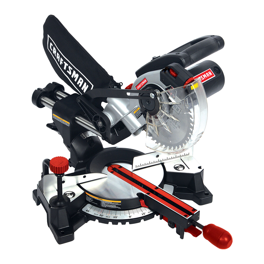
Operator's Manual
CRRFrSr4RH °
7-1/4 in. SLiDiNG COMPOUND
MITER SAW WiTH LASER TRAC ®
Model No. 137.211940
C
US
CAUTION:
Before using this Miter Saw,
read this manual and follow
all its Safety Rules and
Operating Instructions
•
Safety Instructions
•
Installation
•
Operation
•
Maintenance
•
Parts List
Customer
Help
Line
For Technical
Support
1-800-843-1682
Sears
Parts
&
Repair
Center
1-800-488-1222
Sears, Roebuck
and Co., Hoffman Estates, IL 60179 USA
Visit our Craftsman
website:
www.sears.com/craftsman
Part No. 137211940001
Printed in China
Advertisement
Table of Contents
Troubleshooting

Related Manuals for Craftsman 21194 - 7-1/4 in. Sliding Compound Miter Saw


Summary of Contents for Craftsman 21194 - 7-1/4 in. Sliding Compound Miter Saw
- Page 1 • Maintenance Operating Instructions • Parts List Sears Parts & Customer Help Line For Technical Support Repair Center 1-800-843-1682 1-800-488-1222 Sears, Roebuck and Co., Hoffman Estates, IL 60179 USA Visit our Craftsman website: www.sears.com/craftsman Part No. 137211940001 Printed in China...
-
Page 2: One Year Full Warranty
CRAFTSMAN ONE YEAR FULL WARRANTY If this Craftsman tool fails due to a defect in material or workmanship within one year from the date of purchase, call 1-800-4-MY-HOME ® to arrange for free repair (or replacement if repair proves impossible). -
Page 3: Rotating Table
MOTOR Power Source ..............9Amp, 120V AC, 60Hz Speed ................. 5000 RPM (No load) Brake .................. Electric Double Insulated ..............BLADE SIZE Diameter ................7-1/4 in. Arbor size ................5/8 in. ROTATING TABLE: Diameter ................9-1/32 in. Miter Detent Stops ............0, 15, 22.5, 31.6, 45°R &... -
Page 4: Warning Icons
WARNING iCONS Your power tool and its Operator's Manual may contain "WARNING iCONS" (a picture symbol intended to alert you to, and/or instruct you how to avoid, a potentially hazardous condition). Understanding and heeding these symbols will help you operate your tool better and safer. Shown below are some of the symbols you may see. - Page 5 GENERAL SAFETY iNSTRUCTiONS DO NOT FORCE THE TOOL. It will BEFORE USING THIS POWER TOOL do the job better and safer at the rate for which it was designed. Safety is a combination of common sense, staying alert and knowing how USE THE RIGHT TOOL.
- Page 6 NOTE: G lasses orgoggles not and any other conditions that may compliance with ANSI Z87.1 could affect its operation. A guard or seriously injure you when they other part that is damaged should break. be properly repaired or replaced. 13. WEAR A FACE MASK OR DUST 20.
- Page 7 SPECiFiC SAFETY iNSTRUCTiONS USE only blade collars specified for FOR THiS COMPOUND MITER SAW your saw. DO NOT operate the miter saw NEVER use blades larger in diameter than 7-1/4 inches. until it is completely assembled and installed according to these instructions.
- Page 8 21.NEVER cutsmallpieces. I f the workpiece b eingcutwouldcause yourhandorfingers tobewithin 6-3/4in.ofthesawbladethe workpiece i s toosmall. 22.PROVIDE adequate s upport t othe sidesofthesawtableforlongwork pieces. 23.NEVER usethemitersawinan areawithflammable l iquids or gases. 24.NEVER usesolvents t oclean plastic parts. S olvents c ould possibly d issolve or otherwise damage thematerial.
-
Page 9: Power Supply Andmotor Specifications
POWER SUPPLY ANDMOTOR way. If the plug does not fit fully in the SPECiFiCATiONS outlet, reverse the plug. If it still does TheACmotorusedinthissawis not fit, contact a qualified electrician to a universal, nonreversible type. install the proper outlet. Do not change See"MOTOR"... -
Page 10: Guidelines F Orextension Cords
nowbestarted andthecutfinished. excessive h eatanddamporwetareas. 4. FUSES may"blow" o r circuit Use a separate electrical circuit breakers m aytripfrequently i f: your tools. This circuit must not be a. MOTOR isoverloaded - less than a #18 wire with a 9 A time lag overloading canoccurifyoufeed fuse. -
Page 11: Recommended Accessories
RECOMMENDED ACCESSORIES should be taken while mounting, using, and storing carbide tipped i,_ WARNING] blades to prevent accidental damage. Slight shocks, such as Use only accessories recommended for this miter striking the tip while handling, saw. Follow instructions that can seriously damage the blade. Foreign objects in the workpiece, accompany accessories. - Page 12 Supplied Not supplied Phillips Screwdriver Blade Wrench Adjustable Wrench 6mm Hex Wrench Slotted Screwdriver Combination Square COMBINATION SQUARE MUST BE TRUE Should not gap or overlap when square is flipped over (see dotted figure). Straight edge or a 3/4 in. board, this Draw light line on edge must be perfectly straight.
- Page 13 UNPACKING YOUR MITER SAW Separate all parts from the packing material. Check each one with the illustration to make certain all WARNING] items are accounted for, before To avoid injury from unexpected discarding any packing material. starting or electrical shock, do not plug the power cord into a source of power during unpacking l,dk WARNING...
- Page 14 Switch handle Upper bladeguard ON/OFF trigger switch Bevel l ockhandle Motor Hold-down c lamp Laserguide Tableinsert Miterhandle Turntable Mounting hole LaserON/OFF switch Hold-down l atch Lower bladeguard Slidecarriage Slide carriage lockknob Bevel s cale Sawblade Hand holdfor transportation Positive miter detent Positive stoplocking lever Base...
-
Page 15: Extension Cord
AMPERAGE ( AMPS) - A measure eyes.Eyeprotection s houldmeet t he oftheflowofelectric current. H igher requirements ofANSIZ.87.1(USA) o r ratings generally means thetoolis CSAZ94.3-M88 ( Canada). suitedforheavier u se. FACESHIELD - An impact r esistant ARBOR LOCK - Allows theuserto shieldthathelpstoprotect y ourface keeptheblade fromrotating while fromchips, s parks, s malldebris. -
Page 16: Woodworking Terms
POSITIVE S TOPLOCKING LEVER - KICKBACK- Sudden and unintended Locks themiter sawata preset p ositive movement of the tool or workpiece. It is stopforthedesired miterangle. typically caused by binding or pinching of the workpiece SWITCH HANDLE - Theswitch handle contains thetrigger s witchand MITER CUT - A miter is a type of joint thelaseron/offswitch. - Page 17 To empty the dust bag, squeeze the i,A WARNING metal collar and remove from exhaust To avoid injury, do not connect this port. Open zipper on underside of bag miter saw to the power source until and empty into waste container. it is completely assembled and NOTE: Check frequently and empty adjusted, and you have read and...
-
Page 18: Unlocking The Slide Carriage
UNLOCKING THE SLIDE CARRIAGE Locking (FIG. E) When transporting or storing the miter After removing the saw from the carton, saw, the cutting head should always be loosen the slide carriage lock knob locked in the down position. (1). When transporting or storing the Push the cutting head down to its miter saw, the slide carriage should lowest position. -
Page 19: Mounting The Miter Saw
result to the blade, table insert or handle. Carrying the tool by the turntable if blade strike occurs power cord could cause damage to the insulation or the wire during the cutting operation. 1. To remove, loosen and remove the connections resulting in electric shock or fire. - Page 20 plywood u sing themounting h oleson Fig. J thebase. U seC-clamps t oclamp this mounting b oard to a stable work surface attheworksite. ( Fig.I) Fig. I 3/4 Inch plywood Locate the arbor lock (5) below REMOVING OR INSTALLING motor lower cover. (Fig. K) BLADE Press the arbor lock, holding it in firmly while turning the blade...
- Page 21 NOTE: P ayattention tothepieces 5. Rotate the cover plate (3) back to its removed, noting theirposition and original position until the slot in the direction theyface.Wipetheblade cover plate engages with the cover collars cleanofanysawdust before plate screw (2). While holding the installing a newblade.
-
Page 22: Bevel Stop Adjustments
THE LASER BEAM occasional readjustments may be necessary. i,_ WARNING CAUTION=Use of controls or For your own safety, never connect adjustments or performance of the plug to power source outlet procedures other than those until all the adjustment steps specified herein may result in are complete and you have read... - Page 23 to adjust the stop bolt (3) depth in 45 ° Bevel Adjustment (Fig. P) or out to increase or decrease the Loosen the bevel lock handle (8) bevel angle. and tilt the cutting head completely to the left. Tilt the cutting arm to back to the right at 90 °...
-
Page 24: Miter Angle Adjustment
MITER SCALE iNDiCATOR MITER ANGLE ADJUSTMENT (FIG. ADJUSTMENT (FIG. Q) The sliding compound miter saw scale Move the table to the 0° positive can be easily read, showing miter stop. angles from 0 ° to 45 ° to the left, and 0 ° Loosen the screw (4) that holds the to 45 °... -
Page 25: Adjusting Cutting Depth
SETTING CUTTING DEPTH (FIG. S) Adjust the stop knob (1) to touch The depth of cut can be preset for even the stop plate (2). and repetitive shallow cuts. Recheck the blade depth by 1. Adjust the cutting head down (See moving the cutting head front to CUTTING HEAD section) until the back through the full motion of a cut... -
Page 26: Troubleshooting Guide
SAFETY iNSTRUCTiONS FOR BASIC o Tighten the cover plate screw. SAW OPERATION o Check for damaged parts. Check for: BEFORE USING THE MITER SAW o Alignment of moving parts o Damaged electric cords i,A WARNING] o Binding of moving parts To avoid mistakes that could cause o Mounting holes... -
Page 27: Plan Your Work
diameter b lade forthematerial and in a solidly braced, fixed position. thetypeofcutting youplantodo.Do CAUTION: This machine is not notusethinkerfblades. designed for cutting masonry, o Makesurethebladeis sharp, masonry products, ferrous metals undamaged andproperly aligned. (steel, iron, and iron-based metals.) Withthesawunplugged, push Use this miter saw to cut only thecuttingarmallthewaydown. - Page 28 "no hands zone" area marked on the A sudden slip could cause your fingers or hand to move into the blade. saws table. o When cutting odd shaped DO NOT OVER-REACH workpieces, plan your work so it will not bind in the blade and cause Keep good footing and balance.
-
Page 29: Basic Saw Operations
BODY AND HAND POSITION (FIG. T) Fig. T WARNING] the cutting area. Proper Never place hands near positioning of your body and hands when operating the miter No Hand Zone saw will make cutting easier and safer. Keep children away. Keep all visitors at a safe distance from the 13-1/2 in. - Page 30 I WARNINGi Fig. U To avoid injury from materials being thrown, always unplug the saw to avoid accidental starting, and remove small pieces of material from the table cavity. MITER CUT (FIG. W) SLiDiNG CARRIAGE SYSTEM (FIG. 1. When a miter cut is required, unlock the miter table by turning the miter handle (1) counterclockwise.
- Page 31 BEVEL CUT (FIG. X) Fig. Y 1. When a bevel cut is required, loosen the bevel lock handle (1) by turning it clockwise. Tilt the cutting head to the desired angle, as shown on the bevel scale (2). The blade can be positioned at any angle, from a 90 °...
- Page 32 ToSlideCut Wide Boards (Fig. Z) CUTTING BOWED MATERIAL (FIG. 1. Unlock the carriage lock handle (1) and allow the cutting head i_ WARNING assembly to move freely. To avoid injury from materials being Set both the desired bevel angle thrown, always unplug the saw and/or the miter angle and lock into to avoid accidental starting and...
- Page 33 theworkpiece a ndposition onthe Fig. CO tablesotheinside tip oftheblade is positioned o nthe line.Usea holddown clamptosecure the workpiece. 2. Lower t hecuttinghead sothetip of thebladetouches thetopsurface workpiece a tthemarked line. 3. While holding t heupper a rmin position, turnthestopknob(2)until ittouches thestopplate(1). 3-1/4 in.
- Page 34 CUTTING BASEMOLDING (FIG. EE) angles that, when added to_ Base moldings and many other equal exactly 90 °. moldings can be cut on a compound Most crown molding has a top rear miter saw. The setup of the saw angle (the section that fits flat against depends on molding characteristics the ceiling) of 52°and a bottom rear and application, as shown.
-
Page 35: Type Of Cut
Bevel/Miter S ettings BEVEL MITER TYPE OF CUT SETTING SETTING inside corner-Left side 33.9 ° 31.6 o Right Position top of molding against fence. i2. Miter table set at RIGHT 31.6 °. 3. LEFT side is finished piece. inside corner-Right side 33.9 °... - Page 36 CROWN MOLDING CHART Compound Miter saw Miter and bevel Angle settings Wall to Crown Molding Angle 52/38 ° C_wn Molding 45/45 ° C_wn Molding 52/38 ° Crown Molding 45/45 ° Crown Molding Angle Miter Bevel Miter Bevel Angle Miter Bevel Miter Bevel Between...
-
Page 37: Maintenance
MAINTENANCE NOTE: To reinstall the same brushes, first make sure the brushes go back in DANGER the way they came out. This will avoid To avoid injury, never put lubricants a break-in period that reduces motor on the blade while it is spinning. performance and increases wear. - Page 38 SAWDUST Fig. II Periodically, sawdust will accumulate under the work table and base. This could cause difficulty in the movement of the worktable when setting up a miter cut. Frequently blow out or vacuum up the sawdust. Central pivot of i,A WARNING plastic guard Chop pivot...
-
Page 39: Troubleshooting
i,A WARNING To avoid injury from accidental starting, always turn switch OFF and unplug the tool before moving, replacing the blade or making adjustments. TROUBLESHOOTING GUIDE = MOTOR SUGGESTED CORRECTIVE PROBLEM PROBLEM CAUSE ACTION Brake does 1. Motor brushes not sealed 1. -
Page 40: Eye Protection
TROUBLESHOOTING GUIDE =SAW OPERATION SUGGESTED CORRECTIVE PROBLEM PROBLEM CAUSE ACTION Blade hits table. 1. Misalignment. 1. See ADJUSTMENT -Setting Cutting Depth section. Angle of cut not 1. Miter table unlocked. 1. See OPERATION - Miter Angle accurate. Can 2. Sawdust under table. Adjustment section. - Page 41 MITER SAW MODEL NO. 137.211940 WARNING] When servicing use only CRAFTSMAN replacement parts. Use of any other parts many create a HAZARD or cause product damage. Any attempt to repair or replace electrical parts on this Miter Saw may create a HAZARD unless repair is done by a qualified service technician.
-
Page 42: Miter Saw
7=1/4 in. COMPOUND MITER SAW MODEL NO. 137.211940 SCHEMATIC OKBA OKTS OKTQ\ 0C_'5 OJBO 2TgR _2CD2 2RSH... - Page 43 7=1/4 in. COMPOUND MITER SAW MODEL NO. 137.211940 PARTS LiST FOR MOTOR Size I.D. Description Q'l'y 0HX7 NEEDLE ROLLER BEARING 0iX2 HEX. SOC. SETSCREW M5_0.8-6 0KC© CR. RE. PAN HEAD TAPPING & WASHER SCREW M5 _ 12-65 0KNE HEX. NUT M6"1.0 T=5 0©BE BRUSH HOLDER ASS'Y...
- Page 44 Your Home For expert troubleshooting and home solutions advice: manage www.managernyhorne.com For repair - in your home - of all major brand appliances, lawn and garden equipment, or heating and cooling systems, no matter who made it, no matter who sold it! For the replacement parts, accessories and owner's manuals that you need to do-it-yourself.
Need help?
Do you have a question about the 21194 - 7-1/4 in. Sliding Compound Miter Saw and is the answer not in the manual?
Questions and answers