Advertisement
Table of Contents
- 1 One Year Full Warranty
- 2 Warning Icons
- 3 General Safety Instructions
- 4 Recommended Accessories
- 5 Installing the Hold-Down Clamp
- 6 Bevel Stop Adjustment
- 7 Miter Angle Adjustment
- 8 Miter Scale Indicator Adjustment
- 9 Operation
- 10 Plan y Our W Ork
- 11 Slide Cutting Wide Boards
- 12 Cutting Bowed Material
- 13 Crown Molding Chart
- 14 Maintenance
- 15 Lower Blade Guard
- 16 Miter Saw
- Download this manual
Operator's Manual
®
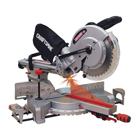
12 in. SLiDiNG COMPOUND
MITER SAW WiTH LASER TRAC ®
Model No. 137.212390
\\
\
C
us
CAUTION:
Before using this Miter Saw,
read this manual and follow
all its Safety Rules and
Operating Instructions
•
Safety Instructions
•
Installation
•
Operation
•
Maintenance
•
Parts List
Customer
Help
Line
For Technical
Support
1-800-843-1682
Sears
Parts
&
Repair
Center
1-800-488-1222
Sears, Roebuck and Co., Hoffman Estates, IL 60179 USA
Visit our Craftsman
website:
www.sears.comlcraftsman
Part No. 137212390001
Printed in China
Advertisement
Table of Contents

Related Manuals for Craftsman 21239 - 12 in. Sliding Compound Miter Saw


Summary of Contents for Craftsman 21239 - 12 in. Sliding Compound Miter Saw
- Page 1 Safety Rules and • Parts List Operating Instructions Sears Parts & Customer Help Line For Technical Support Repair Center 1-800-843-1682 1-800-488-1222 Sears, Roebuck and Co., Hoffman Estates, IL 60179 USA Visit our Craftsman website: www.sears.comlcraftsman Part No. 137212390001 Printed in China...
-
Page 2: One Year Full Warranty
Tools Needed for Assembly ....CRAFTSMAN ONE YEAR FULL WARRANTY If this Craftsman tool fails due to a defect in material or workmanship within one year from the date of purchase, call 1-800-4-MY-HOME ®to arrange for free repair (or replacement if repair proves impossible). -
Page 3: Warning Icons
WARNING ICONS Your p ower tool and its Operator's Manual may contain "WARNING ICONS" (a picture symbol intended to alert you to, and/or instruct you how to avoid, a potentially hazardous condition). Understanding and heeding these symbols will help you operate your tool better and safer. Shown below are some of the symbols you may see. -
Page 4: General Safety Instructions
GENERAL SAFETY iNSTRUCTiONS power which will cause the tool to overheat. BEFORE USING THIS POWER TOOL The table on page 7 shows the correct size to use depending on cord length and Safety is a combination of common sense, nameplate ampere rating. If in doubt, use the staying alert and knowing how to use your power next heavier gauge. - Page 5 1 &CHECK FOR DAMAGED PARTS. Before further use ofthe tool, aguard o rother part that isdamaged should becarefully checked todetermine that i twill o perate properly and perform itsintended function - check for alignment ofmoving parts, binding ofmoving parts, breakage ofparts, mounting and any other conditions...
- Page 6 SPECIFIC SAFETY INSTRUCTIONS FOR THIS 21 .NEVER cut small pieces. If the workpiece COMPOUND MITER SAW being cut would cause your hand or fingers to be within 8-3/4 in. of the saw blade the 1. DO NOT operate the miter saw until it is workpiece is too small.
- Page 7 ELECTRICAL REQUIREMENTS - cont'd FUSES may "blow" or circuit breakers may trip DOUBLE iNSULATED frequently The power tool is double insulated to provide a. MOTOR is overloaded - overloading double thickness of insulation between you and occur if you feed too rapidly or make too tool's electrical system.
-
Page 8: Recommended Accessories
RECOMMENDED ACCESSORIES Supplied Not supplied ,_ WARNING • Use only accessories recommended this miter saw. Follow instructions that Blade Wrench Adjustable Wrench accompany accessories. Use of improper accessories may cause hazards. • The use of any cutting tool except 12 in. Hex Key saw blades which meet the requirements... - Page 9 UNPACKING YOUR MITER SAW 3. Separate all parts from the packing material. Check each one with the illustration to make certain all items are accounted for, before [_t_ WARNING] discarding any packing material. To avoid injury from unexpected starting or electrical shock, do not plug the power cord...
- Page 10 Switch Handle Dust Lower Blade Guard Bevel Detent Pin_ Hold-down Clam Guide insert Sliding Base Positive Stop Locking Lever Left Table Mounting Hole Stop Latch Knob Carrying Slide Carriage Lock Knob Laser ON/OFF Switch ON/OFF Trigger ht Extension Table Switch Table Lock Knob Motor...
- Page 11 POSITIVE STOP LOCKING LEVER - Locks AMPERAGE (AMPS) - A measure of the flow of electric current. Higher ratings generally means the miter saw at a preset positive stop for the desired tool is suited for heavier use. miter angle. SWITCH HANDLE - The switch...
- Page 12 RELEASING CUTTING HEAD (FIG. D) Estimated Assembly Time: 5 - 10 minutes Unlocking I,A WARNING] WARNING To avoid injury, do not connect this miter To avoid injury and damage to the saw, saw to the power source until it is completely transport and store the miter saw with the assembled...
-
Page 13: Installing The Hold-Down Clamp
Toempty the dust bag, squeeze the metal collar 1. Loosen the miter handle (1). Lift up the and remove from exhaust port. Open z ipper on positive stop locking lever (2) and position underside ofbag and empty into waste c ontainer. the table to left 15 °. - Page 14 Place the blade end wrench over the arbor Fig.I bolt. 1. Miter saw base 2. Hex head bolt Fig.K 3. Rubber washer 4. Flat washer 5. Workbench 6. Flat washer 7. Lockwasher 8. Hex nut 9. Jam nut NOTE: Mounting hardware is not included with this tool.
- Page 15 INSTALLING BLADE (FIG. Your tool is equipped with the Laser Trac ® cutting K, L, M) guide using Class II laser beam. The laser beam WARNING] will enable to preview the saw blade path on the stock to be cut before starting the miter saw. Un-plug the miter saw before changing/ This laser guide is powered by the transformed installing...
-
Page 16: Bevel Stop Adjustment
BEVEL STOP ADJUSTMENT 45 ° Bevel Adjustment (Fig. P) 1. Loosen the bevel lock handle (7) and tilt the WARNING] cutting head completely to the left. 2. Using a combination square, check to see if To avoid injury from an accidental start, make the blade angle is 45 °... -
Page 17: Miter Scale Indicator Adjustment
3. Ifthe desired angle i sone ofthe nine p ositive SETTING CUTTING DEPTH (FIG. S) stops, release the positive stop locking lever, The depth ofcut c an bepreset for e ven a nd making sure t he lever snaps into position, repetitive shallow cuts. -
Page 18: Operation
SAFETY iNSTRUCTiONS FOR BASIC SAW any way, or any electrical parts don't work, OPERATION turn the saw off and unplug it. • Replace bent, damaged, missing or defective BEFORE USING THE MITER SAW parts before using the saw again. • Maintain tools with care. -
Page 19: Plan Y Our W Ork
PLAN Y OUR W ORK workpiece, fence and table that will let the • Use the right tool. Don't force a tool or workpiece shift after it is cut. attachment todoajob itwas not d esigned • Keep the cut off piece free to move sideways todo. - Page 20 BASIC SAW OPERATIONS BODY AND HAND POSITION (FIG. U) WARNING] I,A WARNING] For your convenience, your saw has a blade area. Proper positioning of your brake. The brake is not a safety device. Never Never place hands near the cutting body and hands when operating the rely on it to replace the proper use of the...
- Page 21 Unlock the fence cam locking lever (1) by WARNING pushing it toward the rear of the machine. Extend the fence (2) by sliding it out to match To avoid injury from materials being thrown, the degree of the bevel cut. Lock the fence always unplug the saw to avoid accidental cam locking lever by pushing it IN toward...
-
Page 22: Slide Cutting Wide Boards
COMPOUND CUT (FIG. BB) WARNING] A compound cut is the combination of a miter The sliding fence must be extended to the left and a bevel cut simultaneously• 1. Loosen the bevel lock handle (1) and position when making bevel cuts. The sliding fences note three bevel angles where the user must the cutting head at the desired bevel position•... -
Page 23: Cutting Bowed Material
7. Slowly move t he switch handle toward the Fig. E E fence, completing the cut. 8. Release the trigger and allow the blade to stop s pinning before allowing the cutting head toraise. Fig. C C AUXILIARY WOOD FENCE (FIG. FF) When making multiple or repetitive cuts that result in cut-off pieces of one inch or less, it is possible for the saw blade to catch the cut-off... - Page 24 CUTTING BASE MOLDING (FIG. GG) Bevel/Miter Settings Base moldings and many other moldings can Fig. II be cut on a compound miter saw. The setup of the saw depends on molding characteristics Settings for standard crown molding lying flat application, as shown.
-
Page 25: Crown Molding Chart
CROWN MOLDING CHART Compound Miter saw Miter and bevel Angle settings Wall to Crown Molding Angle 52/38 _Crown Molding 45/45 ' Crown Molding 52/38 _Crown Molding 45/45 ' Crown Molding Angle Miter Bevel Miter Bevel Angle Miter Bevel Miter Bevel Between Between Setting... -
Page 26: Maintenance
MAINTENANCE I,A WARNING] i_ WARNING • Do not use solvents on the guard. They Never put lubricants on the blade while it is could make the plastic "cloudy" brittle, spinning. • When cleaning the lower guard, unplug the ,_ WARNING saw from the power source receptacle avoid unexpected start-up. - Page 27 WARNING] To avoid injury from accidental starting, always turn switch OFF and unplug the tool before moving, replacing the blade or making adjustments. TROUBLESHOOTING GUIDE - MOTOR PROBLEM PROBLEM CAUSE SUGGESTED CORRECTIVE ACTION Brake does not Motor brushes not sealed or lightly 1.
-
Page 28: Miter Saw
12 in. COMPOUND MITER SAW MODEL NO. 137.212390 I_]L WARNING] When servicing use only CRAFTSMAN replacement parts. Use of any other parts many create a HAZARD or cause product damage. Any attempt to repair or replace electrical parts on this... - Page 29 12 in. COMPOUND MITER SAW MODEL NO. 137.212390 SCHEMATIC...
- Page 30 12 in. COMPOUND MITER SAW MODEL NO. 137.212390 PARTS LiST FOR SAW SCHEMATIC I.D. Description Size 0DTH CENTER BOLT 0J6A FLAT WASHER q)8_16-2.5 0J74 FLAT WASHER 1/4_5/&3/32 0JAZ WAVE WASHER WW-6 0JPF HEX. HD. BOLT M6_1.0-25 0JXB HEX. SOC. SET SCREW M6_1.0-16 0JXG HEX.
- Page 31 12 in. COMPOUND MITER SAW MODEL NO. 137.212390 SCHEMATIC /°...
- Page 32 12 in. COMPOUND MITER SAW MODEL NO. 137.212390 PARTS LiST FOR MOTOR Size I.D. Description 0JCF SPRING PiN cp4-30 0JX2 HEX. SOC SETSCREW M5"0.8-6 0K44 CR. RE. PAN HD. SCREW & WASHER M5_0.8 - 12 0KCP CR. RE. PAN HEAD TAPPING & WASHER SCREW M5 *_ 12-60 M5*g.8-6 0KLA...
- Page 34 Your Home For expert troubleshooting and home solutions advice: www.managemyhome.com For repair - in your home - of all major brand appliances, lawn and garden equipment, or heating and cooling systems, no matter who made it, no matter who sold it! For the replacement parts, accessories and owner's manuals that you need to do-it-yourself.
Need help?
Do you have a question about the 21239 - 12 in. Sliding Compound Miter Saw and is the answer not in the manual?
Questions and answers