DeWalt DWD112, DWD112S, DWD115S - Impact Driver Manual
- User manual ,
- Instruction manual (113 pages) ,
- Original instructions manual (21 pages)
Advertisement
Technical Data
| DWD112 | DWD112S | DWD115S | ||
| Voltage | VAC | 230 | 230 | 230 |
| Type | 1/3 | 1/3 | 1/3 | |
| Power output | W | 701 | 701 | 701 |
| No load speed | min‑1 | 0–2500 | 0–2500 | 0–2500 |
| Maximum drilling range steel/wood/concrete | mm | 10/25/13 | 10/25/13 | 10/25/13 |
| Torque | Nm | 10.9 | 10.9 | 10.9 |
| Chuck spindle thread size | UNF | 1/2"x20 | 1/2"x20 | 1/2"x20 |
| Maximum chuck capacity | mm | 10 | 10 | 10 |
| Weight | kg | 1.9 | 1.83 | 1.96 |
| Noise values and/or vibration values (triax vector sum) according to EN62841‑2‑1: | ||||
| LPA (emission sound pressure level) | dB(A) | 86 | 86 | 88 |
| LWA (sound power level) | dB(A) | 94 | 94 | 96 |
| K (uncertainty for the given sound level) | dB(A) | 5 | 5 | 5 |
| Drilling into metal | ||||
| Vibration emission value ah, D = | m/s2 | 6.3 | 6.3 | 6.4 |
| Uncertainty K = | m/s2 | 1.5 | 1.5 | 2.4 |
The vibration and/or noise emission level given in this information sheet has been measured in accordance with a standardised test given in EN62841 and may be used to compare one tool with another. It may be used for a preliminary assessment of exposure.

The declared vibration and/or noise emission level represents the main applications of the tool. However if the tool is used for different applications, with different accessories or poorly maintained, the vibration and/or noise emission may differ. This may significantly increase the exposure level over the total working period.
An estimation of the level of exposure to vibration and/or noise should also take into account the times when the tool is switched off or when it is running but not actually doing the job. This may significantly reduce the exposure level over the total working period.
Identify additional safety measures to protect the operator from the effects of vibration and/or noise such as: maintain the tool and the accessories, keep the hands warm (relevant for vibration), organisation of work patterns.
Definitions: Safety Guidelines
The definitions below describe the level of severity for each signal word. Please read the manual and pay attention to these symbols.

Indicates an imminently hazardous situation which, if not avoided, will result in death or serious injury.
Indicates a potentially hazardous situation which, if not avoided, could result in death or serious injury.

Indicates a potentially hazardous situation which, if not avoided, may result in minor or moderate injury.
NOTICE: Indicates a practice not related to personal injury which, if not avoided, may result in property damage.
 Denotes risk of electric shock.
![]() Denotes risk of fire.
Denotes risk of fire.
GENERAL POWER TOOL SAFETY WARNINGS

Read all safety warnings, instructions, illustrations and specifications provided with this power tool. Failure to follow all instructions listed below may result in electric shock, fire and/or serious injury.
The term "power tool" in the warnings refers to your mains-operated (corded) power tool or battery-operated (cordless) power tool.
- Work Area Safety
- Keep work area clean and well lit. Cluttered or dark areas invite accidents.
- Do not operate power tools in explosive atmospheres, such as in the presence of flammable liquids, gases or dust. Power tools create sparks which may ignite the dust or fumes.
- Keep children and bystanders away while operating a power tool. Distractions can cause you to lose control.
- Electrical Safety
- Power tool plugs must match the outlet. Never modify the plug in any way. Do not use any adapter plugs with earthed (grounded) power tools. Unmodified plugs and matching outlets will reduce risk of electric shock.
- Avoid body contact with earthed or grounded surfaces, such as pipes, radiators, ranges and refrigerators. There is an increased risk of electric shock if your body is earthed or grounded.
- Do not expose power tools to rain or wet conditions. Water entering a power tool will increase the risk of electric shock.
- Do not abuse the cord. Never use the cord for carrying, pulling or unplugging the power tool. Keep cord away from heat, oil, sharp edges or moving parts. Damaged or entangled cords increase the risk of electric shock.
- When operating a power tool outdoors, use an extension cord suitable for outdoor use. Use of a cord suitable for outdoor use reduces the risk of electric shock.
- If operating a power tool in a damp location is unavoidable, use a residual current device (RCD) protected supply. Use of an RCD reduces the risk of electric shock.
- Personal Safety
- Stay alert, watch what you are doing and use common sense when operating a power tool. Do not use a power tool while you are tired or under the influence of drugs, alcohol or medication. A moment of inattention while operating power tools may result in serious personal injury.
- Use personal protective equipment. Always wear eye protection. Protective equipment such as a dust mask, non-skid safety shoes, hard hat or hearing protection used for appropriate conditions will reduce personal injuries.
- Prevent unintentional starting. Ensure the switch is in the off‑position before connecting to power source and/or battery pack, picking up or carrying the tool. Carrying power tools with your finger on the switch or energising power tools that have the switch on invites accidents.
- Remove any adjusting key or wrench before turning the power tool on. A wrench or a key left attached to a rotating part of the power tool may result in personal injury.
- Do not overreach. Keep proper footing and balance at all times. This enables better control of the power tool in unexpected situations.
- Dress properly. Do not wear loose clothing or jewellery. Keep your hair and clothing away from moving parts. Loose clothes, jewellery or long hair can be caught in moving parts.
- If devices are provided for the connection of dust extraction and collection facilities, ensure these are connected and properly used. Use of dust collection can reduce dust-related hazards.
- Do not let familiarity gained from frequent use of tools allow you to become complacent and ignore tool safety principles. A careless action can cause severe injury within a fraction of a second.
- Power Tool Use and Care
- Do not force the power tool. Use the correct power tool for your application. The correct power tool will do the job better and safer at the rate for which it was designed.
- Do not use the power tool if the switch does not turn it on and off. Any power tool that cannot be controlled with the switch is dangerous and must be repaired.
- Disconnect the plug from the power source and/or remove the battery pack, if detachable, from the power tool before making any adjustments, changing accessories, or storing power tools. Such preventive safety measures reduce the risk of starting the power tool accidentally.
- Store idle power tools out of the reach of children and do not allow persons unfamiliar with the power tool or these instructions to operate the power tool. Power tools are dangerous in the hands of untrained users.
- Maintain power tools and accessories. Check for misalignment or binding of moving parts, breakage of parts and any other condition that may affect the power tool's operation. If damaged, have the power tool repaired before use. Many accidents are caused by poorly maintained power tools.
- Keep cutting tools sharp and clean. Properly maintained cutting tools with sharp cutting edges are less likely to bind and are easier to control.
- Use the power tool, accessories and tool bits etc. in accordance with these instructions, taking into account the working conditions and the work to be performed. Use of the power tool for operations different from those intended could result in a hazardous situation.
- Keep handles and grasping surfaces dry, clean and free from oil and grease. Slippery handles and grasping surfaces do not allow for safe handling and control of the tool in unexpected situations.
- Service
- Have your power tool serviced by a qualified repair person using only identical replacement parts. This will ensure that the safety of the power tool is maintained.
Additional Specific Safety Rules for Drills
- Wear ear protectors. Exposure to noise can cause hearing loss.
- Use auxiliary handles supplied with the tool. Loss of control can cause personal injury.
- Hold the power tool by insulated gripping surfaces when performing an operation where the cutting tool may contact hidden wiring or its own cord. Cutting accessory contacting a "live" wire may make exposed metal parts of the power tool "live" could give the operator an electric shock.
- Use clamps or other practical way to secure and support the workpiece to a stable platform. Holding the work by hand or against your body is unstable and may lead to loss of control.
- Wear safety goggles or other eye protection. Drilling operations cause chips to fly. Flying particles can cause permanent eye damage.
- Bits and tools get hot during operation. Wear gloves when touching them.
- Keep handles dry, clean, free from oil and grease. it is recommended to use rubber gloves. This will enable better control of the tool.
We recommend the use of a residual current device with a residual current rating of 30mA or less.
Residual Risks
The following risks are inherent to the use of drills:
- Injuries caused by touching the rotating parts or hot parts of the tool.
In spite of the application of the relevant safety regulations and the implementation of safety devices, certain residual risks cannot be avoided. These are:
- Impairment of hearing.
- Risk of squeezing fingers when changing accessories.
- Health hazards caused by breathing dust developed when working in wood.
- Risk of personal injury due to flying particles.
- Risk of personal injury due to prolonged use.
Electrical Safety
The electric motor has been designed for one voltage only. Always check that the power supply corresponds to the voltage on the rating plate.

Your DeWALT tool is double insulated in accordance with EN62841; therefore no earth wire is required.
If the supply cord is damaged, it must be replaced only by DeWALT or an authorised service organisation.
Mains Plug Replacement
(U.K. & Ireland Only)
If a new mains plug needs to be fitted:
- Safely dispose of the old plug.
- Connect the brown lead t o the live terminal in the plug.
- Connect the blue lead to the neutral terminal.
No connection is to be made to the earth terminal.
Follow the fitting instructions supplied with good quality plugs. Recommended fuse: 13 A.
Using an Extension Cable
If an extension cable is required, use an approved 3–core extension cable suitable for the power input of this tool (see Technical Data).The minimum conductor size is 1.5 mm2; the maximum length is 30 m.
When using a cable reel, always unwind the cable completely.
Package Contents
The package contains:
1 Drill
1 Chuck key (DWD112)
1 Instruction manual
- Check for damage to the tool, parts or accessories which may have occurred during transport.
- Take the time to thoroughly read and understand this manual prior to operation.
Markings on Tool
The following pictograms are shown on the tool:
 Read instruction manual before use.
Date Code Position (Fig. A)
The production date code  consists of a 4-digit year followed by a 2-digit week and is extended by a 2-digit factory code.
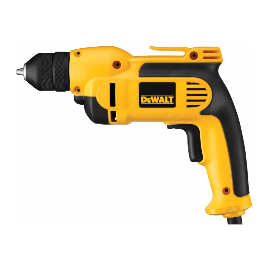
Description
Never modify the power tool or any part of it. Damage or personal injury could result.

- Variable speed trigger switch
- Lock-on button (DWD112, DWD112S)
- Forward/reverse button
- Chuck
- Main handle
Intended Use
These heavy-duty V.S.R. drills are designed for professional drilling.
DO NOT use under wet conditions or in the presence of flammable liquids or gases.
These heavy-duty drills are professional power tools.
DO NOT let children come into contact with the tool.
Supervision is required when inexperienced operators use this tool.
- Young children and the infirm. This appliance is not intended for use by young children or infirm persons without supervision.
- This product is not intended for use by persons (including children) suffering from diminished physical, sensory or mental abilities; lack of experience, knowledge or skills unless they are supervised by a person responsible for their safety. Children should never be left alone with this product.
OPERATION
Instructions for Use
Always observe the safety instructions and applicable regulations.
To reduce the risk of serious personal injury, turn tool off and disconnect tool from power source before making any adjustments or removing/installing attachments or accessories. An accidental start-up can cause injury.
Proper Hand Position
(Fig. A, C)
To reduce the risk of serious personal injury, ALWAYS use proper hand position as shown.
To reduce the risk of serious personal injury, ALWAYS hold securely in anticipation of a sudden reaction.
Proper hand position requires one hand under the the housing, with the other hand on the main handle  .
.

Switches
(Fig. A, B)
To start the drill, depress the trigger switch; to stop the drill, release the trigger.
A variable speed trigger switch  permits speed control. The farther the trigger is depressed, the higher the speed of the drill.
For continuous operation, press and hold the variable speed switch, move the lock-on button  up (DWD112, DWD112S) then release the switch.
NOTE: Use lower speeds for starting holes without a center punch, drilling in metal or plastics, driving screws or drilling ceramics. Higher speeds are better for drilling wood and composition boards and using abrasive and polishing accessories.
The forward/reverse lever  is used for withdrawing bits from tight holes and removing screws. It is located above the trigger switch. To reverse the motor, release the trigger switch FIRST and then push the lever to the right. After any reversing operations, return lever to forward position.
To stop continuous operation, press the switch briefly and release it. Always switch the tool off when work is finished and before unplugging.

Drilling
To reduce the risk of personal injury, ALWAYS ensure workpiece is anchored or clamped firmly. If drilling thin material, use a wood "back-up" block to prevent damage to the material.
- Use sharp drill bits only. For WOOD, use twist drill bits, spade bits, power auger bits, or hole saws. For METAL, use steel twist drill bits or hole saws.
- Always apply pressure in a straight line with the bit. Use enough pressure to keep drill biting, but do not push hard enough to stall the motor or deflect the bit.
- Hold tool firmly with both hands to control the twisting action of the drill.
- IF DRILL STALLS, it is usually because it is being overloaded or improperly used. RELEASE TRIGGER IMMEDIATELY, remove drill bit from work, and determine cause of stalling. DO NOT CLICK TRIGGER ON AND OFF IN AN ATTEMPT TO START A STALLED DRILL. THIS CAN DAMAGE THE DRILL.
- To minimize stalling or breaking through the material, reduce pressure on drill and ease the bit through the last fractional part of the hole.
- Keep the motor running when pulling the bit back out of a drilled hole. This will help prevent jamming.
- With variable speed drills there is no need to center punch the point to be drilled. Use a slow speed to start the hole and accelerate by squeezing the trigger harder when the hole is deep enough to drill without the bit skipping out.
Drilling in Metal
Start drilling with slow speed and increase to full power while applying firm pressure on the tool. A smooth even flow of metal chips indicates the proper drilling rate. Use a cutting lubricant when drilling metals. The exceptions are cast iron and brass which should be drilled dry.
NOTE: Large 8 mm to 13 mm holes in steel can be made easier if a pilot hole 4 mm to 5 mm is drilled first.
Drilling in Wood
Start drilling with slow speed and increase to full power while applying firm pressure on the tool. Holes in wood can be made with the same twist drills used for metal. These bits may overheat unless pulled out frequently to clear chips from the flutes. Work that is apt to splinter should be backed up with a block of wood.
Keyless Chuck
DWD112S, DWD115S
The DWD112S, DWD115S features a keyless chuck  for greater convenience. To insert a drill bit or other accessory, follow the steps listed below.

- Grasp the rear half of the chuck with one hand and use your other hand to rotate the front half counterclockwise, as shown in Figure D. Rotate far enough so that the chuck opens sufficiently to accept the desired accessory.
- Insert the bit or other accessory about 19 mm into the chuck and tighten securely by holding the rear half of the chuck and rotating the front portion in the clockwise direction. When the chuck is nearly tightened, you will hear a clicking sound. After 4–6 clicks, the chuck is securely tightened around the accessory.
- To release the accessory, repeat step 1 listed above.
Do not attempt to tighten drill bits (or any other accessory) by gripping the front part of the chuck and turning the tool on. Damage to the chuck and personal injury may result.
Keyless Chuck Removal
(Fig. E)
Tighten the chuck around the shorter end of a hex key (not supplied) of 6 mm or greater size. Using a soft hammer or piece of wood, strike the longer end in the counterclockwise direction. This will loosen the chuck so that it can be unscrewed by hand.
Keyless Chuck Installation
(Fig. F)
Screw the chuck on by hand as far as it will go. Tighten the chuck around the shorter end of a 6 mm or larger hex key (not supplied) strike the longer end in the clockwise direction with a soft hammer.
Keyed Chuck
(Fig. A, G, H)
DWD112
The DWD112 features a keyed chuck . To insert a drill bit or other accessory, follow the steps listed below.

- Open the chuck jaws by turning collar by hand and insert the shank of the bit about 19 mm into chuck. Tighten the chuck collar by hand.
- Place chuck key in each of the three holes, and tighten in clockwise direction. It's important to tighten chuck with all three holes.
To release the bit, turn the chuck counterclockwise in just one hole, then loosen the chuck by hand.
Removal of Keyed Chuck (Fig. G)
Tighten the chuck around the shorter end of a hex key (not supplied) of 6 mm or greater size. Using a soft hammer, strike the key sharply in the counterclockwise direction when viewed from the front of the tool. This will loosen the chuck so that it can be removed by hand.
Keyed Chuck Installation (Fig. H)
Screw the chuck on by hand as far as it will go. Insert the shorter end of a hex key (not supplied) of 6 mm or greater size and strike it in the clockwise direction with a soft hammer.
MAINTENANCE
Your power tool has been designed to operate over a long period of time with a minimum of maintenance. Continuous satisfactory operation depends upon proper tool care and regular cleaning.
To reduce the risk of serious personal injury, turn tool off and disconnect tool from power source before making any adjustments or removing/installing attachments or accessories. An accidental start-up can cause injury.
Motor Brushes
DeWALT uses an advanced brush system which automatically stops the drill when the brushes wear out. This prevents serious damage to the motor. Brushes must be replaced by an authorised DeWALT repair agent with identical replacement parts.
Lubrication
Your power tool requires no additional lubrication.
Cleaning
Electrical shock and mechanical hazard. Disconnect the electrical appliance from the power source before cleaning.
To ensure safe and efficient operation, always keep the electrical appliance and the ventilation slots clean.
Never use solvents or other harsh chemicals for cleaning the non-metallic parts of the tool. These chemicals may weaken the materials used in these parts. Use a cloth dampened only with water and mild soap. Never let any liquid get inside the tool; never immerse any part of the tool into a liquid.
Ventilation slots can be cleaned using a dry, soft non-metallic brush and/or a suitable vacuum cleaner. Do not use water or any cleaning solutions. Wear approved eye protection and an approved dust mask.
Optional Accessories
Since accessories, other than those offered by DeWALT, have not been tested with this product, use of such accessories with this tool could be hazardous. To reduce the risk of injury, only DeWALT recommended accessories should be used with this product.
Consult your dealer for further information on the appropriate accessories.
Documents / Resources
References
Download manual
Here you can download full pdf version of manual, it may contain additional safety instructions, warranty information, FCC rules, etc.
Download DeWalt DWD112, DWD112S, DWD115S - Impact Driver Manual
Advertisement


Need help?
Do you have a question about the DWD112 and is the answer not in the manual?
Questions and answers