Table of Contents
Advertisement
POWER
PHONES
Natural Sound AV Amplifire
Amplificateur audiovisuel "Son Naturel"
Natural Sound AV-Verstärker
Natural Sound AV-förstärkare
Amplificatore AV a suono naturale
Amplificador AV de Sonido Natural
Natural Sound AV Versterker
CINEMA DSP
7ch
NATURAL SOUND
AV AMPLIFIER
DSP–A1092
0
0
l
l
l
ON
OFF
2
2
2
3
3
3
4
4
4
5
5
5
A
B
BASS
TONE
SPEAKERS
EXTENSION
BYPASS
BASS
TREBLE
VCR 2
VIDEO AUX
TAPE (MD)
TUNER
SOURCE
0
DVD/LD
TAPE (MD)
l
l
l
2
2
2
TV/DBS
TUNER
PROGRAM
VCR 1
CD
3
3
3
VCR 2
PHONO
4
4
4
VIDEO AUX
5
L
5
5
R
SET
DELAY/C/R
MENU
/F/SWFR
BALANCE
REC OUT
VOLUME
l6
20
VCR 1
DVD/LD
l2
28
8
TV/DBS
4
40
PHONO
CD
60
2
0
–dB
EFFECT
S VIDEO
VIDEO
L AUDIO R
VIDEO AUX
OWNER'S MANUAL
MODE D'EMPLOI
BEDIENUNGSANLEITUNG
BRUKSANVISNING
MANUALE DI ISTRUZIONI
MANUAL DE INSTRUCCIONES
GEBRUIKSAANWIJZING
Advertisement
Table of Contents

Related Manuals for Yamaha DSP-A1092


Summary of Contents for Yamaha DSP-A1092
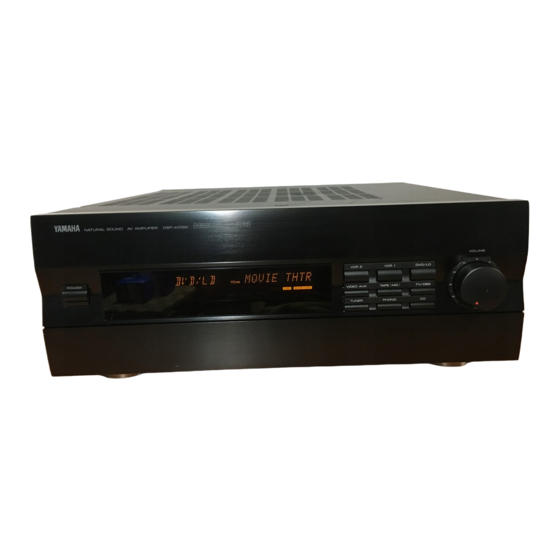
- Page 1 NATURAL SOUND AV AMPLIFIER POWER PHONES SPEAKERS Natural Sound AV Amplifire Amplificateur audiovisuel “Son Naturel” Natural Sound AV-Verstärker Natural Sound AV-förstärkare Amplificatore AV a suono naturale Amplificador AV de Sonido Natural Natural Sound AV Versterker CINEMA DSP DSP–A1092 VIDEO AUX SOURCE DVD/LD TAPE (MD)
- Page 2 Congratulations! You are the proud owner of a Yamaha Digital Sound Field Processing (DSP) System—an extremely sophisticated audio component. The DSP system takes full advantage of Yamaha’s undisputed leadership in the field of digital audio processing to bring you a whole new world of listening experiences.
-
Page 3: Precautions & Safety Instructions
YAMAHA will not be held responsible for any damage resulting from use of this unit with a voltage other than that which is specified. -
Page 4: Table Of Contents
PRECAUTIONS & SAFETY INSTRUCTIONS ...1 GETTING STARTED ...3 FEATURES ...5 SPEAKER SETUP...10 CONTROLS & THEIR FUNCTIONS...13 FRONT PANEL...13 DISPLAY PANEL ...16 CONNECTIONS...17 REAR PANEL PARTS AND THEIR FUNCTIONS ...17 REAR PANEL SWITCH AND CONTROL SETTINGS...20 GENERAL INSTRUCTIONS FOR CONNECTIONS ...20 CONNECTING AUDIO/VIDEO SOURCE EQUIPMENT TO THIS UNIT ...21... -
Page 5: Getting Started
GETTING STARTED Unpacking If you haven’t already done so, carefully remove this unit and its accessories from the box and wrapping material. You should find the unit itself and the following accessories. Remote control User function stickers Installing the Remote Control Unit Batteries Since the remote control unit will be used for many of this unit’s control operations, you should begin by installing the supplied batteries. - Page 6 Notes about the Remote Control Unit When you notice that remote control operation has become erratic, or the distance from which the remote control will function has decreased, it’s time to replace the batteries. Always replace all batteries at the same time. This remote control uses an advanced, highly directional infrared beam.
-
Page 7: Features
Extensive research into the exact nature of the sonic reflections that create the ambience of a large hall has made it possible for Yamaha engineers to bring you this same sound in your own listening room, so you’ll feel all the sound of a live concert. - Page 8 Dolby Pro Logic Surround This unit employs a Dolby Pro Logic Surround decoder similar to professional Dolby Stereo decoders used in many movie theaters. By using the Dolby Pro Logic Surround decoder, you can experience the dramatic realism and impact of Dolby Surround movie theater sound in your own home.
- Page 9 Yamaha DSP technology made it possible to present you with nearly the same sound experience as that of a large movie theater...
- Page 10 Dolby Pro Logic + 2 Digital Sound Fields Digital sound fields are created on the presence side and the rear surround side of the Dolby Pro Logic Surround-decoded sound field respectively. They create a wide acoustic environment and emphasize surround-effect in the room, letting you feel much presence as if you are watching a movie in a popular Dolby Stereo theater.
- Page 11 Video superimpose If you connect your video cassette recorder, LD player, video monitor, etc. to this unit, you can take advantage of this unit’s capability to display program titles and information for various setting changes and adjustments on your video monitor’s screen. This information will be superimposed over the video image.
-
Page 12: Speaker Setup
LFE (low frequency effect) sound with high fidelity when playing back a source with the Dolby Digital (AC-3) decoded. You may wish to choose the convenience of a Yamaha Active Servo Processing Subwoofer System, which has its own built-in power amplifier. - Page 13 Four Possible Types of Speaker System Configurations Recommended 4 Speaker System 5 Speaker System Simplest system. Good for Audio/Video sources. You can enjoy widely diffused sound By the use of center speaker, center by only adding two additional speaker sounds (dialog, vocals etc.) are units at the rear.
- Page 14 SPEAKERS. (To avoid interference, keep the speaker above or below the television monitor, or use a magnetically shielded speaker.) If using a SUBWOOFER, such as a Yamaha Active Servo Subwoofer System, the position of the speaker is not so critical because low bass tones are not highly directional.
-
Page 15: Controls & Their Functions
CONTROLS & THEIR FUNCTIONS FRONT PANEL DSP–A1092 NATURAL SOUND AV AMPLIFIER POWER BASS TONE PHONES SPEAKERS EXTENSION BYPASS For control keys on the remote control unit, see pages 50 to 52. CINEMA DSP VCR 2 VIDEO AUX TUNER SOURCE DVD/LD... - Page 16 POWER Switch Turns this unit on and off. * When you press this switch to turn the power on, you will hear a click and a sound of the built-in fan rotating for a moment. Standby Indicator While the power of this unit is on, pressing the (SYSTEM POWER) OFF key on the remote control unit switches this unit to the standby mode.
- Page 17 PROGRAM Selector Sequentially selects the digital sound field processing programs in the + or – direction. SET MENU Switch Whenever pressed, selects functions in the SET MENU mode. DELAY/C/R/F/SWFR Switch Whenever pressed, selects the item of changing delay time, center speaker output level, rear speaker output level, front effect speaker output level and subwoofer output level in turn.
-
Page 18: Display Panel
DISPLAY PANEL Input Source Display Shows the currently selected input source. Multi-informatiom Display Shows the currently selected DSP program, or information for several adjustments or setting changes made on this unit. SPEAKERS A/B Indicators The indicator A or B which corresponds to the currently selected main speakers lights up. -
Page 19: Connections
REAR PANEL PARTS AND THEIR FUNCTIONS Before you start making connections make sure all related electronic components are turned OFF. PCM/ AUDIO SIGNAL AUDIO SIGNAL VIDEO SIGNAL DIGITAL IN VIDEO COAXIAL PHONO DVD/LD DVD/LD TV/DBS OPTICAL COAXIAL TUNER VCR 1 TV/DBS TAPE TAPE(MD) - Page 20 PCM/ DIGITAL IN (COAXIAL and OPTICAL) jacks Can be connected with audio/video units that have a coaxial or optical digital output jack. Connect a unit that is connected to the DVD/LD AUDIO/VIDEO SIGNAL connection jacks to the DVD/LD COAXIAL or OPTICAL jack. Connect a unit that is connected to the TV/DBS AUDIO/VIDEO SIGNAL connection jacks to the TV/DBS COAXIAL or OPTICAL jack.
- Page 21 PRE OUT Jacks Main-channel line output. Connected with jumper bars to MAIN IN jacks when the built-in amplifier is used. Connected to input jacks of external stereo power amplifier (MAIN IN or TAPE PLAY jacks of integrated amplifier or receiver) when using external amplification.
-
Page 22: Rear Panel Switch And Control Settings
REAR PANEL SWITCH AND CONTROL SETTINGS There are several switches and controls on the rear panel that you’ll have to check before operating your system, and it’s a good idea to do it before you connect cables. Locate the MAIN LEVEL slide switch (C) and FRONT MIX slide switch (B). -
Page 23: Connecting Audio/Video Source Equipment To This Unit
BASIC CONNECTIONS If you have YAMAHA audio/video unit numbered as 1, 2, 3, etc. on the rear panel, connections can be made easily by making sure to connect the output (or input) terminals of each unit to the same-numbered terminals of this unit. - Page 24 CONNECTING TO DIGITAL (OPTICAL AND COAXIAL) JACKS If your LD (DVD) player, TV/satellite tuner, etc. are equipped with coaxial or optical digital audio signal output jacks, they can be connected to this unit’s COAXIAL and/or OPTICAL digital signal input jacks. To make a connection between optical digital audio signal jacks, remove the cover from each jack, and then connect them by using a commercially available optical fiber cable that conforms to...
- Page 25 COAXIAL jack take priority. In this case, switch off the RF demodulator to listen to CD sound surely. However, if your RF demodulator is the Yamaha model APD-1, you do not have to switch it off.
- Page 26 CONNECTING TO S VIDEO JACKS If your video cassette recorder, LD player, etc. and your monitor are equipped with “S” (high-resolution) video terminals, connect them to this unit’s S VIDEO jacks, and connect this unit’s S VIDEO MONITOR OUT jack to the “S” video input of your monitor.
-
Page 27: Connecting Speaker Systems
For connecting with a monitor TV that uses a 21 pin connector for input (for Europe and U.K. models) Make a connection as figured below with a commercially available scart-plug connector cable. Monitor TV CONNECTING SPEAKER SYSTEMS Connect the SPEAKERS terminals to your speakers with wire of the proper gauge, cut as short as possible. - Page 28 CONNECTING THE MAIN SPEAKERS TO THIS UNIT One or two sets of MAIN speakers can be connected to this unit. If you use two sets of MAIN speakers, connect one set to the MAIN SPEAKERS A terminals, and connect another set to the B terminals.
- Page 29 NOTE: The speaker connections above are fine for most applications. If for some reason, however, you wish to use an external power amp for any or all of the front effect, rear and center channels, connect the line level output jack(s) for each channel to...
- Page 30 OUTPUT FRONT REAR EFFECT With some subwoofers, including the Yamaha Active Servo Processing Subwoofer System, the amplifier and subwoofer are in the same unit. COUPLER OUTPUT MAIN CH FRONT...
- Page 31 Switching the IMPEDANCE SELECTOR switch on the rear panel Select the position whose requirements your speaker system meets. Be sure to switch this only when the power of this unit is turned off. WARNING Never switch the setting of this switch when the power of this unit is on, otherwise this unit will break down.
-
Page 32: Selecting The Output Modes Suitable For Your Speaker System
SELECTING THE OUTPUT MODES SUITABLE FOR YOUR SPEAKER SYSTEM This unit provides you the following four functions to determine the method of distributing output signals to speakers suitable for your audio system. When speaker connections are all completed, select a proper position on each function to make the best use of your speaker system. - Page 33 6. MAIN SPEAKER Choices: SMALL/LARGE Preset position: LARGE SMALL: Select this position if your main speakers do not have a high ability for bass reproduction. However, if your system does not include a subwoofer, do not select this position. In this position, low bass signals (below 90 Hz) at the main channels are output from the SUBWOOFER jacks (if the SWFR or BOTH position is selected on “7.
- Page 34 METHOD OF CHANGING SELECTIONS Operations should be made watching information on this unit’s display panel or the monitor screen. 1. Turn the power of this unit on. (If you want to display information on the monitor, turn the power of the monitor on.) Front panel POWER If you will use the remote control unit, set the TIME/LEVEL·SET...
-
Page 35: Speaker Balance Adjustment
SPEAKER BALANCE ADJUSTMENT This operation uses an internal test-tone generator for balancing the levels of the main, center, rear and front effect speakers. The adjustment of each speaker output level should be done at your listening position with the remote control unit. Otherwise, the result may not be satisfactory. - Page 36 NOTE: If there is insufficient volume from the effect speakers, you may decrease the main speaker volume level by setting the MAIN LEVEL switch on the rear panel to “–10 dB”, and adjust each speaker level again. Volume controls on external power amplifiers may also be adjusted if necessary to achieve proper balance.
-
Page 37: Adjustments In The "Set Menu" Mode
ADJUSTMENTS IN THE “SET MENU” MODE The following eight types of functions maximize the performance of your system and expand your enjoyment for audio listening and video watching. 1. CENTER DELAY 2. DYNAMIC RANGE 3. LFE LEVEL 4. CENTER SPEAKER 5. - Page 38 DESCRIPTIONS OF THE FUNCTIONS 1. CENTER DELAY (Adjusting the delay of center sounds (dialog etc.)) Control range: 0 ms to 5 ms (in 1 ms step) Preset value: 0 ms This adjustment is effective only when the Dolby Digital (AC-3) is decoded and the signals of selected source encoded with the Dolby Digital (AC-3) contain center-channel signals.
- Page 39 3. LFE LEVEL (Adjusting the output level at the LFE (low frequency effect) channel) Control range: –20 dB to 0 dB (in 1 dB step) Preset value: 0 dB This adjustment is effective only when the Dolby Digital (AC-3) is decoded and the signals of selected source encoded with the Dolby Digital (AC-3) contain LFE signals.
-
Page 40: General Operation
GENERAL OPERATION PLAYING A SOURCE NOTE: If you will use the remote control unit, be sure to use it with the lid open. 1. Set the master VOLUME control to minimum. Front panel VOLUME –dB 2. Turn the power on. Front panel POWER 3. - Page 41 Notes on using the input selector buttons • Note that pressing on each input selector button selects the source which is connected to the corresponding input terminals on the rear panel. * To select the source connected to the VIDEO AUX terminals on the front panel, press VIDEO AUX.
-
Page 42: Recording A Source To Audio/Video Tape (Or Dubbing From A Tape To Another)
Notes on input mode selection • To play back a source with the Dolby Digital (AC-3) decoded, set the input mode to “AUTO”. • When you want to enjoy a source which has normal 2-channel signals with a Dolby Pro Logic Surround program, select the ANALOG mode. - Page 43 Regardless of the setting of input selector buttons, when you set the REC OUT selector to a position other than “SOURCE”, the source selected by the REC OUT selector can be recorded by other tape deck (MD recorder) and/or VCRs connected to this unit. While recording a source by setting the REC OUT selector to the position other than SOURCE as described above, the following operations can be made at the same time.
-
Page 44: Selecting Sound Field Programs
SELECTING SOUND FIELD PROGRAMS This unit has 10 programs for digital sound field processing, 6 from actual acoustic environments from around the world, and 4 programs for Audio/Video sources including sources encoded with Dolby Pro Logic surround or Dolby Digital (AC-3). When operating on the front panel: 1. -
Page 45: Canceling The Effect Sound
CANCELING THE EFFECT SOUND The EFFECT switch on the front panel and the EFFECT ON/OFF key on the remote control unit make it simple to compare the normal stereo sound with the fully processed effect sound. To cancel the effect sound and monitor only the main sound, press the EFFECT ON/OFF key or the EFFECT switch. -
Page 46: Descriptions Of The Sound Field Programs
DESCRIPTIONS OF THE SOUND FIELD PROGRAMS The following list gives brief descriptions of the sound fields produced by each of the DSP programs. Keep in mind that most of these are precise digital recreations of actual acoustic environments. The data for them was recorded at the locations described using sophisticated sound field measurement equipment. - Page 47 3. MOVIE THEATER When the input signal is analog or PCM audio PRO LOGIC Speaker output: main, center, rear, front effect DIGITAL MOVIE THEATER When the input signal is Dolby Digital ( Speaker output: main, center, rear, front effect Ideal for reproducing video discs, video tapes and similar sources which are Dolby Surround encoded and bear the “DOLBY SURROUND”...
- Page 48 7. ROCK CONCERT When the input signal is analog or PCM audio ( Speaker output: main, rear, front effect When the input signal is Dolby Digital ( Speaker output: main, center, rear, front effect This program is ideally suited for rock music. You will experience a very dynamic or lively sound field.
-
Page 49: Adjusting Delay Time And Each Speaker Output Level
ADJUSTING DELAY TIME AND EACH SPEAKER OUTPUT LEVEL In using the digital sound field processor including the Dolby Pro Logic Decoder or the Dolby Digital (AC-3) Decoder, you can adjust delay time between the main sound and effect sound, and each speaker output level as you prefer. - Page 50 Adjusting delay time You can adjust the time difference between the beginning of the sound from the main speakers and the beginning of the effect sound from the rear or front effect speakers. The larger the value, the later the effect sound is generated. This adjustment can be made to all programs individually.
-
Page 51: Setting The Sleep Timer
SETTING THE SLEEP TIMER If you use the SLEEP timer of this unit, you can make this unit turn off automatically. When you are going to sleep while enjoying a broadcast or other desired input source, this timer function is helpful. -
Page 52: Remote Control Unit
If the CD player, tape deck, LD player etc. connected to this unit are YAMAHA components designed for remote control compatibility, then this remote control unit will also control various functions of each component. - Page 53 DSP program selector keys Selects a DSP program when the built-in digital sound field processor (including the Dolby Pro Logic Surround Decoder or the Dolby Digital (AC-3) Decoder) is on. TEST key Used when you make the speaker balance adjustment to maximize the performance of your audio/video system including this unit.
-
Page 54: Learning New Control Functions (When The Lid Is Open)
If, for example, you store only Yamaha codes into this remote control unit, up to about 50 functions can be stored. Store new functions to the learnable-... - Page 55 A/B/C switch. 2. Press the key. The original factory settings of these keys are as follows. Preset with functions for controlling a Yamaha tape deck. Preset with functions for controlling a Yamaha CD player. (STOP is empty.) Preset with functions for controlling a Yamaha tuner.
- Page 56 Empty keys ( 1 These are empty keys. Each key can learn a function from another remote control unit. For example, the TV key is useful for storing the function of your TV’s power switch, and the VCR key can be used for your VCR’s power switch.
-
Page 57: Using Operation Control Keys (When The Lid Is Closed)
When the lid of the remote control unit is closed, you TRANSMIT /LEARN CLEAR LEARN MACRO can easily operate Yamaha components including learned functions by using the OPERATION CONTROL keys. REC/PAUSE TAPE When the lid is closed, the OPERATION CONTROL keys substitute for the keys of group numbered... - Page 58 Pressing the “V-AUX” or “PHONO” input selector key has no effect on the OPERATION CONTROL keys. Examples of operations controlled by using the OPERATION CONTROL keys To operate a Yamaha CD player 1. Press the “CD” input selector key. 2. Use the OPERATION CONTROL keys. (They carry out the...
- Page 59 NOTES • If the OPERATION CONTROL keys substitute for keys which has no function (empty), no command is carried out. According to your plan, store functions from other remote control units into an empty area of those keys. (Refer to pages 61 to 62 for the learning method.) •...
-
Page 60: Macro Operations (When The Lid Is Closed)
MACRO OPERATIONS (When the lid is closed) “Macro” is a command which defines a sequence of several operations. The keys shown in the right illustrations (as “preset macro keys”) are also preset with macros, in addition to individual functions. Each macro key is preset so that simply pressing it alone will carry out several functions of other keys on this remote control unit sequentially. - Page 61 Preset macro keys and the key functions which they carry out sequentially are as follows. (Also, refer to the table on page 53.) Function of the key (and area) which operates when a macro key is pressed Macro key (Turning the power of this unit on) TAPE TUNER VCR 1...
- Page 62 NOTES • A key in which no function is stored will carry out no command. • If it occurs that this unit will not receive the second command because the internal operation of the first command takes a long time, set the MACRO switch to the “SLOW” position, or add no function or repeat the same command between the first command and the next command.
-
Page 63: Learning A New Function
LEARNING A NEW FUNCTION 1. Place this remote control unit and the other remote control unit so that they face each other. This remote control unit About 5–10 cm (2–4 in.) 2. Press the LEARN button using the point of a mechanical pencil etc. - Page 64 5. Press and hold the key (on the other remote control unit) which has the function you want to store. * When learning is finished, the TRANSMIT/LEARN indicator stops lighting and then begins flashing slowly. * If a signal is not successfully received, the TRANSMIT/LEARN indicator flashes rapidly and the mode prior to step 4 is restored.
-
Page 65: Making A New Macro
MAKING A NEW MACRO A new macro can be programmed onto any preset macro key in place of preset functions. (See page 58 to know what keys are preset macro keys.) You can make as many as 13 new macro keys. -
Page 66: Clearing Learned Functions
It is recommended to write down new key functions you stored on the provided user function stickers and paste them on the reverse side of the remote control unit or the reverse side of the remote control unit’s lid. Memory back-up All of the learned functions will be retained while you replace the batteries. - Page 67 To Clear All Learned Functions 1. Select the kind of key functions all of which you want to clear by using the MACRO switch on the side panel of the remote control unit. MACRO QUICK SLOW OFF: Select this position if you want to clear all of the learned functions except macros.
-
Page 68: Troubleshooting
TROUBLESHOOTING PROBLEM POSSIBLE CAUSE Power does not come on. AC cord not properly plugged in. The unit turns off suddenly soon after the The IMPEDANCE SELECTOR switch on the rear power is turned on. panel is not set to the upper or the lower end exactly. - Page 69 PROBLEM POSSIBLE CAUSE A source cannot be recorded by a tape deck The source unit is connected to this unit between or VCR connected to this unit. digital jacks only. Noise from nearby TV or tuner. This unit is too close to the affected equipment. The sound is degraded when listening with The power to this unit is off.
-
Page 70: Specifications
Minimum RMS Output Power Per Channel Main (20 Hz – 20 kHz 0.02% THD 8Ω) ... 80W+80W Center (20 Hz – 20 kHz 0.02% THD 8Ω) ... 80W Front Effect (1 kHz 0.05% THD 8Ω)...25W+25W Rear (20 Hz – 20 kHz 0.02% THD 8Ω) ... 80W+80W Dynamic Power Per Channel (by IHF Dynamic Headroom Measuring Method) MAIN L/R (8Ω/6 4 2 ) ... - Page 71 YAMAHA ELECTRONIQUE FRANCE S.A. RUE AMBROISE CROIZAT BP70 CROISSY-BEAUBOURG 77312 MARNE-LA-VALLEE CEDEX02, FRANCE YAMAHA ELECTRONICS (UK) LTD. YAMAHA HOUSE, 200 RICKMANSWORTH ROAD WATFORD, HERTS WD1 7JS, ENGLAND YAMAHA SCANDINAVIA A.B. J A WETTERGRENS GATA 1, BOX 30053, 400 43 VÄSTRA FRÖLUNDA, SWEDEN VY77910 Printed in Japan YAMAHA MUSIC AUSTRALIA PTY, LTD.