Table of Contents
Advertisement
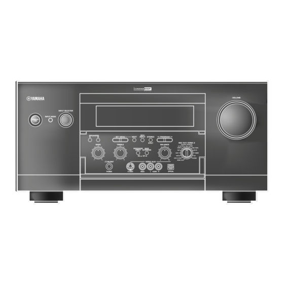
DSP-AZ1
INPUT SELECTOR
INPUT MODE
STANDBY
/ON
SPEAKERS
A
B
BASS
AV Amplifier
VOLUME
6CH
SET MENU
NEXT
INPUT
STEREO
PROGRAM
EFFECT
REC OUT/ZONE 2
TREBLE
BALANCE
SOURCE/REMOTE
D–TV/LD
DVD
PROCESSOR
BASS
CABLE
MD/TAPE
DIRECT
EXTENSION
SAT
CD–R
VCR 1
TUNER
ON
OFF
VCR 2
CD
VCR 3/DVR
PHONO
L
R
VIDEO AUX
SILENT
VIDEO AUX
PHONES
S VIDEO
VIDEO
L
AUDIO
R
OPTICAL
OWNER'S MANUAL
B
Advertisement
Chapters
Table of Contents

Related Manuals for Yamaha DSP-AZ1


Summary of Contents for Yamaha DSP-AZ1
- Page 1 DSP-AZ1 INPUT SELECTOR INPUT MODE STANDBY SPEAKERS SET MENU NEXT INPUT STEREO EFFECT BASS TREBLE PROCESSOR BASS DIRECT EXTENSION SILENT VIDEO AUX PHONES S VIDEO VIDEO AUDIO OWNER’S MANUAL AV Amplifier VOLUME PROGRAM REC OUT/ZONE 2 BALANCE SOURCE/REMOTE D–TV/LD CABLE MD/TAPE CD–R...
- Page 2 12 Only voltage specified on this unit must be used. Using this unit with a higher voltage than specified is dangerous and may cause fire, damage to this unit, and/or personal injury. YAMAHA will not be held responsible for any damage resulting from use of this unit with a voltage other than specified.
-
Page 3: Table Of Contents
Contents Contents INTRODUCTION Features ... 4 Controls and functions ... 6 PREPARATIONS Speaker system configurations ... 14 Speaker placement ... 16 Connections ... 18 On-screen displays (OSD) ... 33 Speaker mode settings ... 34 Speaker output levels ... 38 BASIC OPERATIONS Basic playback ... -
Page 4: Checking The Package Contents
CHECKING THE PACKAGE CONTENTS Check your package to make sure it has the following items. Remote control MACRO TRANSMIT RE–NAME CLEAR LEARN MACRO SYSTEM POWER STANDBY V–AUX TUNER PHONO CABLE MD/TAPE CD–R D–TV/LD VCR 1 VCR 2 VCR3/DVR 6CH INPUT TITLE ENTER SOURCE... -
Page 5: Introduction
Introduction Introduction This section describes the features of the DSP-AZ1, and its controls and functions. FEATURES ... 4 CONTROLS AND FUNCTIONS ... 6 Front panel ... 6 Remote control ... 8 Front panel display ... 11 Rear panel ... 12... -
Page 6: Features
Yamaha developed the Virtual CINEMA DSP algorithm which allows you to experience the virtual sound fields without surround speakers. This makes it possible for the DSP-AZ1 to produce a full surround sound catering to the number of speakers you have. The DSP-AZ1 also has a SILENT CINEMA DSP algorithm which is achieved by the crosstalk processing applying the precise Head Related Transfer Function. -
Page 7: Various Input And Output Jacks
I Various input and output jacks The DSP-AZ1 has various output jacks for audio and video signals as well as a digital recording output jack. Many input jacks are also available for connection to multiple audio-video sources. All the video inputs and outputs have S-video jacks in addition to standard composite video jacks for improved video picture quality. -
Page 8: Controls And Functions
Front panel INPUT SELECTOR INPUT MODE STANDBY STANDBY/ON Turns this unit on (On mode) and off (Standby mode). When you turn on this unit, you will hear a click and there will be a 4 to 5-second delay before this unit can reproduce sound. In Standby mode, this unit consumes a small amount of power so it can respond to the remote control. - Page 9 BASS EXTENSION ON/OFF When pushed in (ON), this feature boosts the bass frequency of the left and right main channels by +6 dB (60 Hz) while maintaining overall tonal balance. This boost is useful if you do not use a subwoofer.
-
Page 10: Remote Control
MOVIE /DTS THEATER 2 SUR. other components. Caution • You can operate the other components that are not Yamaha with this remote control after programming their remote control VOLUME functions (Learn) or setting the manufacturer code. 10KEY/DSP PARAMETER Selects the numeric button (10KEY) mode or DSP mode. You can... - Page 11 ON SCREEN Selects the On-Screen Display mode for your video monitor (see page 33). SLEEP Sets the sleep timer. TEST Selects the test mode. Remote control programming function buttons/ MACRO switch Programs new remote control functions, sets manufacturer codes, renames the input source names, or uses the Macro feature. Input section Selects the input source.
-
Page 12: Installing Batteries In The Remote Control
CONTROLS AND FUNCTIONS I Installing batteries in the remote control Open the battery compartment cover. Insert three supplied batteries (LR6) in the correct direction by aligning the + and – marks on the batteries with the polarity markings (+ and –) on the inside of the battery compartment. -
Page 13: Front Panel Display
Front panel display D–TV/LD MATRIX DISCRETE CABLE MD/TAPE DIGITAL CD–R PRO LOGIC VCR 1 TUNER 96kHz VCR 2 VCR3/DVR PHONO SLEEP V–AUX VIRTUAL Input source indicator Shows the current input source with the arrow-shaped cursor. indicator Lights up when you select a digital sound field program. indicator 96kHz 24bit... -
Page 14: Rear Panel
CONTROLS AND FUNCTIONS Rear panel DIGITAL AUDIO AUDIO PHONO (AC–3) COAXIAL TUNER CABLE (PLAY) CD–R CD–R (REC) OPTICAL TAPE (PLAY) MD/TAPE (REC) CD–R MAIN SURROUND OPTICAL D–TV WOOFER 6CH INPUT CENTER VIDEO VCR 3 /DVR DIGITAL ZONE 2 OUT DIGITAL OPTICAL/COAXIAL jacks See page 19 for detailed information. -
Page 15: Preparations
Preparations This section explains how to make preparations (speaker selection and placement, subwoofer usage, connection with other components, speaker mode setting, and speaker level adjustment) to fully use the DSP-AZ1. SPEAKER SYSTEM CONFIGURATIONS ... 14 SPEAKER PLACEMENT ... 16 CONNECTIONS ... 18 Before connecting components ... -
Page 16: Speaker System Configurations
SPEAKER SYSTEM CONFIGURATIONS The most complete speaker configuration consists of eight speakers: the left and right main speakers, a center speaker, the left and right rear speakers, the left and right front effect speakers, and a rear center speaker. If you do not use eight speakers, you can direct the signals for speakers that are not in your system to other speakers in your configuration. - Page 17 I 5-speaker configuration –standard 5.1 channel– This configuration does not express the height of the sound field as well as the 7- or 8-speaker configuration. However, it positions the dialogue sound as coming directly from the screen. For this speaker configuration, change SET MENU item “1F FRONT EFCT SP” to “NONE” and “1D REAR CT SP” to “NONE”. Speakers to be used •...
-
Page 18: Speaker Placement
Refer to the following diagram when you place the speakers. Caution • Use magnetically shielded speakers. If this type of speakers still creates the interference with a monitor, place the speakers away from the monitor. I Placing the main speakers TV or video monitor Main... - Page 19 I Placing the subwoofers Place the front subwoofer near the main speakers. Turn it slightly toward the center of the room to reduce wall reflections. If you use a rear subwoofer, place it behind the main listening position. The placement of the rear subwoofer is not critical because of the ultra low frequencies of the sound being reproduced.
-
Page 20: Connections
Before connecting components CAUTION Never connect this unit and other components to mains power until all connections between components have been completed. • Some components require different connection methods and have different jack names. Refer to the operation instructions for each component also. -
Page 21: Connecting Digital Jacks
When you connect other YAMAHA audio component (such as a CD player or changer, MD deck, or tape deck), connect to terminals with the same number labels. Yamaha applies this labelling system to all its products. -
Page 22: Connecting A Turntable
CONNECTIONS I Connecting a CD player The COAXIAL CD and OPTICAL CD jacks are available for a CD player which has coaxial or optical digital outputs. OPTICAL OUT CD Player COAXIAL OUT DIGITAL AUDIO AUDIO PHONO (AC–3) COAXIAL TUNER CABLE (PLAY) CD–R CD–R... -
Page 23: Connecting Video Components
Connecting video components Before you connect any components, disconnect the power supply to all the components you plan to connect including this unit and deter- mine which jacks are for the left and right channels and for input and output. After you finish all connections, check them again to make sure they are correct. -
Page 24: Connecting A Dvd Player
CONNECTIONS I Connecting a DVD player • Connect the left and right analog signal output jacks on your DVD player to the DVD L and R jacks. Connect the composite video signal output jack on your DVD player to the DVD VIDEO jack. •... - Page 25 I Connecting a digital TV/TV • Connect the left and right analog signal output jacks on your digital TV/TV to the D-TV/LD L and R jacks. Connect the composite video signal output jack on your digital TV/TV to the D-TV/LD VIDEO jack. •...
- Page 26 CONNECTIONS I Connecting a cable TV tuner • Connect the left and right analog signal output jacks on your cable TV tuner to the CABLE L and R jacks. Connect the composite video signal output jack on your cable TV tuner to the CABLE VIDEO jack. •...
- Page 27 I Connecting a satellite tuner • Connect the left and right analog signal output jacks on your satellite tuner to the SAT L and R jacks. Connect the composite video signal output jack on your satellite tuner to the SAT VIDEO jack. •...
-
Page 28: Connecting A Vcr
CONNECTIONS I Connecting a VCR • Connect the left and right audio signal output jacks on your VCR to the VCR 1 IN L and R jacks. Connect the left and right audio signal input jacks on your VCR to the VCR 1 OUT L and R jacks. Connect the composite video signal output jack on your VCR to the VCR 1 VIDEO IN jack. - Page 29 I Connecting an LD player • Connect the left and right audio signal output jacks on your LD player to the D-TV/LD L and R jacks. Connect the composite video signal output jack on your LD player to the D-TV/LD VIDEO jack. •...
- Page 30 CONNECTIONS I Connecting a video monitor • Connect the composite video signal input jack on your video monitor to MONITOR OUT 1 VIDEO jack. • If your video monitor has an S-video input or component video input, you can connect it to this unit. Connect the S-video signal input jack on your video monitor to the MONITOR OUT 1 S VIDEO jack or connect the component video signal input jacks on your video monitor to the COMPONENT VIDEO MONITOR OUT jacks.
-
Page 31: Connecting Speakers
Connecting speakers Front effect speakers Right Left Center speaker SPEAKERS FRONT REAR (SURROUND) CENTER REAR CENTER MAIN CAUTION SEE INSTRUCTION MANUAL FOR CORRECT SETTING. Right Left Right Left Main B speakers Main A speakers Good No good 10mm Speaker cable •... -
Page 32: Impedance Selector Switch
CONNECTIONS Subwoofer system Right PREOUT/MAIN IN FRONT CONTROL FRONT REAR (SURROUND) REMOTE 1 WOOFER SPLIT REMOTE 2 MONO CENTER REAR CTR RS– 232C CENTER MAIN CTRL MAIN 10mA +12V MAX. Subwoofer system Right rear speaker SPEAKERS FRONT REAR (SURROUND) CENTER REAR CENTER WARNING Do not change the IMPEDANCE SELECTOR switch setting... -
Page 33: Connecting Other Components
Connecting other components I Connecting external amplifiers If you want to increase the power output to the speakers, or want to use another amplifier, connect an external amplifier to the PREOUT/ MAIN IN terminals as follows. Caution • When an RCA pin-plug cable is connected to the PREOUT jack in order to output to the external amplifier, do not connect speakers to this unit. -
Page 34: Connecting An External Decoder
CONNECTIONS SUBWOOFER OUTPUT External decoder SURROUND OUTPUT CD–R MAIN SURROUND OPTICAL D–TV WOOFER 6CH INPUT VCR 3 /DVR DIGITAL VIDEO AUX S VIDEO VIDEO AUDIO OPTICAL OPTICAL OUT AUDIO OUT R AUDIO OUT L VIDEO OUT S VIDEO OUT Connecting the power supply cords To AC outlet MAINS IMPEDANCE SELECTOR... -
Page 35: On-Screen Displays (Osd)
You can display the operation information for this unit on a video monitor. If you display the SET MENU and DSP sound field program parameter settings on a screen, it is much easier to see the available options and parameters than it is by reading this information on the front panel display. -
Page 36: Speaker Mode Settings
This unit has seven SPEAKER SET items in the SET MENU that you must set according to the number of speakers in your configuration and their size. The following table summarizes these SPEAKER SET items, and shows the initial settings as well as other possible settings. If the initial settings are not appropriate for your speaker configuration, change the settings in the SET MENU. - Page 37 I 1A CENTER SP (center speaker mode) By adding a center speaker to your speaker configuration, this unit can provide good dialogue localization for many listeners and superior synchronization of sound and images. The OSD shows a large, small, or no center speaker depending on how you set this item. The initial setting is “LRG”.
- Page 38 SPEAKER MODE SETTINGS I 1C REAR L/R SP (rear speaker mode) The OSD shows large, small, or no rear speakers depending on how you set this item. The initial setting is “LRG”. LRG: Select the “LRG” setting if you have large left and right rear speakers or if you use a rear subwoofer. The entire range of rear channel signals is sent to the left and right rear speakers.
- Page 39 I 1E LFE/BASS OUT (bass output mode) LFE signals carry low frequency effects when this unit decodes DTS or Dolby Digital signals. Low frequency signals are defined as 90 Hz and below. The initial setting is “BOTH”. Select the “SW” (subwoofer) setting if you use a subwoofer. The LFE signals are directed to the subwoofer. MAIN: Select the “MAIN”...
-
Page 40: Speaker Output Levels
This section explains how to set the speaker output levels using the test tone generator. The “TEST DOLBY SUR.” is for balancing the output levels of the six speakers required for surround sound systems. The “TEST DSP” is for balancing the front effect speakers with the main speakers for the DSP sound field programs. -
Page 41: Test Dolby Sur
TEST DOLBY SUR. Select “TEST DOLBY SUR.” to match the output levels of the center, rear center and left and right rear speakers to the left and right main speakers. Press TEST on the remote control. “TEST DOLBY SUR.” appears on the video monitor and front panel display. -
Page 42: Test Dsp
SPEAKER OUTPUT LEVELS TEST DSP Select “TEST DSP” to match the output levels of the front effect speakers to the main speakers. Caution • You cannot enter the TEST DSP mode if “1F FRONT EFCT SP” is set to “NONE”. Press TEST repeatedly. -
Page 43: Basic Operations
Basic operations Basic operations This section explains the playback operation, DSP program selection and recording operation. BASIC PLAYBACK ... 42 Input modes and indications ... 44 Selecting a sound field program ... 46 BASIC RECORDING ... 50... -
Page 44: Basic Playback
MACRO TRANSMIT RE–NAME CLEAR LEARN MACRO SYSTEM POWER STANDBY V–AUX TUNER PHONO CABLE MD/TAPE CD–R D–TV/LD VCR 1 VCR 2 VCR3/DVR 6CH INPUT TITLE ENTER SOURCE DISPLAY MENU SOUND SELECT SEARCH CHAPTER POWER STOP PAUSE PLAY 10KEY HALL 1 HALL 2 CHURCH JAZZ CLUB ROCK... - Page 45 Adjust the volume to the desired output level. VOLUME VOLUME If desired, use BASS, TREBLE, BASS EXTENSION and BALANCE. These controls are only effective for sound from the main speakers. BASS TREBLE BASS EXTENSION Cautions • If the component connected to the VCR 1 OUT, VCR 2 OUT, VCR 3/DVR OUT, CD-R OUT and MD/TAPE OUT jacks is turned off, the reproduced sound may be distorted or the volume may be lowered for the characteristics of A/V...
-
Page 46: Input Modes And Indications
BASIC PLAYBACK Input modes and indications This unit comes with various input jacks. If your external compo- nent is connected to more than one type of input jack, you can set the priority of the input signal. Press INPUT MODE on the front panel or an input selector button (press it repeatedly) on the remote control to display or change the input mode. - Page 47 I Notes on playing DTS-CD/LDs • If the digital output data of the player has been processed in any way, you may not be able to perform DTS decoding even if you make a digital connection between this unit and the player. •...
-
Page 48: Selecting A Sound Field Program
BASIC PLAYBACK Selecting a sound field program You can enhance your listening experience by selecting a DSP program. There are 12 programs with sub-programs available with this unit. However the selection depends on the input signal format and not all the sub-programs are possible for all input signal formats. For details about each program, see pages 86 to 94. -
Page 49: Normal Stereo Reproduction
I Normal stereo reproduction Press STEREO/EFFECT to turn off the sound effect for normal stereo reproduction. STEREO STEREO EFFECT STEREO 3/2/LFE When “STEREO” is selected while Dolby Digital, DTS, or PCM signals are being played, the following information will be shown on the front panel display. - Page 50 BASIC PLAYBACK I Playing the Dolby Digital EX or DTS ES software Press EX/ES to turn on the Dolby Digital EX or DTS ES decoder to listen to the Dolby Digital EX and DTS ES software with a rear center speaker. The display changes AUTO ^ Discrete 6.1 ^ Matrix 6.1 ^ OFF each time the EX/ES is pressed.
- Page 51 I Virtual CINEMA DSP With the Virtual CINEMA DSP, you can enjoy all the DSP programs without rear speakers. It creates the virtual speakers to reproduce the natural sound field. The sound field processing is changed to the Virtual CINEMA DSP mode according to the selected DSP program by setting “1C REAR L/R SP”...
-
Page 52: Basic Recording
REC OUT/ZONE 2 allows you to record one source while viewing and/or listening to another source. INPUT MODE STANDBY Turn on the power to this unit and all connected components. Select the source component you want to record from by using REC OUT/ZONE 2. REC OUT/ZONE 2 SOURCE/REMOTE D–TV/LD... -
Page 53: Advanced Operation
Advanced operation Advanced operation This section explains SET MENU setting, remote control features and the other functions. SET MENU ITEMS ... 52 Operating the SET MENU ... 53 1 SPEAKER SET ... 54 2 LOW FREQ. TEST ... 54 3 HP TONE CTRL (headphone tone control) ... 55 4 CENTER GEQ (center graphic equalizer) ... -
Page 54: Set Menu Items
The SET MENU consists of eighteen items including the Speaker Set, Center Graphic Equalizer and Parameter Initialization features. Choose the appropriate item and adjust or select the values as necessary. Notes • You can adjust the items in the SET MENU while reproducing a source. •... -
Page 55: Operating The Set Menu
Operating the SET MENU 10KEY HALL 1 HALL 2 CHURCH JAZZ CLUB ROCK ENTER– CONCERT CONCERT CONCERT TAINMENT VIDEO 1 VIDEO 2 MOVIE MOVIE /DTS EX/ES THEATER THEATER 1 THEATER 2 SUR. CHP/INDEX A/B/C/D/E PRESET TV INPUT MUTE TV VOL VOLUME TV MUTE STEREO... -
Page 56: Speaker Set
SET MENU ITEMS 1 SPEAKER SET Set the speaker mode depending on your speaker system. See “SPEAKER MODE SETTINGS” on pages 34 to 37 for details about the setting items. 2 LOW FREQ. TEST Use this feature to adjust the output level of the subwoofer so it matches that of the other speakers in your configuration. I About the test tone Digital generator (wide band noise produced) -
Page 57: Hp Tone Ctrl (Headphone Tone Control)
3 HP TONE CTRL (headphone tone control) Use this feature to adjust the level of the bass and treble when you use your headphones. 4 CENTER GEQ (center graphic equalizer) Use this feature to adjust the built-in 5-band graphic equalizer so that the center speaker tonal quality matches that of the left and right main speakers. -
Page 58: Cinema Eq
SET MENU ITEMS 6 CINEMA EQ Use this feature to match the tonal quality of four groups of speakers: the main and center speaker group, the front effect speakers group, the rear speakers group, and the rear center speaker group. CINEMA-EQ consists of a high-shelving equalizer (HIGH) and a parametric equalizer (PEQ). -
Page 59: Input Rename
I 6B FRNT EFCT EQ (front effect equalizer) Use this feature to adjust the tonal quality of the front effect channels. I 6C REAR L/R EQ (rear L/R equalizer) Use this feature to adjust the tonal quality of the rear L/R channels. I 6D REAR CT EQ (rear center equalizer) Use this feature to adjust the tonal quality of the rear center channel. -
Page 60: O Assignment
SET MENU ITEMS 8 I/O ASSIGNMENT It is possible to assign jacks according to the component to be used if this unit’s COMPONENT VIDEO INPUT jack or DIGITAL INPUT/ OUTPUT jack settings (component names for jacks) differ from that component. This makes it possible to change the jack assignment and effectively connect more component. -
Page 61: Input Mode (Initial Input Mode)
9 INPUT MODE (initial input mode) Use this feature to designate the input mode for sources connected to the COAXIAL (OPTICAL) IN jacks when you turn on this unit (see page 44 for details about the input mode). 10 PARAMETER INI (parameter initialization) Use this feature to initialize the parameters for each DSP program within a DSP program group. -
Page 62: Dynamic Range
SET MENU ITEMS 12 DYNAMIC RANGE Use this feature to adjust the dynamic range. This setting is effective only when this unit decodes Dolby Digital signals. 13 SP DELAY Use this feature to adjust the delay of the center and the rear center channel sounds. This feature works when there is sound output from the center speakers, with a source like Dolby Digital or DTS, etc. -
Page 63: Audio Delay
I Setting by “msec” I Setting by “meters” I Setting by “feet” 14 AUDIO DELAY Use this feature to adjust the delay time of all channel sounds, when this unit decodes DTS or Dolby Digital signals. Adjusting “AUDIO DELAY” is especially important for matching the sounds to screen pictures. Control range: 0 –... -
Page 64: Display Set
SET MENU ITEMS 15 DISPLAY SET Use this feature to set the background and the location of the OSD, and the brightness of this unit’s front panel display. 16 MEMORY GUARD Use this feature to prevent accidental changes to DSP program parameter values and other settings on this unit. I DIMMER You can adjust the brightness of the front panel display. -
Page 65: Zone2 Set
17 ZONE2 SET Use this feature to change the volume control setting for audio output to ZONE 2 OUT. 18 6CH INPUT SET Use this feature to set the direction of the signals input into the center and subwoofer channels when the source component is connected to the 6CH INPUT jacks. -
Page 66: Remote Control Features
The remote control can operate not only the main unit but also other Yamaha and other manufactures’ audio and video components by using the Learning function and other manufactures’ code settings. The Macro feature also improves the operability of this unit allowing you to program a series of operations in sequence onto a single button. -
Page 67: Source Select
I Source select You can control another component independently from the input you selected by pressing an input selector button. Press SOURCE SELECT / to choose a component and set the remote control to be used for it. I About Zone2 When you make up a second audio-video room with this unit’s Zone2 system, you might want to use this remote control. -
Page 68: Setting The Manufacturer Code
You can control other components by setting a manufacturer code. A code can be set up in each component control area except for the OPTN area. The Yamaha code is factory preset for TUNER, MD/TAPE, CD-R, CD and DVD. TRANSMIT RE–NAME... - Page 69 Amplifier Library has the following three codes; YPC: Code to operate this unit DSP: Code to operate other Yamaha DSP amplifiers that cannot be operated with the YPC code Code to operate other manufacturers’ amplifier using this unit’s remote control...
-
Page 70: Programming A New Remote Control Function (Learn Feature)
REMOTE CONTROL FEATURES Programming a new remote control function (Learn feature) If you want to program functions not included in the basic operations covered by the manufacturer code, or a manufacturer code is not available, the following procedure needs to be performed. The possible programming area is the same as a component control area, so the buttons are programmable independently for each source component area. - Page 71 I Programmable buttons The shaded area shown below shows the buttons can be used for programming (Learn) for each component selected by the input selector button. MACRO TRANSMIT RE–NAME CLEAR LEARN MACRO SYSTEM POWER STANDBY V–AUX TUNER PHONO CABLE MD/TAPE CD–R D–TV/LD VCR 1...
-
Page 72: Each Component Control Area
Caution • “Yamaha” is factory-set in TUNER, CD, CD-R, MD, and DVD for their manufacturer code. It is necessary to change the manufacturer code if you would like to use the other manufacturers’ component. For other components than the ones listed above, you need to change the component category (Library) and then set the manufacturer code. - Page 73 DISC +/– (disc skip) Note • For a Yamaha CD player, if you press d or a once, it pauses. It stops if pressed again. * TV VOL +/–, TV INPUT, and TV MUTE function to operate your TV without switching the input if the manufacturer code is set in D-TV/LD or PHONO.
- Page 74 REMOTE CONTROL FEATURES I Operating a DVD player (DVD area) TRANSMIT RE–NAME CLEAR LEARN MACRO SYSTEM POWER STANDBY V–AUX TUNER CABLE MD/TAPE CD–R D–TV/LD VCR 1 VCR 2 VCR3/DVR TITLE ENTER SOURCE DISPLAY MENU SELECT SEARCH CHAPTER POWER STOP PAUSE 10KEY HALL 1 HALL 2...
- Page 75 I Operating a VCR (VCR 1, VCR 2 and VCR3/DVR areas) MACRO TRANSMIT RE–NAME CLEAR LEARN MACRO SYSTEM POWER STANDBY V–AUX TUNER PHONO CABLE MD/TAPE CD–R D–TV/LD VCR 1 VCR 2 VCR3/DVR 6CH INPUT TITLE ENTER SOURCE DISPLAY MENU SOUND SELECT SEARCH CHAPTER...
- Page 76 REMOTE CONTROL FEATURES I Operating a cable or satellite TV tuner (CABLE and SAT areas) TRANSMIT RE–NAME CLEAR LEARN MACRO SYSTEM POWER STANDBY V–AUX TUNER CABLE MD/TAPE CD–R D–TV/LD VCR 1 VCR 2 VCR3/DVR TITLE ENTER SOURCE DISPLAY MENU SELECT SEARCH CHAPTER POWER...
-
Page 77: Using The Macro Feature
VCR3/DVR In order to turn on some components (including YAMAHA components) connected to this unit, connect those components to the AC OUTLET(S) on the rear panel. (Power control may not be synchronized with this unit depending on the component. For details, please refer to the operation instruction for the connected component.) - Page 78 Programming a macro changes all macro contents. • A macro programming is used to transmit learning or setup (or YAMAHA preset) button signals of this remote control to a macro button. If necessary, set up the manufacturer code or program a function with the remote control for your component.
- Page 79 Cautions • “AGAIN” appears in the display window when a button other than the macro buttons is pressed. • If you want to change the source component, use SOURCE SELECT / or input selector buttons. When you use the input selector buttons, selecting the input is programmed as a macro step, whereas SOURCE SELECT / only changes the component.
-
Page 80: Changing The Source Name In The Display Window
REMOTE CONTROL FEATURES Changing the source name in the display window You can change the name that appears in the display window on the remote control if you want to use the different name from the original input selector button names. This is useful when different component is set in the input selector button. 2, 5 TRANSMIT RE–NAME... -
Page 81: Clearing A Learned Function Or Macro
Clearing a learned function or macro I To clear a learned function Press an input selector button to select the source component you want to clear the function. Press LEARN by using a ballpoint pen or similar object. “LEARN” and the selected component name appear alternately in the display window. -
Page 82: Clearing Learned Functions, Macros, Renamed Source Names, And Setup Manufacturer Codes
REMOTE CONTROL FEATURES Clearing learned functions, macros, renamed source names, and setup manufacturer codes You can reset the remote control to its factory setting by clearing the changed Libraries, programmed macros, set manufacturer codes and learned functions. 1, 3, 4 TRANSMIT RE–NAME CLEAR... -
Page 83: Adjusting The Levels Of The Effect Speakers
ADJUSTING THE LEVELS OF THE EFFECT SPEAKERS You can adjust the volume level of each effect speaker (center, right rear, rear center, left rear, front effect, and subwoofer) while listening to a music source. PARAMETER ON SCREEN LEVEL SET MENU SLEEP TEST PUSH... -
Page 84: Sleep Timer
Use this feature to automatically set this unit in the standby mode after the amount of time you have set. The sleep timer is useful when you are going to sleep while this unit is playing or recording a source. The sleep timer also automatically turns off the external components connected to AC OUTLET(S). -
Page 85: Zone 2
This unit • Some Yamaha models are able to connect directly to the RE- MOTE 1 OUT jacks of this unit. If you own these products, you may not need to use an infrared emitter. Up to six Yamaha components can be connected as shown. -
Page 86: Zone2
ZONE 2 Remote control in ZONE 2 In the second (Zone 2) room, the supplied remote control can be used as the Zone 2 remote control. You can select the input source and control the component which is located in the main room directly from the second room regardless of the listening condition in the main room. -
Page 87: Sound Field Programs
Sound field programs Sound field programs This section explains the sound field programs and its parameters. DIGITAL SOUND FIELD PROCESSING (DSP) ... 86 Understanding sound fields ... 86 Recreating a sound field ... 87 Illustration of the virtual sound sources and echo patterns ... 87 HI-FI DSP-SOUND FIELD PROGRAM ... -
Page 88: Digital Sound Field Processing (Dsp)
Yamaha sent teams of sound engineers all around the world to measure the sound reflections of famous concert halls and music venues, and collect detailed sound field information such as the direction, strength, range, and delay time of those reflections. -
Page 89: Recreating A Sound Field
The traditional stereo system that uses only two speakers is not capable of recreating a realistic sound field. Yamaha’s DSP requires four effect speakers to recreate sound fields based on the measured sound field data. The processor controls the strength and delay time of the signals output from the four effect speakers to localize the virtual sound sources in a full circle around the listener. -
Page 90: Hi-Fi Dsp-Sound Field Program
Caution • The sound field programs for this unit are designed based upon the detailed information that Yamaha sound engineers have collected by measuring the sound effect characteristics at the actual concert halls and music venues all over the world. Therefore you may find some difference in reverberation and volume of the sounds that are output from each of your speakers. -
Page 91: Concert Hall 1
CONCERT HALL 1 I Europe Hall A This is a large fan-shaped concert hall in Munich which has approximately 2500 seats. Almost the whole interior is made of wood. There is relatively little reflection from the walls, and sound spreads finely and beautifully. -
Page 92: Cinema-Dsp Sound Field Program
Dolby Digital, and DOLBY PRO LOGIC surround sound technologies with YAMAHA DSP sound field programs to provide the surround sound field. It recreates the most complete movie sound design in your audio room. In CINEMA-DSP sound field programs, Yamaha’s exclusive DSP processing is added to the front left, center, and right channels, so the listener can enjoy realistic dialogue, depth of sound, smooth transition between sound sources, and a surround sound field that goes beyond the screen. -
Page 93: Programs And Features
Programs and features If a Dolby Digital signal or DTS signal is input when the input mode is set to “AUTO”, the DSP program will be automatically switched to the Dolby Digital playback sound field or DTS playback sound field. Program ENTERTAINMENT Game... -
Page 94: Table Of Program Names For Each Input Format
CINEMA-DSP SOUND FIELD PROGRAM I Table of program names for each input format According to the input signal format, this unit automatically chooses the appropriate decoder and DSP sound field pattern. Input Program MOVIE THEATER 1 70 mm Spectacle MOVIE THEATER 2 70 mm Adventure 70 mm General DOLBY DIGITAL... -
Page 95: Movie Theater Programs
• 70mm Adventure • 70mm General These programs use Yamaha’s tri-field DSP process on each of the Dolby Digital or DTS signals for the front, left surround, and right surround channels. This processing enables this unit to reproduce the immense sound field and surround expression of a Dolby Digital or DTS equipped movie theater without sacrificing the clear separation of all channels. -
Page 96: Entertainment
CINEMA-DSP SOUND FIELD PROGRAM ENTERTAINMENT I Game This program adds a deep and spatial feeling to video game sounds and is also suitable for karaoke. CONCERT VIDEO 1 I Pop/Rock This program produces an enthusiastic atmosphere and lets you feel as if you are at an actual jazz or rock concert. -
Page 97: Sound Field Program Parameter Editing
SOUND FIELD PROGRAM PARAMETER EDITING You can enjoy good quality sound with the preset parameters. Although you do not have to change the initial settings, you can change some of the parameters to better suit the input source or your listening room. Changing parameter settings A/B/C/D/E PRESET... -
Page 98: Digital Sound Field Parameter Descriptions
DIGITAL SOUND FIELD PARAMETER DESCRIPTIONS You can adjust the values of certain digital sound field parameters so the sound fields are recreated accurately in your listening room. Not all of the following parameters are found in every program. I EFCT TRIM (Effect Trim) Function This parameter adjusts the level of all the effect sounds within a narrow range. - Page 99 I LIVENESS Function This parameter adjusts the reflectivity of the virtual walls in the hall by changing the rate at which the early reflections decay. Control range 0 – 10 Description The early reflections of a sound source decay much faster in a room with acoustically absorbent wall surfaces than in one which has highly reflective surfaces.
- Page 100 DIGITAL SOUND FIELD PARAMETER DESCRIPTIONS I S. DELAY (Surround Delay) Function This parameter adjusts the delay between the direct sound and the first reflection in the surround sound field. Control range 0 – 49 ms (The range depends on the signal format.) Description When Dolby Digital signals are decoded: the larger the parameter, the later the surround sound source begins.
- Page 101 I REV. TIME (Reverberation Time) Function This parameter adjusts the amount of time it takes for the dense, subsequent reverberation sound to decay by 60 dB (at 1 kHz). This changes the apparent size of the acoustic environment over an extremely wide range. Control range 1.0 –...
-
Page 102: Center Width
DIGITAL SOUND FIELD PARAMETER DESCRIPTIONS For 8ch Stereo I CT LEVEL (Center Level) I RL LEVEL (Rear Left Level) I RC LEVEL (Rear Center Level) I RR LEVEL (Rear Right Level) I FL LEVEL (Front Left Level) I FR LEVEL (Front Right Level) Function These parameters adjust the volume level for each channel in 8-channel stereo mode. -
Page 103: Appendix
Appendix Appendix TROUBLESHOOTING ... 102 CINEMA EQ FREQUENCY CHARACTERISTICS ... 105 REFERENCE CHART FOR THE INPUT AND OUTPUT JACKS ... 106 SPECIFICATIONS ... 107... -
Page 104: Troubleshooting
Refer to the chart below when this unit does not function properly. If the problem you are experiencing is not listed below or if the instruction below does not help, set this unit in the standby mode, disconnect the power cord, and contact the nearest authorized YAMAHA dealer or service center. - Page 105 Problem No sound from the effect speak- The input source is being played with normal stereo ers. reproduction. (“STEREO” is shown in the front panel display.) Digital signals that are over 96 kHz sampling frequency are input into this unit. No sound from the center speaker.
- Page 106 TROUBLESHOOTING Problem The sound field parameters and some other settings on this unit cannot be changed. This unit does not operate properly. “CHECK SP WIRES” appears on the front panel display. The sound is degraded when listening with headphones connected to a tape deck or CD player that is connected to this unit.
-
Page 107: Cinema Eq Frequency Characteristics
CINEMA EQ FREQUENCY CHARACTERISTICS I L, C, R preset value HIGH: FRQ 12.7 kHz/GAIN –3 dB PEQ: FRQ 12.7 kHz/GAIN –4 dB –3 –6 –9 I HIGH frequency FRQ 1.0 kHz/GAIN +6 – –9 dB –3 –6 –9 I PEQ frequency FRQ 1.0 kHz/GAIN +6 –... -
Page 108: Reference Chart For The Input And Output Jacks
REFERENCE CHART FOR THE INPUT AND OUTPUT JACKS ANALOG PHONO TUNER CD-R MD/TAPE D-TV/LD CABLE VCR 1 VCR 2 VCR 3/DVR VIDEO AUX 6CH INPUT MAIN SURROUND CENTER SUBWOOFER PREOUT/MAIN IN MAIN REAR (SURROUND) CENTER REAR CTR SUBWOOFER FRONT MONITOR OUT ZONE 2 OUT PHONES SPEAKERS... -
Page 109: Specifications
I Audio Section Minimum RMS Output Power per Channel MAIN L/R, CENTER, REAR L/R/C (20 Hz to 20 kHz, 0.015% THD, 8 Ω) ... 130 W FRONT L/R (1 kHz, 0.05% THD, 8 Ω) ... 45 W Maximum Power [for General and China models] MAIN L/R, CENTER, REAR L/R/C (1 kHz, 10% THD, 8 Ω) ... - Page 110 YAMAHA ELECTRONICS (UK) LTD. YAMAHA HOUSE, 200 RICKMANSWORTH ROAD WATFORD, HERTS WD1 7JS, ENGLAND YAMAHA SCANDINAVIA A.B. J A WETTERGRENS GATA 1, BOX 30053, 400 43 VÄSTRA FRÖLUNDA, SWEDEN YAMAHA MUSIC AUSTRALIA PTY, LTD. 17-33 MARKET ST., SOUTH MELBOURNE, 3205 VIC., AUSTRALIA...
Need help?
Do you have a question about the DSP-AZ1 and is the answer not in the manual?
Questions and answers