Table of Contents
Advertisement
POWER
PHONES
Natural Sound AV Receiver
Récepteur audiovisuel "Son Naturel"
CINEMA DSP
7ch
NATURAL SOUND
AV RECEIVER
RX–V2092
A/B/C/D/E
1
2
3
4
0
0
l
l
l
l
ON
OFF
2
2
2
2
3
3
3
4
4
4
4
5
5
5
5
A
B
BASS
TONE
EXTENSION
BYPASS
SPEAKERS
BASS
TREBLE
DIGITAL/
MOVIE
PRO LOGIC
ENHANCED
THEATER
ROCK
DISCO
CONCERT
JAZZ CLUB
VCR 2
VCR 1
VIDEO AUX
TAPE (MD)
TUNER
PHONO
5
6
7
8
SOURCE
0
DVD/LD
TAPE (MD)
l
l
2
2
TV/DBS
TUNER
FM/AM
DOWN TUNING
UP
DELAY/C/R
VCR 1
CD
3
3
3
/F/SWFR
MAN'L/AUTO FM
AUTO/MAN'L MONO
VCR 2
PHONO
4
4
L
5
5
R
VIDEO AUX
MEMORY
EDIT
TUNING
MODE
BALANCE
REC OUT
TV
EFFECT
SPORTS
STADIUM
CONCERT
CHURCH
HALL
VOLUME
l6
20
DVD/LD
l2
28
8
TV/DBS
40
4
2
CD
60
0
–dB
SET
MENU
S VIDEO
VIDEO
L AUDIO R
VIDEO AUX
OWNER'S MANUAL
MODE D'EMPLOI
Advertisement
Table of Contents

Related Manuals for Yamaha RX-V2092


Summary of Contents for Yamaha RX-V2092
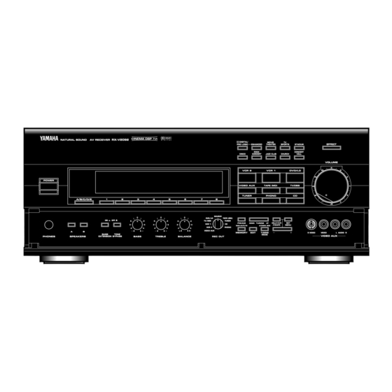
- Page 1 NATURAL SOUND AV RECEIVER POWER A/B/C/D/E PHONES SPEAKERS Natural Sound AV Receiver Récepteur audiovisuel “Son Naturel” CINEMA DSP RX–V2092 DIGITAL/ PRO LOGIC DISCO VCR 2 VIDEO AUX TUNER SOURCE DVD/LD TAPE (MD) TV/DBS TUNER FM/AM VCR 1 MAN’L/AUTO FM VCR 2 PHONO VIDEO AUX MEMORY...
-
Page 2: Safety Instructions
SAFETY INSTRUCTIONS Read Instructions – All the safety and operating instructions should be read CAUTION before the unit is operated. RISK OF ELECTRIC SHOCK DO NOT OPEN Retain Instructions – The safety and CAUTION: TO REDUCE THE RISK OF operating instructions should be retained ELECTRIC SHOCK, DO NOT REMOVE for future reference. - Page 3 This product, when installed as indicated in the instructions contained in this manual, meets FCC requirements. Modifications not expressly approved by Yamaha may void your authority, granted by the FCC, to use the product. 2. IMPORTANT : When connecting this product to accessories and/or another product use only high quality shielded cables.
- Page 4 Congratulations! You are the proud owner of a Yamaha Digital Sound Field Processing (DSP) System—an extremely sophisticated audio component. The DSP system takes full advantage of Yamaha’s undisputed leadership in the field of digital audio processing to bring you a whole new world of listening experiences.
-
Page 5: Precautions
YAMAHA will not be held responsible for any damage resulting from use of this unit with a voltage other than that which is specified. -
Page 6: Table Of Contents
SAFETY INSTRUCTIONS...Inside the cover PRECAUTIONS ...1 GETTING STARTED ...3 FEATURES ...5 SPEAKER SETUP...10 CONTROLS & THEIR FUNCTIONS ...13 FRONT PANEL...13 DISPLAY PANEL ...16 CONNECTIONS...18 REAR PANEL PARTS AND THEIR FUNCTIONS...18 REAR PANEL SWITCH AND CONTROL SETTINGS...22 GENERAL INSTRUCTIONS FOR CONNECTIONS ...22 CONNECTING AUDIO/VIDEO SOURCE EQUIPMENT TO THIS UNIT ...23 ANTENNA CONNECTIONS...27... -
Page 7: Getting Started
GETTING STARTED Unpacking If you haven’t already done so, carefully remove this unit and its accessories from the box and wrapping material.You should find the unit itself and the following accessories. Room 2 remote Remote control (for control unit the main room) AM loop antenna Antenna adapter (U.S.A. - Page 8 For the remote control unit for the main room only After you insert batteries (or you exchange batteries with new ones), press the RESET button before using the remote control unit. Remote control transmitter operation range Remote control sensor Within approximately 6 m (19.7 feet) Notes There should be no large obstacles between the remote control...
-
Page 9: Features
Extensive research into the exact nature of the sonic reflections that create the ambience of a large hall has made it possible for Yamaha engineers to bring you this same sound in your own listening room, so you’ll feel all the sound of a live concert. - Page 10 Dolby Pro Logic Surround This unit employs a Dolby Pro Logic Surround decoder similar to professional Dolby Stereo decoders used in many movie theaters. By using the Dolby Pro Logic Surround decoder, you can experience the dramatic realism and impact of Dolby Surround movie theater sound in your own home.
- Page 11 Yamaha DSP technology made it possible to present you with nearly the same sound experience as that of a large movie theater...
- Page 12 Dolby Pro Logic + 2 Digital Sound Fields Digital sound fields are created on the presence side and the rear surround side of the Dolby Pro Logic Surround-decoded sound field respectively. They create a wide acoustic environment and emphasize surround-effect in the room, letting you feel much presence as if you are watching a movie in a popular Dolby Stereo theater.
- Page 13 Video superimpose If you connect your video cassette recorder, LD player, video monitor, etc. to this unit, you can take advantage of this unit’s capability to display program titles and information for various setting changes and adjustments on your video monitor’s screen. This information will be superimposed over the video image.
-
Page 14: Speaker Setup
LFE (low frequency effect) sound with high fidelity when playing back a source with the Dolby Digital (AC-3) decoded. You may wish to choose the convenience of a Yamaha Active Servo Processing Subwoofer System, which has its own built-in power amplifier. - Page 15 Four Possible Types of Speaker System Configurations Recommended 4 Speaker System 5 Speaker System Simplest system. Good for Audio/Video sources. You can enjoy widely diffused sound By the use of center speaker, center by only adding two additional speaker sounds (dialog, vocals etc.) are units at the rear.
- Page 16 SPEAKERS. (To avoid interference, keep the speaker above or below the television monitor, or use a magnetically shielded speaker.) If using a SUBWOOFER, such as a Yamaha Active Servo Subwoofer System, the position of the speaker is not so critical because low bass tones are not highly directional.
-
Page 17: Controls & Their Functions
CONTROLS & THEIR FUNCTIONS FRONT PANEL NATURAL SOUND AV RECEIVER RX–V2092 POWER A/B/C/D/E BASS PHONES SPEAKERS EXTENSION BYPASS For control keys on the remote control unit, see pages 62 to 64. CINEMA DSP SOURCE DVD/LD TAPE (MD) TV/DBS TUNER VCR 1 VCR 2 PHONO VIDEO AUX... - Page 18 POWER Switch Turns this unit on and off. * When you press this switch to turn the power on, you will hear a click and a sound of the built-in fan rotating for a moment. Standby Indicator (Except U.S.A. and Canada models) While the power of this unit is on, pressing the (SYSTEM POWER) OFF key on the remote control unit switches this unit to the standby mode.
- Page 19 TONE BYPASS switch When this switch is pressed inward (ON), the input signal does not pass through the tone (BASS and TREBLE) control circuitry so that it is unaffected by the tone control circuitry. Use this switch to obtain pure sound and to check the tone control setting.
-
Page 20: Display Panel
Auxiliary Input Jacks (VIDEO AUX) Connect an auxiliary video or audio unit such as a camcorder to these jacks. If the connected video unit has a S video output terminal, connect it to the S VIDEO jack to obtain a high resolution picture. - Page 21 MEMORY Indicator When the MEMORY button is pressed, this indicator flashes for about 5 seconds. During this period, the displayed station can be programmed to the memory by using the A/B/C/D/E switch and the preset station number selector buttons. AUTO TUNING Indicator Lights up when this unit is in the automatic tuning mode.
-
Page 22: Connections
REAR PANEL PARTS AND THEIR FUNCTIONS Before you start making connections make sure all related electronic components are turned OFF. FREQUENCY AUDIO SIGNAL AUDIO SIGNAL STEP PHONO 50kHz 9kHz I00kHz I0kHz TAPE TAPE(MD) PCM/ DIGITAL IN (AC – 3 DIGITAL IN) UNBAL. - Page 23 Antenna Connection Terminals Connect the included indoor FM antenna to the FM ANT terminal and connect the included AM loop antenna to the AM ANT and GND terminals. To heighten safety and reduce interference, connect the GND terminal to a good earth ground. For improving reception quality, you can connect outdoor FM and/or AM antenna to these terminals (See pages 27 to 29 for details.)
- Page 24 ROOM 2 OUT Jacks These jacks output audio and video signals to the equipment in the second room. The input source selection is made using the Room 2 remote control unit. Refer to “CONNECTING AND CONTROLLING ROOM 2 EQUIPMENT” on page 38. REMOTE CONTROL IN and OUT Jacks The IN jack receives the commands from the Room 2 remote control unit.
- Page 25 REAR OUTPUT Jacks Rear-channel line output. Can be connected to input jacks of an external stereo power amplifier driving the rear speakers. MAIN SPEAKERS Terminals This unit is equipped with 2 sets of MAIN SPEAKERS terminals to allow you to connect 2 main speaker systems to this unit. When using this unit’s built-in main-channel amplifier, connect the main speakers here.
-
Page 26: Rear Panel Switch And Control Settings
REAR PANEL SWITCH AND CONTROL SETTINGS There are several switches and controls on the rear panel that you’ll have to check before operating your system, and it’s a good idea to do it before you connect cables. Locate the MAIN LEVEL slide switch (G) and FRONT MIX slide switch (F). -
Page 27: Connecting Audio/Video Source Equipment To This Unit
CONNECTING AUDIO/VIDEO SOURCE EQUIPMENT TO THIS UNIT BASIC CONNECTIONS If you have YAMAHA audio/video unit numbered as connect the output (or input) terminals of each unit to the same-numbered terminals of this unit. OUTPUT CD player LINE OUT LINE IN... - Page 28 CONNECTING TO DIGITAL (OPTICAL AND COAXIAL) JACKS If your LD (DVD) player, TV/satellite tuner, etc. are equipped with coaxial or optical digital audio signal output jacks, they can be connected to this unit’s COAXIAL and/or OPTICAL digital signal input jacks. To make a connection between optical digital audio signal jacks, remove the cover from each jack, and then connect them by using a commercially available optical fiber cable that conforms to...
- Page 29 COAXIAL jack take priority. In this case, switch off the RF demodulator to listen to CD sound surely. However, if your RF demodulator is the Yamaha model APD-1, you do not have to switch it off.
- Page 30 CONNECTING TO S VIDEO JACKS If your video cassette recorder, LD player, etc. and your monitor are equipped with “S” (high-resolution) video terminals, connect them to this unit’s S VIDEO jacks, and connect this unit’s S VIDEO MONITOR OUT jack to the “S” video input of your monitor.
-
Page 31: Antenna Connections
ANTENNA CONNECTIONS Each antenna should be connected to the designated terminals correctly, referring to the following figure. Both AM and FM indoor antennas are included with this unit. In general, these antennas will probably provide sufficient signal strength. Nevertheless, a properly installed outdoor antenna will give clearer reception than an indoor one. If you experience poor reception quality, an outdoor antenna may result in improvement. - Page 32 Connecting the indoor FM antenna Connect the included indoor antenna to the 75Ω UNBAL. FM ANT terminal. NOTE If you connect an outdoor FM antenna to this unit, do not connect the indoor FM antenna to this unit. Connecting the AM loop antenna 1.
- Page 33 Optional outdoor FM antenna Consult with your dealer or authorized service center about the best method of selecting and erecting an outdoor FM antenna. The choice of the feeder cable is also important. Flat ribbon- shaped twin-lead cable performs well electrically, and is cheaper and somewhat easier to handle when routing it through windows and around rooms.
-
Page 34: Connecting Speaker Systems
CONNECTING SPEAKER SYSTEMS Connect the SPEAKERS terminals to your speakers with wire of the proper gauge, cut as short as possible. If the connections are faulty, no sound will be heard from the speakers. Make sure that the polarity of the speaker wires is correct, that is, + and – markings are observed. - Page 35 CONNECTING THE MAIN SPEAKERS TO THIS UNIT One or two sets of MAIN speakers can be connected to this unit. If you use two sets of MAIN speakers, connect one set to the MAIN SPEAKERS A terminals, and connect another set to the B terminals.
- Page 36 CONNECTING THE FRONT EFFECT SPEAKERS, REAR SPEAKERS AND THE CENTER SPEAKER(S) TO THIS UNIT Connect the FRONT effect speakers to the FRONT EFFECT SPEAKERS terminals of this unit. If the FRONT effect speakers are not used, the FRONT MIX switch should be set to “ON”. Connect the REAR speakers to the REAR SPEAKERS terminals of this unit.
- Page 37 SUBWOOFER jack to the INPUT jack of the amplifier driving the other subwoofer, and then connect each subwoofer to the corresponding amplifier. REAR With some subwoofers, including the Yamaha Active Servo Processing Subwoofer System, the amplifier and subwoofer are in the same unit. COUPLER...
- Page 38 Switching the IMPEDANCE SELECTOR switch on the rear panel Select the position whose requirements your speaker system meets. Be sure to switch this only when the power of this unit is turned off. VOLTAGE SELECTOR AC OUTLETS SWITCHED IMPEDANCE SELECTOR CENTER C OR D: 4 MIN./ SPEAKER SET SPEAKER MODE C D: 4 MIN./ SPEAKER...
-
Page 39: Selecting The Output Modes Suitable For Your Speaker System
SELECTING THE OUTPUT MODES SUITABLE FOR YOUR SPEAKER SYSTEM This unit provides you the following four functions to determine the method of distributing output signals to speakers suitable for your audio system. When speaker connections are all completed, select a proper position on each function to make the best use of your speaker system. - Page 40 6. MAIN SPEAKER Choices: SMALL/LARGE Preset position: LARGE SMALL: Select this position if your main speakers do not have a high ability for bass reproduction. However, if your system does not include a subwoofer, do not select this position. In this position, low bass signals (below 90 Hz) at the main channels are output from the SUBWOOFER jacks (if the SWFR or BOTH position is selected on “7.
- Page 41 METHOD OF CHANGING SELECTIONS Operations should be made watching information on this unit’s display panel or the monitor screen. 1. Turn the power of this unit on. (If you want to display information on the monitor, turn the power of the monitor on.) Front panel POWER If you will use the remote control unit, set the TIME/LEVEL·SET...
-
Page 42: Connecting And Controlling Room 2 Equipment
Room 2 connections which will best meet your requirements. :Some Yamaha models are able to connect directly to this unit via the REMOTE CONTROL OUT jacks. If you own these products, the use of an infrared emitter may not be necessary. -
Page 43: Room 2 Remote Control Unit
POWER ON VOLUME ROOM 2 This remote control unit makes input source selections on this unit and controls Yamaha remote control-compatible CD player, tape deck, LD player and/or tuner connected to this unit for the second room independent of the input source selections for the main room. - Page 44 POWER ON and OFF keys (U.S.A. and Canada models) Pressing the POWER ON key turns the power of this unit on and pressing the OFF key turns the power off. (Except U.S.A. and Canada models) While the power is on, pressing the OFF key switches the unit from the power-on mode to the standby mode, and pressing the POWER ON key switches the unit from the standby mode to the power-on mode.
-
Page 45: Speaker Balance Adjustment
SPEAKER BALANCE ADJUSTMENT This operation uses an internal test-tone generator for balancing the levels of the main, center, rear and front effect speakers. The adjustment of each speaker output level should be done at your listening position with the remote control unit. Otherwise, the result may not be satisfactory. - Page 46 NOTE: If there is insufficient volume from the effect speakers, you may decrease the main speaker volume level by setting the MAIN LEVEL switch on the rear panel to “–10 dB”, and adjust each speaker level again. Volume controls on external power amplifiers may also be adjusted if necessary to achieve proper balance.
-
Page 47: Adjustments In The "Set Menu" Mode
ADJUSTMENTS IN THE “SET MENU” MODE The following eight types of functions maximize the performance of your system and expand your enjoyment for audio listening and video watching. 1. CENTER DELAY 2. DYNAMIC RANGE 3. LFE LEVEL 4. CENTER SPEAKER 5. - Page 48 DESCRIPTIONS OF THE FUNCTIONS 1. CENTER DELAY (Adjusting the delay of center sounds (dialog etc.)) Control range: 0 ms to 5 ms (in 1 ms step) Preset value: 0 ms This adjustment is effective only when the Dolby Digital (AC-3) is decoded and the signals of selected source encoded with the Dolby Digital (AC-3) contain center-channel signals.
- Page 49 3. LFE LEVEL (Adjusting the output level at the LFE (low frequency effect) channel) Control range: –20 dB to 0 dB (in 1 dB step) Preset value: 0 dB This adjustment is effective only when the Dolby Digital (AC-3) is decoded and the signals of selected source encoded with the Dolby Digital (AC-3) contain LFE signals.
-
Page 50: General Operation
GENERAL OPERATION PLAYING A SOURCE NOTE: If you will use the remote control unit, be sure to use it with the lid open. 1. Set the master VOLUME control to minimum. Front panel VOLUME –dB 2. Turn the power on. Front panel POWER 3. - Page 51 Notes on using the input selector buttons • Note that pressing on each input selector button selects the source which is connected to the corresponding input terminals on the rear panel. * To select the source connected to the VIDEO AUX terminals on the front panel, press VIDEO AUX.
-
Page 52: Recording A Source To Audio/Video Tape (Or Dubbing From A Tape To Another)
Notes on input mode selection • To play back a source with the Dolby Digital (AC-3) decoded, set the input mode to “AUTO”. • When you want to enjoy a source which has normal 2-channel signals with a Dolby Pro Logic Surround program, select the ANALOG mode. - Page 53 Regardless of the setting of input selector buttons, when you set the REC OUT selector to a position other than “SOURCE”, the source selected by the REC OUT selector can be recorded by other tape deck (MD recorder) and/or VCRs connected to this unit. While recording a source by setting the REC OUT selector to the position other than SOURCE as described above, the following operations can be made at the same time.
-
Page 54: Tuning Operations
TUNING OPERATIONS Normally, if station signals are strong and there is no interference, quick automatic-search tuning (AUTOMATIC TUNING) is possible. However, if signals of the station you want to select are weak, you must tune to it manually (MANUAL TUNING). AUTOMATIC TUNING 1. -
Page 55: Preset Tuning
MANUAL PRESET TUNING This unit can store station frequencies selected by tuning operation. With this function, you can recall any desired station by only selecting the preset station number where it is stored. Up to 40 stations (8 stations x 5 groups) can be stored. To store stations 1. -
Page 56: Automatic Preset Tuning
AUTOMATIC PRESET TUNING You can also make use of an automatic preset tuning function for FM stations only. By this function, this unit performs automatic tuning and stores FM stations with strong signals sequentially. Up to 40 stations are stored automatically in the same way as in the manual preset tuning method on page 51. -
Page 57: Exchanging Preset Stations
NOTES • You can replace a preset station by another FM or AM station manually by simply following the procedure of the section “To store stations” on page 51. • If the number of received stations is not enough to be stored up to E8, the search is finished automatically after searching all frequencies. -
Page 58: Selecting Sound Field Programs
SELECTING SOUND FIELD PROGRAMS This unit has 10 programs for digital sound field processing, 6 from actual acoustic environments from around the world, and 4 programs for Audio/Video sources including sources encoded with Dolby Pro Logic surround or Dolby Digital (AC-3). To select a DSP program Simply pressing a DSP program selector button on the front panel or a DSP program selector key on the remote control unit turns on... -
Page 59: Canceling The Effect Sound
CANCELING THE EFFECT SOUND The EFFECT switch on the front panel and the EFFECT ON/OFF key on the remote control unit make it simple to compare the normal stereo sound with the fully processed effect sound. To cancel the effect sound and monitor only the main sound, press the EFFECT ON/OFF key or the EFFECT switch. -
Page 60: Descriptions Of The Sound Field Programs
DESCRIPTIONS OF THE SOUND FIELD PROGRAMS The following list gives brief descriptions of the sound fields produced by each of the DSP programs. Keep in mind that most of these are precise digital recreations of actual acoustic environments. The data for them was recorded at the locations described using sophisticated sound field measurement equipment. - Page 61 3. MOVIE THEATER When the input signal is analog or PCM audio PRO LOGIC Speaker output: main, center, rear, front effect DIGITAL MOVIE THEATER When the input signal is Dolby Digital ( Speaker output: main, center, rear, front effect Ideal for reproducing video discs, video tapes and similar sources which are Dolby Surround encoded and bear the “DOLBY SURROUND”...
- Page 62 7. ROCK CONCERT When the input signal is analog or PCM audio ( Speaker output: main, rear, front effect When the input signal is Dolby Digital ( Speaker output: main, center, rear, front effect This program is ideally suited for rock music. You will experience a very dynamic or lively sound field.
-
Page 63: Adjusting Delay Time And Each Speaker Output Level
ADJUSTING DELAY TIME AND EACH SPEAKER OUTPUT LEVEL In using the digital sound field processor including the Dolby Pro Logic Decoder or the Dolby Digital (AC-3) Decoder, you can adjust delay time between the main sound and effect sound, and each speaker output level as you prefer. - Page 64 Adjusting delay time You can adjust the time difference between the beginning of the sound from the main speakers and the beginning of the effect sound from the rear or front effect speakers. The larger the value, the later the effect sound is generated. This adjustment can be made to all programs individually.
-
Page 65: Setting The Sleep Timer
SETTING THE SLEEP TIMER If you use the SLEEP timer of this unit, you can make this unit turn off automatically. When you are going to sleep while enjoying a broadcast or other desired input source, this timer function is helpful. -
Page 66: Remote Control Unit
If the CD player, tape deck, LD player etc. connected to this unit are YAMAHA components designed for remote control compatibility, then this remote control unit will also control various functions of each component. - Page 67 DSP program selector keys Selects a DSP program when the built-in digital sound field processor (including the Dolby Pro Logic Surround Decoder or the Dolby Digital (AC-3) Decoder) is on. TEST key Used when you make speaker balance adjustment to maximize the performance of your audio/video system including this unit.
-
Page 68: Learning New Control Functions (When The Lid Is Open)
If, for example, you store only Yamaha codes into this remote control unit, up to about 50 functions can be stored. Store new functions to the learnable-... - Page 69 A/B/C switch. 2. Press the key. The original factory settings of these keys are as follows. Preset with functions for controlling a Yamaha tape deck. Preset with functions for controlling a Yamaha CD player. (STOP is empty.) Preset with functions for controlling the built- in tuner.
- Page 70 Empty keys ( 1 These are empty keys. Each key can learn a function from another remote control unit. For example, the TV key is useful for storing the function of your TV’s power switch, and the VCR key can be used for your VCR’s power switch.
-
Page 71: Using Operation Control Keys (When The Lid Is Closed)
These keys are originally empty. If these keys have learned functions, pressing them executes those learned functions. TRANSMIT /LEARN CLEAR LEARN MACRO can easily operate Yamaha components including learned functions by using the OPERATION CONTROL keys. REC/PAUSE TAPE keys substitute for the keys of group numbered TUNER VCR 1... - Page 72 Pressing the “V-AUX” or “PHONO” input selector key has no effect on the OPERATION CONTROL keys. Examples of operations controlled by using the OPERATION CONTROL keys To operate a Yamaha CD player 1. Press the “CD” input selector key. 2. Use the OPERATION CONTROL keys. (They carry out the...
- Page 73 NOTES • If the OPERATION CONTROL keys substitute for keys which has no function (empty), no command is carried out. According to your plan, store functions from other remote control units into an empty area of those keys. (Refer to pages 73 to 74 for the learning method.) •...
-
Page 74: Macro Operations (When The Lid Is Closed)
MACRO OPERATIONS (When the lid is closed) “Macro” is a command which defines a sequence of several operations. The keys shown in the right illustrations (as “preset macro keys”) are also preset with macros, in addition to individual functions. Each macro key is preset so that simply pressing it alone will carry out several functions of other keys on this remote control unit sequentially. - Page 75 Preset macro keys and the key functions which they carry out sequentially are as follows. (Also, refer to the table on page 65.) Function of the key (and area) which operates when a macro key is pressed Macro key (Turning the power of this unit on) TAPE TUNER VCR 1...
- Page 76 NOTES • A key in which no function is stored will carry out no command. • If it occurs that this unit will not receive the second command because the internal operation of the first command takes a long time, set the MACRO switch to the “SLOW” position, or add no function or repeat the same command between the first command and the next command.
-
Page 77: Learning A New Function
LEARNING A NEW FUNCTION 1 Place this remote control unit and the other remote control unit so that they face each other. This remote control unit About 5–10 cm (2–4 in.) 2 Press the LEARN button using the point of a mechanical pencil etc. - Page 78 5 Press and hold the key (on the other remote control unit) which has the function you want to store. * When learning is finished, the TRANSMIT/LEARN indicator stops lighting and then begins flashing slowly. * If a signal is not successfully received, the TRANSMIT/LEARN indicator flashes rapidly and the mode prior to step 4 is restored.
-
Page 79: Making A New Macro
MAKING A NEW MACRO A new macro can be programmed onto any preset macro key in place of preset functions. (See page 70 to know what keys are preset macro keys.) You can make as many as 13 new macro keys. -
Page 80: Clearing Learned Functions
It is recommended to write down new key functions you stored on the provided user function stickers and paste them on the reverse side of the remote control unit or the reverse side of the remote control unit’s lid. Memory back-up All of the learned functions will be retained while you replace the batteries. - Page 81 To Clear All Learned Functions 1 Select the kind of key functions all of which you want to clear by using the MACRO switch on the side panel of the remote control unit. MACRO QUICK SLOW OFF: Select this position if you want to clear all of the learned functions except macros.
-
Page 82: Troubleshooting
General PROBLEM Power does not come on. The unit turns off suddenly soon after the power is turned on. Hum. No sound. No sound from the effect speakers. No sound from the front effect speakers. No sound from the center speaker. Poor bass reproduction. - Page 83 PROBLEM POSSIBLE CAUSE This unit will not operate properly. The internal microcomputer has been frozen by an external electric shock (lightning, excessive static electricity, etc.) or power supply with low voltage. A source cannot be recorded by a tape deck The source unit is connected to this unit between or VCR connected to this unit.
- Page 84 Tuner PROBLEM FM stereo reception is noisy. There is distortion and clear reception cannot be obtained even with a good FM antenna. A desired FM station cannot be tuned in with the automatic tuning method. Previously preset stations can no longer be tuned in.
-
Page 85: Specifications
AUDIO SECTION Minimum RMS Output Power Per Channel Main (20 Hz – 20 kHz 0.02% THD 8Ω) ... 100W+100W Center (20 Hz – 20 kHz 0.02% THD 8Ω) ... 100W Front Effect (1 kHz 0.05% THD 8Ω)...25W+25W Rear (20 Hz – 20 kHz 0.02% THD 8Ω) ... 100W+100W Dynamic Power Per Channel (by IHF Dynamic Headroom Measuring Method) [U.S.A., Canada and General models]... -
Page 86: Video Section
BASS EXTENSION (MAIN L/R) ... +6 dB (50 Hz) Filter Characteristics (Highcut Filter) SUBWOOFER (fc = 90 Hz) ... 24 dB/oct. VIDEO SECTION Video Signal Type [U.S.A. and Canada Models]...NTSC [Australia and Singapore models] ... PAL [General Model] ... NTSC/PAL Video Signal Level ... - Page 87 AM SECTION Tuning Range [U.S.A., Canada and General models] ...530 – 1,710 kHz [Australia and Singapore models] ...531 – 1,611 kHz Usable Sensitivity ...100 V/m Selectivity ...32 dB Signal-to-Noise Ratio...50 dB Image Response Ratio ...40 dB Spurious Response Ratio ...50 dB Harmonic Distortion (1 kHz)...0.3% AUDIO SECTION (TUNER) Output Level/Impedance...
- Page 88 YAMAHA ELECTRONICS (UK) LTD. YAMAHA HOUSE, 200 RICKMANSWORTH ROAD WATFORD, HERTS WD1 7JS, ENGLAND YAMAHA SCANDINAVIA A.B. J A WETTERGRENS GATA 1, BOX 30053, 400 43 VÄSTRA FRÖLUNDA, SWEDEN YAMAHA MUSIC AUSTRALIA PTY, LTD. 17-33 MARKET ST., SOUTH MELBOURNE, 3205 VIC., AUSTRALIA...