Toro Reelmaster 5410-D Operator's Manual
Traction unit
Hide thumbs
Also See for Reelmaster 5410-D:
- Operator's manual (92 pages) ,
- Service manual (662 pages) ,
- Operator's manual (64 pages)
Table of Contents
Advertisement
Register at www.Toro.com.
Original Instructions (EN)
Reelmaster
Model No. 03672—Serial No. 314000001 and Up
Model No. 03672A—Serial No. 314000001 and Up
Model No. 03687—Serial No. 314000001 and Up
Model No. 03687A—Serial No. 314000001 and Up
Form No. 3382-316 Rev B
®
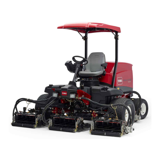
5410-D Traction Unit
*3382-316* B
Advertisement
Table of Contents

Related Manuals for Toro Reelmaster 5410-D


Summary of Contents for Toro Reelmaster 5410-D
- Page 1 ® 5410-D Traction Unit Model No. 03672—Serial No. 314000001 and Up Model No. 03672A—Serial No. 314000001 and Up Model No. 03687—Serial No. 314000001 and Up Model No. 03687A—Serial No. 314000001 and Up *3382-316* B Register at www.Toro.com. Original Instructions (EN)
- Page 2 Whenever you need service, genuine Toro parts, or additional information, contact an Authorized Service Dealer or Toro Customer Service and have the model © 2017—The Toro® Company Contact us at www.Toro.com. 8111 Lyndale Avenue South Printed in the USA.
-
Page 3: Table Of Contents
Safety ............... 4 Adjusting the Traction Drive for Neutral ..... 51 Safe Operating Practices........4 Adjusting the Rear Wheel Toe-in....... 51 Toro Riding Mower Safety........6 Cooling System Maintenance ......52 Engine Emission Certification ......7 Removing Debris from the Cooling Safety and Instructional Decals ...... -
Page 4: Safety
Preparation Safety • While mowing, always wear substantial footwear, long trousers, hard hat, safety glasses, and ear Improper use or maintenance by the operator protection. Long hair, loose clothing, or jewelry or owner can result in injury. To reduce the may get tangled in moving parts. - Page 5 Operation – before clearing blockages; – before checking, cleaning or working on the • Do not operate the engine in a confined space mower; where dangerous carbon monoxide fumes can collect. – after striking a foreign object or if an abnormal •...
-
Page 6: Toro Riding Mower Safety
The following list contains safety information specific object injuries. Do not resume mowing until the to Toro products or other safety information that you area is cleared. must know that is not included in the CEN, ISO, or ANSI standard. -
Page 7: Engine Emission Certification
Keep everyone away. • To ensure safety and accuracy, have an Authorized Toro Distributor check the maximum engine speed with a tachometer. • If major repairs are ever needed or if assistance is desired, contact an Authorized Toro Distributor. -
Page 8: Safety And Instructional Decals
Safety and Instructional Decals Safety decals and instructions are easily visible to the operator and are located near any area of potential danger. Replace any decal that is damaged or lost. decal93-7272 93-7272 1. Cutting/dismemberment—hazard, fan-stay away from moving parts. decal106-6755 106-6755 1. - Page 9 r:\decal110-8869 110-8869 1. Warning—read the Operator's Manual, do not operate this machine unless you are trained. 2. Thrown object hazard—keep bystanders a safe distance from the machine. 3. Tipping hazard—slow machine before turning, do not turn at high speeds; lower the cutting unit when driving down slopes;...
- Page 10 decal110-8924 110-8924 1. Warning—read the Operator's Manual and receive training. 2. Thrown object hazard—keep bystanders a safe distance from the machine. 3. Warning—do not park the machine on slopes; engage the parking brake, lower the cutting units, stop the engine and remove the ignition key before leaving the machine.
- Page 11 decal125-2927 125–2927 1. Read the Operator’s Manual for maintenance information.
-
Page 12: Setup
Setup Loose Parts Use the chart below to verify that all parts have been shipped. Procedure Description Qty. – No parts required Adjust the tire pressure. – No parts required Adjust the step height. – No parts required Adjust the control arm position. Front hose guide-R.H. -
Page 13: Adjusting The Tire Pressure
Raise or lower the step to the desired height and re-secure the brackets to the frame with the 2 bolts and nuts. Repeat the procedure on the other step. Adjusting the Tire Pressure No Parts Required Adjusting the Control Arm Procedure Position The tires are over-inflated for shipping. -
Page 14: Installing The Cutting Units
Installing the Cutting Units g003949 Parts needed for this procedure: Figure 5 1. Turf compensation spring 3. Spring tube Front hose guide-R.H. 2. Rod bracket Front hose guide-L.H. Remove the flange nut securing the spring Procedure tube bolt to the carrier frame tab (Figure Remove the assembly. - Page 15 g015160 Figure 8 1. Hose guide (#4 cutting unit 3. Nuts shown) 2. Rod bracket g019284 Figure 9 1. Hose guides (each must lean toward the center cutting unit) Note: When installing or removing the cutting units, make sure the hairpin cotter is installed in the spring rod hole next to the rod bracket.
- Page 16 g003979 Figure 12 1. Lift arm pivot shaft lynch pin and washer g003975 Figure 10 Insert the lift arm yoke onto the carrier frame shaft (Figure 11). 1. Snapper pin 2. Cap Insert the lift arm shaft into the lift arm and secure it with the washer and lynch pin For the front cutting units, slide a cutting unit (Figure...
-
Page 17: Adjusting The Turf Compensation Spring
Important: Make sure the reel motor hoses are not twisted, kinked or in the risk of being pinched. g003863 Figure 15 1. Turf compensation spring 3. Spring rod 2. Hair pin cotter 4. Hex nuts Tighten the hex nuts on the front end of the spring rod until the compressed length of the g004127 spring is 12.7 cm (5 inches) on Reelmaster... -
Page 18: Product Overview
Product Overview g003985 g003945 Figure 16 Figure 18 1. Cutting unit kickstand 1. Engine hood 5. Seat 6. Front cutting units 2. Operator's seat 3. Control arm 7. Rear cutting units Secure the kickstand to the chain bracket with the 4. -
Page 19: Traction Pedal
Traction Pedal Tilt Steering Pedal The traction pedal (Figure 20) controls the forward and To tilt the steering wheel towards you, press the foot reverse operation. Press the top of the pedal to move pedal (Figure 20) down, and pull the steering tower forward and the bottom to move rearward. -
Page 20: Headlight Switch
Lower Mow/Raise Control Lever Hydraulic Filter Restriction Indicator This lever (Figure 21) raises and lowers the cutting units and also starts and stops the cutterheads With the engine running at normal operating when the cutterheads are enabled in the mow mode. temperature, view the indicator (Figure 23), it should... - Page 21 Using the InfoCenter LCD Display InfoCenter Icon Description SERVICE DUE Indicates when scheduled service The InfoCenter LCD display shows information about should be performed your machine, such as the operating status, various diagnostics, and other information about the machine Engine rpm/status—indicates the engine speed (rpm) (Figure 25).
- Page 22 Contains a list of the recent Indicates when the cutting units are machine faults. Refer to being raised the Service Manual or your Authorized Toro Distributor for PIN code more information on the Faults menu and the information contained there.
- Page 23 0000 or 1234. If you changed the PIN code and forgot the Protected Menus Allows a person authorized by your company with the code, contact your Authorized Toro Distributor for PIN code to access protected assistance. menus. From the M...
- Page 24 To Set the Auto Idle • In the Settings Menu, scroll down to Auto Idle. • Press the right button to change the auto idle time between OFF, 8S, 10S, 15S, 20S, & 30S. To Set the Blade Count • In the Settings Menu, scroll down to Blade Count •...
-
Page 25: Specifications
Contact your Authorized Service Dealer or Distributor or go to CAUTION www.Toro.com for a list of all approved attachments and accessories. If you leave the key in the ignition switch, someone could accidently start the engine and seriously injure you or other bystanders. -
Page 26: Filling The Fuel Tank
Filling the Fuel Tank WARNING Fuel is harmful or fatal if swallowed. Long-term exposure to vapors can cause DANGER serious injury and illness. In certain conditions, fuel is extremely • Avoid prolonged breathing of vapors. flammable and highly explosive. A fire or explosion from fuel can burn you and others •... -
Page 27: Checking The Cooling System
• Contact your Authorized Toro Distributor if you wish for more information on biodiesel. • Use a rag when opening the radiator cap, and open the cap slowly to allow steam to Fuel Tank Capacity escape. -
Page 28: Checking The Hydraulic Fluid
30). Remove the cap 19 L (5 US gallon) pails or 208 L (55 US gallon) drums. See the Parts Catalog or your Toro Distributor for part numbers.) from the filler neck. Alternate fluids: If the Toro fluid is not available, other fluids may be used provided they meet all the following material properties and industry specifications. -
Page 29: Check The Torque Of The Wheel Nuts
Check the Torque of the Setting the Reel Speed Wheel Nuts To achieve a consistent, high quality-of-cut and a uniform after cut appearance, it is important that you Torque the wheel nuts to 94 to 122 N-m (70 to 90 ft-lb). set the reel speed to the proper setting. -
Page 30: Diesel Particulate Filter Regeneration
Diesel Particulate Filter Important: Minimize the amount of time that you idle the engine or operate the engine at low-engine Regeneration speed to help reduce the accumulation of soot in the soot filter. The diesel particulate filter (DPF) is part of the exhaust system. - Page 31 DPF Ash Accumulation • When enough ash accumulates, the engine computer sends information to the InfoCenter in • The lighter ash is discharged through the exhaust the form of a system advisory or an engine fault to system; the heavier ash collects in the soot filter. indicate the accumulation of ash in the DPF.
- Page 32 Types of Diesel Particulate Filter Regeneration Types of diesel particulate filter regeneration that are performed while the machine is operating: Type of Regeneration Conditions for DPF regeneration DPF description of operation Passive Occurs during normal operation of the machine at The InfoCenter does not display an icon indicating high-engine speed or high-engine load passive regeneration.
- Page 33 DPF is already in need of a parked When the recovery-regeneration icon regeneration displayed in the InfoCenter, a recovery regeneration is requested. Contact your Authorized Toro Distributor to have a service technician perform the recovery regeneration. • A recovery regeneration requires up to 4 hours to complete.
- Page 34 Reset Regeneration Parked Regeneration g214713 g214711 Figure 39 Figure 38 Parked-regeneration request icon Assist/reset-regeneration icon • The parked-regeneration requested icon displays • The assist/reset-regeneration icon displays in the in the InfoCenter (Figure 39). InfoCenter (Figure 38). • If a parked regeneration is needed, the InfoCenter •...
- Page 35 Engage the parking brake. Set the throttle to the low I position. Performing a Parked Regeneration Note: For instructions on unlocking protected menus, refer to Accessing Protected Menus (page 23). Access the protected menu and unlock the protected settings submenu (Figure 41);...
- Page 36 g211986 g212405 Figure 45 Figure 47 Move the throttle control to and press LOW IDLE The “Waiting on ” message displays the center button (Figure 46). (Figure 48). g212372 g212406 Figure 46 Figure 48 The following messages display as the parked The computer determines whether the regeneration process begins: regeneration runs.
- Page 37 The engine is cold—wait. The engine is warm—wait. The engine hot—regeneration in progress (percent complete). The parked regeneration is complete when the “Regen Complete” message displays in the InfoCenter. Press the left button to exit to the home screen (Figure 51).
-
Page 38: Adjusting The Lift Arm Counterbalance
• You need a distributor technician to perform the recovery regeneration process; contact your The lift arm switch is located underneath the Authorized Toro Distributor. hydraulic tank behind the front right lift arm (Figure 54). Adjusting the Lift Arm... -
Page 39: Jacking Points
Tie Downs • Front—the hole in the rectangular pad, under the axle tube, inside each front tire (Figure 57). g003995 Figure 55 1. Bypass valve Close the bypass valve before starting the engine. However, do not exceed 7-11 N-m. (5-8 ft.-lb) torque to close the valve. -
Page 40: Understanding The Diagnostic Light
Understanding the Verifying the Interlock Switch Function Diagnostic Light Park the machine on a level surface, lower the The machine is equipped with a diagnostic light which cutting units, stop the engine, and engage the indicates if the machine detects a malfunction. The parking brake. -
Page 41: Hydraulic Valve Solenoid Functions
Hydraulic Valve Solenoid Functions Use the list below to identify and describe the different functions of the solenoids in the hydraulic manifold. Each solenoid must be energized to allow function to occur. Solenoid Function Front reel circuit Rear reel circuit SVRV Lift/lower cutting units Lift/lower front cutting units... -
Page 42: Maintenance
Maintenance Note: Determine the left and right sides of the machine from the normal operating position. Recommended Maintenance Schedule(s) Maintenance Service Maintenance Procedure Interval • Torque the wheel lug nuts to 94 to 122 N-m (70 to 90 ft-lb). After the first hour •... -
Page 43: Daily Maintenance Checklist
Refer to your Engine Operator's Manual for additional maintenance procedures. Note: Looking for an Electrical Schematic or Hydraulic Schematic for your machine? Download a free copy of the schematic by visiting www.Toro.com and searching for your machine from the Manuals link on the home page. -
Page 44: Service Interval Chart
Service Interval Chart decal125-2927 Figure 60 CAUTION If you leave the key in the ignition switch, someone could accidently start the engine and seriously injure you or other bystanders. Remove the key from the ignition before you do any maintenance. Lubrication Greasing the Bearings and Bushings... - Page 45 • • Lift arm pivots (1 each) (Figure Axle steering pivot (1) (Figure • Cutting unit carrier frame and pivot (2 each) (Figure g004169 Figure 66 • Steering cylinder ball joints (2) (Figure g003960 Figure 63 • Lift arm pivot shaft (1 each) (Figure g003966 Figure 67...
-
Page 46: Engine Maintenance
Remove and replace the filter (Figure 70). Toro Premium Engine Oil is available from your Authorized Toro Distributor in either 15W-40 or Cleaning of the used element is not 10W-30 viscosity grades. See the parts catalog for recommended due to the possibility of damage part numbers. -
Page 47: Changing The Engine Oil And Filter
Checking the Engine-Oil Level Crankcase Oil Capacity Service Interval: Before each use or daily 5.2 L (5.5 US qt) with the filter Important: Check the engine oil daily. If the Changing the Engine Oil and Filter engine-oil level is above the Full mark on the dipstick, the engine oil may be diluted with fuel;... -
Page 48: Servicing The Diesel-Oxidation Catalyst (Doc) And The Soot Filter
DPF. Figure 75 Refer to your Authorized Toro Distributor for 1. Water separator filter canister diesel-oxidation catalyst and the soot filter replacement parts or service. Clean the area where the filter canister mounts. -
Page 49: Servicing The Engine Fuel Filter
Checking the Fuel Lines Lubricate the gasket on the filter canister with clean oil. and Connections Install the filter canister by hand until the gasket contacts mounting surface, then rotate it an Check the fuel lines and connections every 400 hours additional 1/2 turn. -
Page 50: Electrical System Maintenance
Fuses Electrical System Maintenance There are 8 fuses in the electrical system. The fuse block (Figure 77) is located behind the control arm access panel. Important: Before welding on the machine, disconnect both cables from the battery, both wire harness plugs from the electronic control module, and the terminal connector from the alternator to prevent damage to the electrical system. -
Page 51: Drive System Maintenance
Drive System Start the engine and rotate the cam hex in either direction until the wheels cease rotation. Maintenance Tighten the locknut to secure the adjustment. Stop the engine. Remove the jack stands and Adjusting the Traction lower the machine to the shop floor. Test drive the machine to make sure it does not Drive for Neutral creep. -
Page 52: Cooling System Maintenance
Cooling System Maintenance Removing Debris from the Cooling System Remove debris from the screen and radiator/oil cooler daily (clean more frequently in dirty conditions). Turn the engine off and remove the key from the ignition switch. Thoroughly clean all debris out of the engine area. -
Page 53: Brake Maintenance
Brake Maintenance Adjusting the Parking Brake Adjusting the Service If the parking brake fails to engage, an adjustment to the brake pawl is required. Brakes Loosen the 2 screws securing the parking brake Adjust the service brakes when there is more than pawl to the frame (Figure 84). -
Page 54: Belt Maintenance
If fluid becomes Check the condition and tension of the belt (Figure contaminated, contact your local Toro distributor 85) after every 100 operating hours. because the system must be flushed. Contaminated Proper tension will allow 10 mm (3/8 inch) fluid looks milky or black when compared to clean oil. -
Page 55: Replacing The Hydraulic Filters
Check the level of the hydraulic fluid and add enough to raise level to the Full mark on the dipstick. Important: Do not over-fill. Replacing the Hydraulic Filters The hydraulic system is equipped with a service interval indicator (Figure 87). With the engine running at operating temperature, view the indicator, it should be in the Green zone. -
Page 56: Hydraulic System Test Ports
Use the hydraulic system test ports to test the to assist in troubleshooting the lift circuit. pressure in the hydraulic circuits. Contact your local Toro distributor for assistance. Use the test ports on the front hydraulic tubes (Figure 90) to assist in troubleshooting the traction circuit. -
Page 57: Cutting Unit System Maintenance
Cutting Unit System Apply lapping compound with a long handle brush. Never use a short handled brush. Maintenance If the reels stall or become erratic while backlapping, select a higher reel speed setting until the speed stabilizes, then return the reel Backlapping the Cutting speed to your desired speed. -
Page 58: Storage
Clean the battery, terminals, and posts with a wire brush and baking soda solution. Coat the cable terminals and battery posts with Grafo 112X skin-over grease (Toro Part No. 505-47) or petroleum jelly to prevent corrosion. Slowly recharge the battery every 60 days for 24 hours to prevent lead sulfation of the battery. - Page 59 Notes:...
-
Page 60: The Toro Total Coverage Guarantee
Countries Other than the United States or Canada Customers who have purchased Toro products exported from the United States or Canada should contact their Toro Distributor (Dealer) to obtain guarantee policies for your country, province, or state. If for any reason you are dissatisfied with your Distributor's service or have difficulty obtaining guarantee information, contact the Toro importer.