Envertech EVT300 Quick Installation Manual
Hide thumbs
Also See for EVT300:
- User manual (22 pages) ,
- Quick installation manual (2 pages) ,
- User manual (11 pages)
Advertisement
Quick Links
Envertech EVT300 & EVT360 + EVB300 Quick Installation Guide
Please read and follow the safety and installation
instructions below. You can find and download the
instructions or other technical documents on our
website:
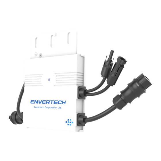
Components
Microinverter
Monitoring Device
EVT300 & EVT360
EnverBridge
PV
60-cell / 72-cell module
Module
AC
To connect the AC side
Extension
to the grid.
Cable
Three-wire cable:
(Optional)
AWG12 or above.
AC End
To seal the end of
Cap
unused AC cable.
Note: EnverView App version should be 2.6 and above and EVB300 firmware
version should be EVB300-E-N-001-14 and above.
Envertech EVT300 & EVT360 Microinverter Installation
Installation could only be implemented when the system is
disconnected from the grid, and the solar panel has been covered
or disconnected.
1.
Mount microinverters onto the rack
Mark out the estimated center of each PV module on the rack to facilitate locating
microinverters..
Mount all microinvertes under modules to avoid rain and sun, with the trademark
facing downward.
Please make sure that there are less than 20 units of EVT300, or 16 units of
EVT360 in each branch(12AWG).
2.
Grounding
Microinverters and modules must be connected to the grounding conductor in
accordance with national standards.
Fix the grounding wire with screws to the microinverter's grounding hole, so that
the grounding of microinverters can be realized.
3.
Connect microinverter AC cables serially
Connect the AC connectors on both sides of microinverters in a hand-in-hand way.
4.
Fastern AC cables
Fasten AC cables and grounding cables to the rack with cable ties.
www.envertec.com
.
Monitoring APP
EnverView
5.
Seal the unused connector of AC cable
Insert the end cap directly into the connector on the unused end, and check if it is
inserted in place.
6.
Connect AC cable to the junction box
Connect AC cable to the input of the junction box.
7.
Mount EnverBridge
Take out the power cord and connect it to the EVB300, Screw on the antenna. Wait 3
minutes till the EVB300 green light blink, you can start the operation after booting
EVB300.
1)
Installation
Option 1: Ethernet Mode
Fix EVB300 at proper position in or
close to the distribution box;
2. Run the RJ45 cable and connect the
EVB300 to your router;
3. Put the EVB300 plug into the socket.
Option 2: Wireless mode
Fix EVB300 at proper position in or
close to the distribution box within the
range Wi-Fi signal.
Turn off the air switch and connect
EVB300' s power cable to the air switch.
2)
Wi-Fi configuration setting
a)
Connect network whose name is as same as your monitor's SN in your
cellphone.
b)
Open EnverView and click Wi-Fi Setting.
Advertisement

Related Manuals for Envertech EVT300


Summary of Contents for Envertech EVT300
- Page 1 Wi-Fi configuration setting Connect network whose name is as same as your monitor’s SN in your Please make sure that there are less than 20 units of EVT300, or 16 units of cellphone. EVT360 in each branch(12AWG). Grounding Microinverters and modules must be connected to the grounding conductor in accordance with national standards.
- Page 2 Connect one side of the extension cable to the junction box; Please ensure that both EVB300 and your phone are in same router network. There is one serial number in EVT300 or EVT360, please make sure both serial numbers are added.
- Page 3 Or you can scan the bar code. length 780 mm length 1025 mm length 1025 mm length 245 mm Step 3: Click confirm to finish Adding MI. length 780 mm length 1025 mm length 1025 mm length 245 mm Three Phase installation length 780 mm length 1025 mm length 1025 mm...
Need help?
Do you have a question about the EVT300 and is the answer not in the manual?
Questions and answers