Table of Contents
Advertisement
Quick Links
Advertisement
Table of Contents

Related Manuals for DeLonghi NESCAFE Dolce Gusto EDG 305


Summary of Contents for DeLonghi NESCAFE Dolce Gusto EDG 305
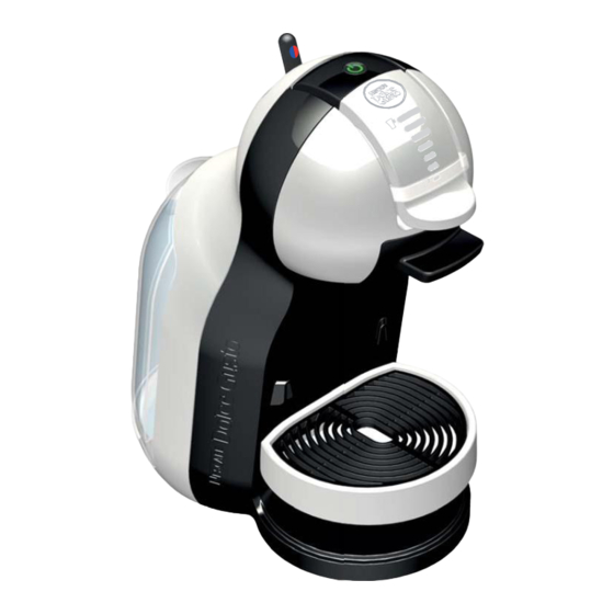
- Page 1 S E R V I C E M A N U A L B E V E R A G E C E N T E R EDG 305 Version 1.0 en...
-
Page 2: Table Of Contents
C O N T E N T S Main components ....................5 Overview of external parts.................... 5 Overview of internal parts..................... 6 Overview of rating plates .................... 7 De Longhi rating plate ....................7 Krups rating plate ..................... 8 Water circuit........................ 9 Technical data ...................... 10 Operating ........................ 12 Machine status ...................... 12 Preparation, first use .................... 13 Preparing a beverage .................... 15 Economy mode (auto shutoff function) .............. - Page 3 Final testing ......................49 Test equipment......................49 Heating up time ......................50 Flow rate (at 8 bar) / water temperature..............50 Maximal pressure / leakage check................52 Final inspections ....................53 General ........................53 Safety instructions....................... 54 Protective earthing (PE) resistance test..............54 Insulation resistance test.....................
- Page 4 P R E F A C E The purpose of this Service Manual is to provide the service personnel with all neces sary information with regards to correct handling, maintenance and repair of the Mini Me beverage center. This Service Manual should be used by the technicians as a valuable aid to guarantee the permanent readiness for use of the machine. In order to take full advantage of all the functions, it is absolutely necessary to follow the instructions in this manual. For a quick information access, this service manual is also available in the internet as a PDF or HTML file. The required utility software to read PDF files (Adobe Reader®) for PCs and MAC computers can be downloaded (under http://www.adobe.com) for free please click the logo: 4 Service manual ...
-
Page 5: Main Components
M A I N C O M P O N E N T S M A I N C O M P O N E N T S Overview of external parts 1. Water tank 6. Volume selector 2. Selection lever 7. Locking handle 3. Cold 8. -
Page 6: Overview Of Internal Parts
M A I N C O M P O N E N T S Overview of internal parts 1. Power button 9. NTC temperature sensor 2. Locking lever 10. Thermo fuses (2x) 3. Needle plate 11. Electronic main board 4. Hotcold selection lever 12. Hot water pressure hose 5. Water tank connector 13. Cold water pressure hose 6. Flow meter 14. Reed sensor 7. -
Page 7: Overview Of Rating Plates
M A I N C O M P O N E N T S Overview of rating plates De Longhi rating plate The rating plate • can be found on the underside of the machine, • carries the following information: 7 Service manual ... -
Page 8: Water Circuit
M A I N C O M P O N E N T S Water circuit 1. Water tank with valve 6. Selection lever 2. Filter and connector 7. Fconnector 3. Flow meter 8. Capsule holder 4. Pump 9. Needle plate 5. Thermoblock 10. Needle 9 Service manual ... -
Page 9: Technical Data
M A I N C O M P O N E N T S Technical data Mains voltage Europe (UK, CH, DE, AT, FR, ES, PT, IT, NL, LU, BE, NO, SE, FI, DK, GR, CZ, SK, PL, HU, RU, UA, LT, LV, EE, BG, RO, SI, BiH, SRB, HR) ... 230 V / 50 Hz USA / Canada ...................120 V / 60 Hz Hong Kong ..................220 240 V / 50 Hz Mexico ....................127 V / 50/60 Hz Chile ......................220 V / 50 Hz Japan.....................100V / 50/60 Hz Approvals ..................CE, UL, CUL, JET Power consumption ................max. 1’500 W Ratings (approx.) Preheating ......................10.0 Wh 1 small cup (40 ml, Espresso) ... - Page 10 M A I N C O M P O N E N T S Various data Preheating time..................approx. 40 sec. Pump pressure max................. 13.5 ± 1.5 bar Noise ......................max. 65 dB(A) Dimensions [mm] Power cord length ..................approx. 1 m Weight of machine(without water) ................. 2.5 kg Distance from drip grid to coffee outlet [mm] Espresso .......................80 mm Mug ........................125 mm Tall glass ......................155 mm Higher cup......................180 mm 11 Service manual ...
-
Page 11: Operating
O P E R A T I N G O P E R A T I N G Machine status After switching on, an automatic selftest is performed to check if the NTC is connected, NTC is not short circuited, the thermoblock reaches the working temperature in about 40 seconds, the selection lever is in middle position. Operating modes and detected failures are indicated by LED signals of the power button as listed in the following table: Operating modes Power button LED signals Economy mode / Off — Heating up / selftest red, blinking, approx. 40 sec. Ready green, steady After beverage preparation red, blinking, approx. 10 sec. ... -
Page 12: Preparation, First Use
O P E R A T I N G Preparation, first use The new machine has to be rinsed properly before first use according to the following sequence: Open locking handle and insert 1. Rinse water tank at first. Then fill 3. empty capsule holder. Close locking water tank up to max. level with fresh handle drinking water. 4. Place empty jug under outlet. 2. Insert water tank into machine. 5. Make sure that the selection lever is 7. Switch machine on. While machine is in "STOP" position. heating up, power button starts 6. Connect power plug to mains power blinking red. socket. 8. After approx. 40 seconds, power button lights steady green and machine is ready. 9. Set the volume selector to maximum 11. - Page 13 O P E R A T I N G 13. Move lever to the right to start 14. Wait until the lever comes back to the rinsing. middle and extraction stops. Empty and clean the jug. 15. Empty and clean the water tank with 17. Insert water tank into machine. clean cleaning tools. 18. Place drip grid on drip tray and insert 16. Fill tank with fresh drinking water up at the desired position. to maximum level. 14 Service manual ...
-
Page 14: Preparing A Beverage
O P E R A T I N G Preparing a beverage 1. Switch machine on. 4. Adjust drip tray position according to 2. While machine is heating up, power the chosen beverage. Place cup on drip tray button starts blinking red. 5. 3. After approx. 40 seconds, power button lights steady green and machine is ready. 6. Open locking handle and pull out 9. Set the beverage volume with the capsule holder. volume selector. Follow the recom 7. Insert capsule in capsule holder and mendation on the capsule or set put it back into the machine. volume to your own taste. 8. Close locking handle. 10. Move lever to the right for hot bever 14. When preparation is finished, power ages, to the left for cold beverages. ... -
Page 15: Economy Mode (Auto Shutoff Function)
O P E R A T I N G 16. Take cup from drip tray. 18. Pull out capsule holder and remove 17. Open the locking handle. used capsule. 19. Put used capsule in capsule bin. 20. Rinse both sides of the capsule holder with water from both sides and dry. 21. Insert capsule holder into machine. Enjoy your beverage! Economy mode (auto shutoff function) After 5 minutes without operation, the machine switches itself OFF automatically. This feature helps to save electricity by reducing the amount of power the machine draws while it is not in use and helps to protect the life of the machine. To resume operation simply press power button. 16 Service manual ... -
Page 16: Empty Fluid System For Shipping
O P E R A T I N G Empty fluid system for shipping 1. Empty water tank and drip tray. 2. Check that capsule holder is empty. 3. Reinstall capsule holder. 4. Place a jug under outlet. 7. After detecting no more water flow, 5. Set volume selector to minimum the machine switches to error mode. level. 8. Switch off machine. 6. Push selector lever to the left. 9. Switch on machine and push 11. Switch off machine. selector lever to the right. 12. Remove and empty jug. 10. After detecting no more water flow, 13. Clean machine and all accessories the machine switches to error mode. with a soft damp cloth. Use only ... -
Page 17: Troubleshooting
T R O U B L E S H O O T I N G T R O U B L E S H O O T I N G Checklist The checklist enables you to rapidly locate faults on the machine and to initiate appropriate repair action. Follow the check procedure. Repair any faults found and check if the machine is operating perfectly. Check Further action / Symptoms Action / repair work procedure repair work 1.1 Parts of housing are YES Replace parts if necessary ... - Page 18 T R O U B L E S H O O T I N G Check Further action / Symptoms Action / repair work procedure repair work YES a) Check if power cord is YES Go to point b) functional NO Replace it (see page 35) YES Go to point c) YES b) Check if all electrical NO Connect them (see page connectors are connected 48) YES Replace power cord and YES c) Check if thermoblock’s electronic mainboard. If neces thermal cutoff fuses (133 °C) are sary replace also the ther defective moblock (see page 58). NO Go to point d) YES Go to point e) YES d) Check if power button and NO Replace electronic main ...
- Page 19 T R O U B L E S H O O T I N G Check Further action / Symptoms Action / repair work procedure repair work YES Fill water tank YES a) Water tank is empty? NO Go to point b) YES b) Water tank is correctly YES Go to point c) inserted? NO Insert water tank correctly YES Clean filter or replace YES c) Filter in water tank water tank connector if neces connector is blocked or not in right sary (see page 28) position? NO Go to point d) YES Prime fluid system without 5.1 No extraction possible (no a capsule: Move selection lever water at coffee outlet) YES d) Fluid system is empty? to the left and right in manual ...
- Page 20 T R O U B L E S H O O T I N G Check Further action / Symptoms Action / repair work procedure repair work YES Perforate capsule only YES a) Capsule has multiple 6.1 Leakage at extraction once, see user manual perforations? head NO Replace extraction head NO Go to point 6.2 (see page 48) YES Replace defective pres 6.2 Water underneath the YES Defective pressure hoses? sure hoses with clips machine NO Go to point 6.3 NO Go to point 6.4 6 Check for leaks YES Descale the fluid system and/or flow rate YES a) Fluid system is scaled? ...
-
Page 21: Repair
R E P A I R R E P A I R General This chapter contains special safety and assembly notes. Nonobservance of these notes can lead to injuries and damages! The disassembly and repair procedures are presented as step by step instructions. The position numbers of the parts correspond to the Krups spare parts list. Parts not included in the spare parts list are marked with capital letters. Safety information WA RN IN G Danger of electric shock live parts inside coffee machine. Unplug from the mains before disassembling the machine appliance must be isolated! • Empty the fluid system before disassembly (if possible) and shipment (see page 17). • The machine is screwed together with special safety screws. Please insert the same screws when reassembling the machine for safety reasons for the user. • With each disassembly and repair always accomplish internal cleaning renew all pressure hoses and clips when disassembled. Every time a pressure hose or a clip is disconnected, it must be replaced by a new one. • Handle snap connections and latches with care to avoid any damage. ... -
Page 22: Tools And Repair Accessories
R E P A I R Tools and repair accessories With the following tools, all described disassembly and repair work can be done: Tools Applications Torx screwdriver for security screws, Fastening screws for extraction head, side panels PinTX 10 and water tank connector Phillips screwdriver no. 1 Fastening screw of fuse holder on thermoblock Phillips screwdriver PH 000 Fastening screws of control unit PCB To open latches and snap connections. Screwdriver with blade width 4 mm To remove connectors from electronic mainboard. Flat receptacles, hose clips, filter element of water Flat nose pliers tank connector Fork wrench no. 12 Adjustable pump connector Cutter (stanley knife) Cut new pressure hoses to length. Cutting pliers To cut cable ties on pressure hoses and Hconnector Head conducting paste NTC temperature sensor Repair work without disassembling the machine Without disassembling the machine, the following parts can be removed resp. replaced: • Water tank (5) • Capsule holder (4) • Cleaning needle (26) •... - Page 23 R E P A I R 6. Close locking handle (27). 7. Release latch by pressing a suitable pin (dia. 1.8 mm, max. e.g. a paper clip) through hole and remove needle plate (29) by pulling it down. 8. Examine upper side of needle plate (29). 9. Clean interior space of sealing ring with a toothpick etc. 10. Clear blocked bore of needle with cleaning needle (26). 24 Service manual ...
- Page 24 R E P A I R 11. Check and clean needle plate holder (a) and outlet (b) of Fconnector. 12. Perform a complete descaling resp. rinsing cycle without mounted needle plate. It is important to flush the machine thoroughly prior to the assembly of the needle plate. Otherwise remaining impurities can block the needle again. Assembly information 1. Insert cleaned or new needle plate (29) with rear side first. 2. Then press needle plate against plate holder till latch at the front side engages. 25 Service manual ...
-
Page 25: General Disassembly
R E P A I R General disassembly 1. Remove water tank (5), then capsule holder (4) and drip tray (7) together with drip grid (6). 2. Loosen 4 screws. 26 Service manual ... - Page 26 R E P A I R 3. Unlatch the cover by opening the two snap connections at the bottom. Be very careful snap connections are very fragile! 27 Service manual ...
-
Page 27: Replacing Water Tank Connector
R E P A I R Replacing water tank connector 1. Perform general disassembly. 2. Lift up water tank connector (12). 3. Pull of hose from flowmeter (30). Assembly tip • Check that filter element (d) and gasket (c) are inserted correctly. Otherwise the water tank can leak or the water tank valve does not open. • Always replace silicone hose (e) together with water tank connector (12). 28 Service manual ... -
Page 28: Replacing Flowmeter
R E P A I R Replacing flowmeter 1. Perform general disassembly. 2. Unplug flowmeter connector (f) from electronic mainboard (20). 3. Lever flowmeter (30) out of baseplate with a screwdriver. 4. Remove silicone hoses (12,16) from flowmeter. 29 Service manual ... -
Page 29: Replacing Pump
R E P A I R Replacing pump 1. Perform general disassembly. 2. Disconnect flat receptacle (g) from electronic mainboard (20, see detail). The flat receptacles have a special connector latching. Press down lever at first, then pull receptacle. 30 Service manual ... - Page 30 R E P A I R 3. Remove both pressure hoses (23 and j) with clips from pump (21). 4. Press blade of a small screwdriver into side opening (h) to lift catch. Then cautiously lever pump (21) out of support by hand. 5. Pull pump out of the silicone elbow (16), take care of the hose connection! 31 Service manual ...
-
Page 31: Assembly Tips
R E P A I R Assembly tips • Cut cold water pressure hose from extraction head to pump to 35 mm length according to illustration. Always use new clips for pressure hose assembly. • Connect pressure hoses and tubes with the extraction head, the pump and ther moblock. 32 Service manual ... - Page 32 R E P A I R • Press pump (20) onto silicone elbow (16) tightly. • After assembly of the new pump, check the mounting position of its pressure hose connector at the top. If necessary, adjust connector with a fork wrench no. 12. • Check pump wiring according to the wiring diagram (see page 48). 33 Service manual ...
-
Page 33: Replacing Ntc Temperature Sensor
R E P A I R Replacing NTC temperature sensor 1. Perform general disassembly. 2. Unplug NTC connector (m) from electronic mainboard (20). 3. Loosen screw (18) at the retention sheet (17). 4. Rotate retention sheet (17) to back. 5. Pull out temperature sensor (33). 6. Apply a sufficient amount of standard heat conducting paste into socket (k). 7. Replace the defective temperature sensor (33) by a new one, perform assembly in reverse order. 34 Service manual ... -
Page 34: Replacing Power Cord With Thermo Fuses
R E P A I R Replacing power cord with thermo fuses 1. Perform general disassembly. 2. Loosen two screws and remove strain relief (n). 3. Pull power cord (11) out of cable duct in base plate. 4. Remove thermoblock (9) with support (10) see large detail: Release retention latch of support at the base plate with a screwdriver (red circle). Push hooks beside retention latch in direction shown with a screwdriver and remove thermoblock support. . 5. Loosen screw (18) and remove fuse holder clip (17) with ground connection (p) and thermo fuses (q) from thermoblock (9). 35 Service manual ... - Page 35 R E P A I R 6. Unplug flat receptacles from electronic mainboard (20). 7. Unplug flat receptacle from pump (21) and thermoblock (9). The flat receptacle at the pump has a special connector latching. Press down lever at first, then pull receptacle. 8. Replace defect power cord. 36 Service manual ...
-
Page 36: Assembly Tips
R E P A I R Assembly tips • Keep a minimum distance of 8 mm to the case of the thermofuse when bending its connecting wires. Use only a tool with no sharp edges (e.g. round nose pliers). Danger of short circuit! Do not damage the insulation sleeve on the thermofuse during assembly. • Check power cord wiring according to the wiring diagram (see page 48). • Check wire and cable routing (cable duct in housing bottom, additional strain relief for a flat power cord). 37 Service manual ... -
Page 37: Replacing Thermoblock
R E P A I R Replacing thermoblock 1. Perform general disassembly. 2. Unplug NTC connector and flat receptacle (from the pump) from electronic main board (see page 34). 3. Unplug the flat receptacles from the pump (21). 4. Remove pressure hoses from thermoblock (9), use pliers for the clips. 38 Service manual ... - Page 38 R E P A I R 5. Remove thermoblock (9) with thermoblock support (10) see large detail: Release retention latch of support at the base plate with a screwdriver (red circle). Push hooks beside retention latch in direction shown with a screwdriver and remove thermoblock support. 6. Loosen screw (18) and remove fuse holder clip (17) with ground connection (p) and thermo fuses (q) from thermoblock (9). 39 Service manual ...
-
Page 39: Assembly Tips
R E P A I R 7. Loosen the bayonet catch and remove the thermoblock (9) from the support (10). Assembly tips • Mount new NTC temperature sensor on thermoblock first (see page 34 and following). • Cut hot water pressure hose from extraction head to thermoblock to 35 mm length according to illustration. 40 Service manual ... - Page 40 R E P A I R • Prepare new replacement pressure hose (90 mm long). • Do not forget to replace the old pressure hose (23) between thermoblock (9) and pump. • Secure pressure hoses with new hose clips (22). 41 Service manual ...
-
Page 41: Replacing Electronic Mainboard
R E P A I R Replacing electronic mainboard 1. Perform general disassembly. 2. Unplug connectors from electronic mainboard (20). 3. Unplug flat receptacles from electronic mainboard (line, neutral and pump). 4. Unplug flat receptacle from thermoblock. 5. Push catch (s) to the left and tilt out electronic mainboard carefully from latches (t). The flat receptacles have a special connector latching. Press down lever at first, then pull receptacle. Assembly tips • For handling a new electronic main board, the service technician must be earthed using an earthing strap. • Insert new electronic main board and press electronic main board down and lock it in place. • For correct wiring refer to electrical wiring diagram (see page 48). 42 Service manual ... -
Page 42: Replacing Extraction Head
R E P A I R Replacing extraction head 1. Perform general disassembly (see page 26). 2. Unplug all connectors that are wired with the extraction head from the electronic mainboard (20). 3. Lead these connectors through the opening in main housing. 4. Push out latches (u) and push on bottom part of extraction head to tilt it out. 43 Service manual ... -
Page 43: Assembly Tips
R E P A I R 5. Cut cable ties and remove extraction head’s pressure hoses from thermoblock (9) and pump (21). 6. Pull out complete extraction head. Assembly tips • After fastening the new extraction head on main housing, attach locking lever with control unit. • Lead cables of locking handle through opening (w) and cables of extraction head through opening (v) in main housing before connecting them to electronic mainboard • Fix cables on extraction head with two cable ties on the motor assembly. 44 Service manual ... -
Page 44: Replacing Locking Handle
R E P A I R Replacing locking handle 1. Perform general disassembly (see page 26). 2. Remove extraction head (see page 43). 3. Press blade of a small screwdriver into openings to lift hooks (x). 4. Pull out complete locking handle (27). 45 Service manual ... -
Page 45: Assembly Tips
R E P A I R Assembly tips • Before assembling lead cables out of the handle as shown in detail drawing (y) above. • When assembling check if the hooks (x) of the handle fit correctly in the openings and that they are not broken. 46 Service manual ... -
Page 46: Replacing Magnet
R E P A I R Replacing magnet 1. Perform general disassembly (see page 26). 2. Remove extraction head (see page 43). 3. Remove screws (b) and bracket (34). 4. Put on gloves. Do not touch the surface of the magnet (28) and the metal plate (a)! Otherwise the alignment between the two components will not work properly. 5. Pull out magnet (28) by using a screwdriver. Assembly tips 1. Put on gloves. Do not touch the surface of the magnet (28) and the metal plate (a)! Otherwise the alignment between the two components will not work properly. 2. Insert new magnet (28) into socket. 3. Press and hold metal plate (a) on magnet (28) so that they are well aligned. 4. Check that magnet (28) is in bottom position. 5. Assemble bracket (34) with screws (b). 47 Service manual ... -
Page 47: Wiring Diagram
W I R I N G D I A G R A M W I R I N G D I A G R A M 48 Service manual ... -
Page 48: Final Testing
F I N A L T E S T I N G F I N A L T E S T I N G The following tests guarantee the correct function of the machine: 1. Heating up time 2. Flow rate (at 8 bar) / water temperature 3. Maximal pressure / leakage check Test equipment 1. Dummy capsule 5. Pressure gauge 2. Flexible tube (oilfilled, 0 to 16 bar min.) ... -
Page 49: Heating Up Time
F I N A L T E S T I N G Heating up time 1. Plug into mains and press power 2. Measure the heating up time with a button. stop watch (time until power button stops blinking). Test is passed if power button is turning green from 25 sec to 40 sec at 230 V mains voltage or within 60 sec at 100 V / 120 V mains voltage and 50 / 60 Hz mains frequency. Flow rate (at 8 bar) / water temperature 1. Insert dummy capsule into capsule 2. Align dummy capsule to needle: holder. Turn dummy capsule till screw head (A) fits in dent (B) inside of capsule holder. 50 Service manual ... - Page 50 F I N A L T E S T I N G 3. Insert capsule holder in machine and Test device assembly close locking handle. 4. Connect Tconnector (B) and pres sure control valve (D) with a flexible tube piece (C, approx. 25 mm long) according to illustration. 5. Connect pressure gauge tube (A) to Tconnector (B). 6. Connect Tconnector (A) to tube of 7. Place a graduated recipient under dummy capsule (B). test device. 8. Ensure that a precise electronic ther mometer is available. Adjust elec tronic thermometer if necessary. End of test device assembly. 51 Service manual ...
-
Page 51: Maximal Pressure / Leakage Check
F I N A L T E S T I N G Start pressure test 12. Check flow rate at 8 bar during 30 sec. 13. Hold temperature sensor approx. 3 mm under control valve and measure hot water temperature. 11. Close pressure control valve (A) to 14. Continue with maximal pressure test. reach 8 bar (+/0.5 bar). Test is passed if flow rate is between 95 to 145 ml within 30 sec (190 290 ml/min) water temperature is between 80 °C to 90 °C (176 °F to 194 °F). Maximal pressure / leakage check Continue with existing test setup: 1. Close pressure control valve (A) 3. Watch pressure gauge for 15 sec. completely. 4. Release the pressure by opening the The coffee machine remains ... -
Page 52: Final Inspections
F I N A L I N S P E C T I O N S F I N A L I N S P E C T I O N S General Legal situation Repair centres can be legally obligated to ensure the safety and physical integrity of the user/consumer by national regulations and standards. The basic demands of these regulations are: • The regular condition of the coffee machine has to be restored after a repair. ... -
Page 53: Safety Instructions
F I N A L I N S P E C T I O N S Safety instructions WA RN IN G Danger of electric shock! Risk of damage to the coffee machine. High test voltage hazardous situations can arise if a wrong test is selected or a test is executed incorrectly. • Never touch tip of test probe or coffee machine during insula tion test. • The tests should only be performed by a competent person who is familiar with the test equipment and the test requirements. Protective earthing (PE) resistance test This test makes sure that the protective earth conductor is not interrupted, the resistance between the earth pin of the coffee machine’s power plug and the thermoblock is within tolerance. Test procedure 1. -
Page 54: Insulation Resistance Test
F I N A L I N S P E C T I O N S Insulation resistance test This test verifies the insulation resistance between the protective earthing conductor of the coffee machine and the phase/ neutral conductor of the coffee machine. of all conductive and touchable parts of the coffee machine (with the help of a test probe). Test procedure 1. The coffee machine is assembled completely and has passed the protective earthing test. The capsule holder is removed. 2. Connect power plug of coffee machine to test equipment (A). 3. Switch on test equipment (B) and select protective insulation test. 4. Read off displayed insulation resistance between earthing conductor and phase/ neutral conductors. 5. Switch test voltage to test probe (if necessary). 6. Touch needle at underside of extraction head (see detail) with test probe. 7. -
Page 55: Earth Leakage Current Test
F I N A L I N S P E C T I O N S Earth leakage current test This test measures the leakage current in the protective earth conductor when the coffee machine is switched on. Test procedure 1. The coffee machine is assembled completely and has passed the insulation test. 2. Connect power plug of coffee machine to test equipment (A). 3. Switch on test equipment (B) and select earth leakage current test. 4. Switch on coffee machine (D). 5. Read off displayed leakage current. 6. Switch off coffee machine. 7. If possible reverse power plug of coffee machine, connect it to test equipment again and repeat measurement. The leakage current in the protective earth connector must be lower than 3.5 mA. 56 Service manual ... -
Page 56: Leakage Current Test
F I N A L I N S P E C T I O N S Leakage current test This test measures the contact current of touchable metallic parts on the coffee machine. The coffee machine has to be switched on for this test. Test procedure 1. The coffee machine is assembled completely and has passed the earth leakage current test. The capsule holder is removed. 2. Connect power plug of coffee machine to test equipment (A). 3. Switch on test equipment (B) and select leakage current test. 4. Switch on coffee machine (D). 5. Touch needle at underside of extraction head (see detail) with test probe. 6. Press start button (C) and read off displayed leakage current. 7. Switch off coffee machine. 8. If possible reverse power plug of coffee machine, connect it to test equipment again and repeat measurements. The leakage current of each metallic part must be lower than 0.5 mA. 57 ... -
Page 57: Maintenance
M A I N T E N A N C E M A I N T E N A N C E Descaling Check needle plate (see page 23) prior to descaling: Clean needle plate and deblock needle if necessary. Only use special descaler for Nescafé Dolce Gusto coffee machines – never vinegar! Decalcifier is aggressive to surface of casing. Carefully read safety instructions on decalcifier package. 1. If dispensing is slower than usual or 2. Switch off machine. if beverage is cooler than usual, descale. 3. Call NESCAFÉ DOLCE GUSTO 4. Mix 0.8 litre fresh, drinking water with Hotline or go on the NESCAFÉ ... - Page 58 M A I N T E N A N C E 6. Open locking handle and insert 8. Set bar display to maximum level. empty capsule holder. Close locking Press and hold power button for at handle again. least 5 seconds. 7. Place empty container under outlet. 9. Power button starts blinking green and machine enters the descaling mode. 10. Move lever to the right. 12. Wait until the lever comes back to the 11. Machine descales in startstop oper middle position. The power button ation for approx. 2 min. blinks green for 2 minutes at the end of descaling. 13. Refill water tank with used descaling 15. Set bar display to maximum level. solution out of the container. Press and hold power button for at ...
- Page 59 M A I N T E N A N C E 17. Move lever to the left. 19. Wait until the lever comes back to the 18. Machine descales in startstop oper middle position. The power button ation for approx. 2 min. blinks green for 2 minutes at the end of descaling. 20. Empty and clean the jug. 23. Move the lever to the right to start 21. Rinse and clean water tank thor rinsing. oughly with clean cleaning tools. 24. Wait until the lever comes back to the 22. Fill water tank with fresh, drinking middle and rinsing stops. water up to max. level. 25. Move lever to the left to start rinsing. 27. Lever comes back to the middle posi 26. Wait until the lever comes back to the tion ...
- Page 60 M A I N T E N A N C E 30. Empty and clean the jug, rinse and 32. Place drip grid on drip tray and insert clean the water tank using clean it into the desired position. cleaning tools. 33. Clean the machine with a soft damp 31. Refill water tank with fresh drinking cloth and dry it with a soft dry cloth water and insert it into the machine. afterwards. Use only clean cleaning tools. 61 Service manual ...
-
Page 61: Daily Care And Final Cleaning
M A I N T E N A N C E Daily care and final cleaning 1. Rinse drip tray with water and clean it 2. Rinse and dry capsule holder with with a little washingup liquid and a water from both sides. You can also put it in the dishwasher. brush. 3. 4. Rinse and clean water tank. 7. Open locking handle and insert empty 5. Afterwards refill with fresh, drinking capsule holder. water and insert it to machine. 8. Close locking handle and place an empty jug under the delivery outlet. 6. The water tank is not dishwasher proof! 9. Switch machine on. 12. Set the volume selector to maximum 10. While machine is heating up, power level. ... - Page 62 M A I N T E N A N C E 14. Wait until the lever comes back to the 16. Place drip grid on drip tray and insert middle and rinsing stops. drip tray into the desired position. 15. Empty and clean the jug. 17. Clean machine with a soft damp cloth. 18. Dry it afterwards with a soft dry cloth. 63 Service manual ...
Need help?
Do you have a question about the NESCAFE Dolce Gusto EDG 305 and is the answer not in the manual?
Questions and answers