Kohler 14RESA Installation And Operation Instruction Manual
Hide thumbs
Also See for 14RESA:
- Installation manual (440 pages) ,
- Manual (172 pages) ,
- Operation (72 pages)
Advertisement
Table of Contents
- 1 Related Literature
- 2 Safety Precautions
- 3 Installation Procedure
- 4 Voltage Sensing
- 5 Setup and Commissioning
- 6 Final Adjustments
- 7 Operation
- 8 Generator Set Maintenance
- 9 Status Indicators
- 10 Oncue Plus Generator Management System
- 11 Additional Troubleshooting
- 12 Diagrams and Drawings
- 13 Parts Lists
- Download this manual
INSTALLATION AND OPERATION INSTRUCTIONS
Original Issue Date: 8/12
Model: 14RESA, 20RESA, 20RESB, 20RESC, 20RESD, 14RCA and 20RCA
Market: Residential/Light Commercial
Subject: PowerSyncr Automatic Paralleling Module (APM) Kit
Introduction
This document describes the installation and operation
of the PowerSyncr Automatic Paralleling Module (APM)
and optional circuit breakers for single-phase residential
generator sets. The APM allows the use of two Model
14RESA, two 14RCA, two 20RESA/B/C/D, or two
20RCA generator sets in a single-phase paralleling
system to supply power to one building or site.
The APM provides a common connection point for
paralleling generators and permits individual control of
the
generator
connections,
synchronization,
redundancy,
management.
The APM and associated equipment must be installed
by a Kohlerr trained and authorized distributor or dealer.
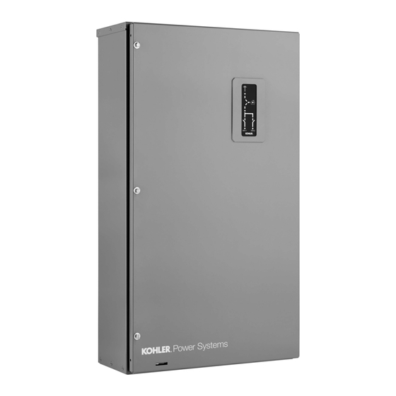
Figure 1 PowerSyncr Automatic Paralleling Module
GM85144-KP1-QS and Circuit Breaker Kits GM86368-KP1-QS and
GM86369-KP1-QS
allowing
and
generator
zab26291
The following combinations of single-phase
generator sets can be paralleled:
Two single-phase model 14RESA or 14RCA
D
generator sets with the same 110/220, 115/230,
120/240, 220, 230, or 240 volt configuration
Two single-phase model 20RESA/B/C/D or 20RCA
D
generator sets (must have the same 110/220,
115/230, 120/240, 220, 230 or 240 volt configuration)
Automatic paralleling requires:
Two single-phase generator sets as shown above.
for
D
RDC2 controllers with blue circuit boards. If the
D
generator has a controller with a green or red circuit
board, replace it with a blue board controller.
Paralleling firmware APM RDC2 version 210.0.0 or
D
higher on each generator controller. Download the
paralleling firmware from the Service Support section
on KPRC.
Note: Contact the Residential Service Department
for assistance if the controllers have an
older version (e.g. 101.0.3) of paralleling
firmware.
One Automatic Paralleling Module (APM) kit
D
One Model RXT automatic transfer switch (ATS)
D
A load management device* is required if one
D
generator set cannot support the maximum total load.
A
personal
D
SiteTecht software version 3.5 or higher is required
for system setup.
A load management device* is necessary in order to
shed non-critical loads in the event that one generator
set shuts down and the other generator set cannot
support all of the loads.
* A load management device is a load control module (LCM), load
shed kit, or combined interface/ load management board on the
RXT ATS.
TT-1596 8/22g
computer
(laptop)
with
Kohlerr
Advertisement
Table of Contents

Related Manuals for Kohler 14RESA


Summary of Contents for Kohler 14RESA
- Page 1 TT-1596 8/22g INSTALLATION AND OPERATION INSTRUCTIONS Original Issue Date: 8/12 Model: 14RESA, 20RESA, 20RESB, 20RESC, 20RESD, 14RCA and 20RCA Market: Residential/Light Commercial Subject: PowerSyncr Automatic Paralleling Module (APM) Kit GM85144-KP1-QS and Circuit Breaker Kits GM86368-KP1-QS and GM86369-KP1-QS Introduction The following combinations of single-phase...
- Page 2 APM enclosure. OnCuer Plus Generator Management System Figure 2 shows the circuit breaker kit numbers for the If OnCue Plus will be used, a unique OnCue activation 14RESA, 14RCA, 20RESA/B/C/D 20RCA code is required for each generator set. Two activation generator sets.
-
Page 3: Related Literature
Related Literature Disabling the generator set. Accidental starting can cause severe injury or death. Before working on the generator set or equipment connected to the set, disable the A single-phase paralleling system is made up of the generator set as follows: (1) Press the generator set off/reset APM module covered by this instruction sheet plus two button to shut down the generator set. -
Page 4: Installation Procedure
1 Installation Procedure 4. Connect the CT harness to connector P3 on the RDC2 controller inside the generator set. See Read the entire installation procedure and compare the Figure 6. kit parts with the parts list at the end of this publication before beginning installation. - Page 5 RBUS RBUS Figure 7 Block Diagram for Paralleling System Components and Connections TT-1596 8/22...
- Page 6 1.2 Install the automatic paralleling 5. Install the adaptor harnesses for voltage sensing connection: module (APM). a. Disconnect the generator set harness at P2 on 7. To remove the enclosure’s front panel, support the the back of the RDC2 controller. See Figure 6. panel while removing the screws.
- Page 7 1.3 Install the circuit breaker kit, if 11. Install circuit breaker mounting bracket GM85151 onto the back wall of the APM enclosure: required. a. Remove the 4 existing screws X-67-133 and 8 Note: The circuit breaker kit may be required if the APM existing washers X-25-36 from the back wall of is not installed within sight of the generator sets.
- Page 8 12. Mount two circuit breakers onto the bracket. For the 20RESA/B/C/D and 20RCA, 100 amp circuit breakers: For the 14RESA and 14RCA, 70 amp circuit breakers: c. Use 2 X-67-132 thread-forming screws to a. Use 4 X-67-132 thread-forming screws and 4 attach each circuit breaker to the mounting X-400-145 spacers for each circuit breaker.
- Page 9 Remove the larger portion on the left side of each knockout for the 70 amp breakers (14RESA and 14RCA) OR b. Remove both portions of the knockout for the 100 amp breakers (20RESA/B/C/D and 20RCA).
-
Page 10: Voltage Sensing
2 Connections 2.1 Voltage Sensing 4. Connect the voltage sensing leads from both After the physical installation of the paralleling system adaptor harnesses installed in the generator components, make the electrical connections described compartment in step 5 to terminal block TB1 in the in this section. - Page 11 2.2 RBUS Communication Connections short runs, or use 12- 14 AWG cable for longer runs as shown in Figure 15. Note: The RBUS communication wiring to the APM must be connected directly to the generator sets Note: All communication cables must be routed as shown in Figure 7.
- Page 12 APM PIB DIODE BOARD Load shed kit Note: See Figure 15 for maximum total cable length. Note: The APM, RXT, PIM, and/or load shed kit may be equipped with an alternate single-row connector for P10. See TP- 7239 for instructions to splice the PWR and COM connections.
- Page 13 2.3 AC Voltage Output Connections 2.4 Ethernet Connection for OnCue Plus 6. Connect generator set AC output leads to the APM 8. If OnCuer Plus will be used, connect both RDC2 contactors or to the circuit breakers installed in controllers to the Internet by connecting to the Section 1.3, if used.
- Page 14 3.3 Set the time, date, and exercise set controller. schedule on the primary generator set. Note: A personal computer (laptop) with Kohler SiteTecht software is required to complete the 1. The RDC2 display on each generator set will system installation and setup.
-
Page 15: Setup And Commissioning
Check the Network Information and Remote Devices controller to set up the PIM inputs and outputs. See menus on the RDC2 controller, or use Kohler SiteTech to TT-1584, provided with the PIM, for the default check the RBUS Devices group parameters. - Page 16 4.4 Perform the auto-discovery Troubleshooting Auto-Discovery procedure. If the connection LED on the APM fails to illuminate or the relays do not cycle, check the following: Note: This procedure is REQUIRED. Check the wiring between the generator and the 1. Close the circuit breakers on both generator sets APM.
-
Page 17: Final Adjustments
4.5 Verify synchronization and 3. Verify that the generators start, synchronize and close both contactors. This will enable the calibration. controllers to verify the metering. The engines may appear slightly unstable during the verification 1. Start generator 1 by pressing RUN on the RDC2 process. -
Page 18: Operation
5 Operation Synchronizing also verifies that the bus voltage is not appreciably different than the generator voltage. If the voltage is significantly different, the controller will adjust 5.1 Synchronization and Paralleling the generator voltage to match. This is why the bus voltage must be calibrated as described in Section 4.5. - Page 19 5.3 Generator Management If any voltage dip is observed (typically by dimming lights) when a generator closes the paralleling contactor paralleling system performs generator after synchronizing, it may be necessary to determine if management as described below. the fuel systems of the generators are allowing them to maintain a stable speed.
- Page 20 Generator Management will start the second generator Notes about Load Shed Settings and run it for at least 5 minutes if it senses any of the Compare the APM settings to the settings on the load following: management device. The running generator fails (disconnects from the Set the Generator Overload Percent setting on the paralleling bus).
- Page 21 5.3.2 Order of Operation Auto-Off Functionality Pressing the Auto and Off buttons simultaneously will There are two methods for selection of the generator set cause the generator to attempt to unload and order of operation: runtime hours selection mode and disconnect from the bus.
-
Page 22: Generator Set Maintenance
5.4 Generator Set Maintenance 5.5 Faults When it is necessary to perform maintenance or service Fault messages displayed on the RDC2 controller are on the generator sets, use the following procedure to shown in Figure 22 and Figure 23. remove one generator set from the system at a time. To clear the warnings listed in Figure 22 press AUTO or 1. - Page 23 Fault Text Description Possible Causes CfgModelNum The two generators which are intended to be Incorrect configuration of one of the paralleled have different model numbers. generators. Different generator types. The paralleled generator sets must be the same kW model. (i.e. two 14RESAs/14RCAls, two 20RESA/B/C/D/20RCAs.) LossOfComm2...
- Page 24 Fault Text Description Possible Causes LossOfField This generator has absorbed more than 25% reactive Generator voltage on this generator is not power (magnetic excitation current) for 20 seconds calibrated correctly. Generator voltage on other generator is not calibrated correctly. Bus voltage on this generator is not calibrated correctly.
-
Page 25: Status Indicators
5.6 Status Indicators The APM is equipped with an LED panel that indicates the system status. See Figure 24 and Figure 25. Note: A model RXT transfer switch is required for power connection status indication. See Figure 25. TT1596 1. Utility power available* 2. -
Page 26: Oncue Plus Generator Management System
6 OnCue Plus Generator The primary and secondary generator sets can be changed using the RBUS settings on the RDC2 Management System controllers or using SiteTecht software to change the Modbus Master parameter. SiteTech version 3.5 or The APM kit includes two OnCuer activation codes to higher is required. -
Page 27: Additional Troubleshooting
7 Additional Troubleshooting If the paralleling system does not operate as expected, check the items in the following charts. Verify that both generator controllers have blue circuit boards. Section 4 also includes some troubleshooting tips for problems that may arise during the initial setup. Breaker will not close in RUN. - Page 28 Auto-discovery does not complete. Device may already have The wait for auto-discovery auto-discovered to a different Check whether the can be as long as 30 contactor. Set the engine Automatic Paralleling seconds. After 30 seconds model number select to a Module indicates that the expires, try to close the different model and then set it...
-
Page 29: Diagrams And Drawings
8 Diagrams and Drawings The paralleling system dimension drawing, wiring diagram, and schematic diagram are shown on the following pages. Also refer to Figure 7, Block Diagram, on page 5. Diagram or Drawing Drawing Number Page APM Dimension Drawing ADV-8518 Sheet 1 Sheet 2 Wiring Diagram... - Page 30 Figure 31 Dimension Drawing ADV-8518 Sheet 1 TT-1596 8/22...
- Page 31 Figure 32 Dimension Drawing ADV-8518 Sheet 2 TT-1596 8/22...
- Page 32 Figure 33 Wiring Diagram, GM85757 Sheet 1 TT-1596 8/22...
- Page 33 GM85757- A Figure 34 Wiring Diagram, GM85757 Sheet 2 TT-1596 8/22...
- Page 34 Figure 35 Schematic Diagram, GM85758, Sheet 1 TT-1596 8/22...
- Page 35 Figure 36 Schematic Diagram, GM85758, Sheet 2 TT-1596 8/22...
-
Page 36: Parts Lists
TT-1596 Screw, Tapping X-67-132 Availability is subject to change without notice. Kohler Co. reserves the right to change the design or specifications without notice and without any obligation or liability whatsoever. Contact your local Kohlerr generator set distributor for availability.
Need help?
Do you have a question about the 14RESA and is the answer not in the manual?
Questions and answers
where is the muffler located. is it something that i can change myself> the generator has gotten very loud.
The muffler on the Kohler 14RESA generator is located above the alternator. The alternator is described as a "big black round thing under the muffler." There is no information in the context about whether the muffler can be changed by the user.
This answer is automatically generated