Advertisement
What's in the box
First things first.
Here's what you'll find in the box.

You'll also need these tools:

Optional:

Guide 1 or Guide 2? Start here to find out. The steps in this section will help you decide which install guide you'll use to complete the installation.
These icons indicate useful tips and important reminders.


Start Your Install
- Power off your Heating, Ventilation, and Air Conditioning (HVAC) system by using the master switch or circuit breaker box. This is important for your safety.
![]() TIP Look for your master switch or circuit breaker box in the basement, attic, utility closet, or behind a wall panel near the thermostat.
TIP Look for your master switch or circuit breaker box in the basement, attic, utility closet, or behind a wall panel near the thermostat.

- Confirm your system is off by turning on your heat (during winter) or your AC (during summer). Wait a few minutes—you should not feel air coming from your vents.
![]() TIP If you have a boiler, check to see that the main flame is extinguished.
TIP If you have a boiler, check to see that the main flame is extinguished.

- Remove your old thermostat cover from the wall.
![]() TIP Many thermostats simply pop off or unclip from the base, while others may have screws that you will need to remove.
TIP Many thermostats simply pop off or unclip from the base, while others may have screws that you will need to remove.


 CHECKPOINT: COMPATIBILITY
Does your old thermostat's backplate have any of these indicators?

YES
Sadly, you might not be compatible.
You can double-check here: ecobee.com/compatibility
NO
Great, please continue to the next.
- Take a picture of the wires connected to the terminals of your old thermostat. You may need to reference this photo later on.
![]()
ecobee4 is designed for 24VAC with a 2A maximum current. Do not connect it to line (high) voltage or millivolt systems.


CHECKPOINT: C WIRE
Do you have a C wire connected to your old thermostat?

Continue to Guide 1

Continue to Guide 2
GUIDE 1
Install your ecobee with a C wire
If you have a C wire, it will power your ecobee. You won't need the Power Extender Kit included in the box.

CHECKPOINT: DON'T SKIP AHEAD
Have you completed steps 1–4 in the 'Start Your Install' section?

YES
Continue to the next
NO
Return to step 1 in 'Start Your Install'
- Carefully disconnect and label the wires from your old thermostat one at a time, using the labels provided.


TIP 1
If you have a jumper between Rc, Rh, or R, leave it alone. Only label the wires that run from your wall into a terminal block.
TIP 2
To install accessories (humidifier, dehumidifier or ventilator) please refer to the wiring diagrams in the 'Extras' section.
- Unscrew the mounting plate of your old thermostat to remove it from the wall.


Be careful, as some thermostats may contain mercury. Recycle your old thermostat safely with your local hazardous waste facility.
- Decide if you want to use the trim plate with your ecobee. The trim plate is useful if you want to hide marks or holes left on the wall by your old thermostat.

- OPTIONAL
If using the trim plate, align the mounting holes on the trim plate and backplate and press them into place together.

- Pull the wires through the hole in the middle of the backplate and then attach the backplate to the wall using the drywall anchors and screws provided.


TIP Use a 3/16" drill bit to drill a hole for the drywall plugs.
CHECKPOINT: INSERT YOUR R WIRE(S)
Do you have more than one R wire? (That includes R, Rc, and Rh)

Insert your wires:
R or Rc  Rc
Rc
Rh Rh

Insert your single R, Rc, or Rh wire into the Rc terminal.
- Insert your remaining wires into the side (not the front) of their corresponding terminal blocks.


TIP Press the terminal block levers to insert the wires more easily.
- Tug on the wires gently to ensure they are securely connected.


TIP When a wire has been connected correctly, the lever on that block will lower.
- Carefully push any excess wires back into the hole and ensure there are no drafts coming from the hole(s) in the wall.


TIP Large holes behind your thermostat will affect temperature readings. Prevent drafts by covering the hole(s).
- Gently press your ecobee into the backplate until it 'clicks' into place.


TIP If the thermostat 'rocks' or is not flush with the wall, be sure the excess wires are pushed all the way into the wall.
- Turn the power to your HVAC system back on using the master switch or at the circuit breaker box.

- Say hi to your new ecobee! The screen will power on and guide you through the setup and registration.


TIP If your thermostat does not power on, please see the troubleshooting tips in the 'Extras' section.
ALL DONE!
Congratulations, you did it!
To complete your setup, follow the instructions on your ecobee screen.
GUIDE 2
Install your ecobee without a C wire
If you don't have a C wire, you'll need to use the Power Extender Kit (PEK) included to reliably power your ecobee.

CHECKPOINT: DON'T SKIP AHEAD
Have you completed steps 1–4 in the 'Start Your Install' section?

YES
Continue to the next.
NO
Return to step 1 in 'Start Your Install'
CHECKPOINT: 3 OR 4 WIRES
The Power Extender Kit requires your system to have the following wires: 4 wires:
W/W1, Y/Y1, G, and R (or Rc or Rh) or 3 wires: Y/Y1, G, and R (or Rc or Rh)
Do you have these wires?

Continue to the next
The Power Extender Kit will work with your system!

Contact us
To proceed call 1.877.932.6233 or email support@ecobee.com
- Take your Power Extender Kit, wire labels, tools, your smartphone, and go to your HVAC system.


TIP Your HVAC system can most often be found in your basement or your attic.
- Open your HVAC system's cover to reveal the control board.


HVAC systems contain high voltage wires. Use caution when working with the control board.
- Take a picture of the wires connected to your control board. You may need to reference this photo later on.

- Label only the R, Y or Y1, G, and W or W1 wires with the matching labels provided. If you have more than one wire going into these terminals, only label those going to your thermostat.


TIP If you have wires connected to both Rc and Rh terminals at the controlboard you may have a two transformer system. Please contact support to help you with installation: 1.877.932.6233 or support@ecobee.com.
- Disconnect the wires labeled R, Y, G, and W from the control board.

- Connect the wires you disconnected from the control board into their matching gray terminal blocks on the Power Extender Kit.


TIP Press the buttons to insert the wires more easily.
- Tug on the wires gently to ensure they are securely connected.


TIP When a wire has been connected correctly, the button on that block will lower.
- Connect the five white wires coming out of your Power Extender Kit to their corresponding terminals on the control board.


TIP Once again, tug on the wires gently to ensure they are securely connected.
CHECKPOINT: POWER EXTENDER KIT
Check that you have installed the Power Extender Kit correctly. It should be installed between your thermostat wiring and your control board.

- Mount the Power Extender Kit inside your HVAC system, taking care not to strain the wires. Close the HVAC cover panel securely and return to your thermostat.


TIP Make sure your HVAC panel is fully closed. Some systems will not turn on if the cover panel has not been closed properly.
- Back at your thermostat:
Carefully disconnect and label the wires from your old thermostat one at a time, using the labels provided.


TIP If you have a jumper between Rc, Rh, or R, leave it alone. Only label the wires that run from your wall into a terminal block.
- Unscrew the mounting plate of your old thermostat to remove it from the wall.
![]()
Be careful, as some thermostats may contain mercury. Recycle your old thermostat safely with your local hazardous waste facility.

- Decide if you want to use the trim plate with your ecobee. The trim plate is useful if you want to hide marks or holes on the wall left by your old thermostat.

- OPTIONAL
If using the trim plate, align the mounting holes on the trim plate and backplate and press them into place together.

- Pull the wires through the hole in the middle of the backplate and then attach it to the wall using the drywall anchors and screws provided.


TIP Use a 3/16" drill bit to drill a hole for the drywall plugs.
- Remove the Rc, C, and PEK labels from the label sheet and attach them to the wires as shown below:
R/Rc/Rh![]() Rc
Rc
G![]() C
C
Y![]() PEK
PEK

- First, connect these 3 wires as shown:
Rc, C, PEK
Then, connect any remaining wires to their corresponding terminal.


TIP Press the terminal block levers to insert the wires more easily.
CHECKPOINT: DON'T SKIP AHEAD
Did you connect the correct wires to the Rc, C, and PEK terminals, as shown below?

YES
Continue to the next.
NO
Return to Step 19.
- Tug on the wires gently to ensure they are securely connected.

TIP When a wire has been connected correctly, the lever on that block will lower.
- Carefully push any excess wires back into the hole and ensure there are no drafts coming from the hole(s) in the wall.


TIP Large holes behind your thermostat will affect temperature readings. Prevent drafts by covering the hole(s).
- Gently press your ecobee into the backplate until it 'clicks' into place.


TIP If the thermostat 'rocks' or is not flush with the wall, be sure the excess wires are pushed all the way into the wall.
- Turn the power to your HVAC system back on using the master switch or at the circuit breaker box.

- Say hi to your new ecobee! The screen will power on and guide you through the setup and registration.


TIP If your thermostat does not power on, please see the troubleshooting tips in the 'Extras' section.
ALL DONE!
Congratulations, you did it!
To complete your setup, follow the instructions on your ecobee screen.
TROUBLESHOOTING
If your ecobee doesn't turn on
Please try these steps:
- Check that all wires are properly inserted into the terminal blocks at the thermostat. Tug on the wires to ensure they are not loose.


- Make sure your HVAC cover panel is closed. Some systems will not turn on if the cover panel has not been closed properly.


- If you have only one R wire (either R, Rc, or Rh ), make sure it's inserted into the Rc terminal.


- If you installed the Power Extender Kit, make sure you inserted the wires into the correct terminals:


ecobee support is here to help:
CALL
1 877.932.6233 (North America)
1 647.428.2220 (International)
EMAIL
support@ecobee.com
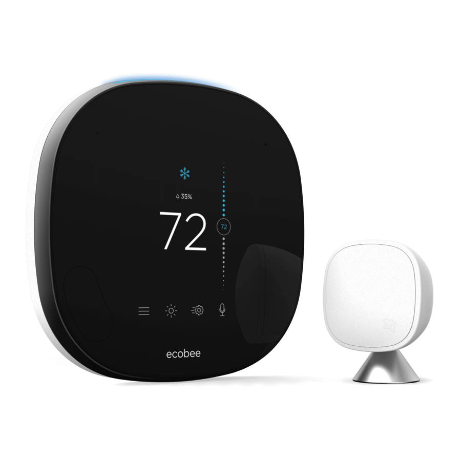
MEET YOUR ECOBEE
Here's what you'll see on the home screen:

And here's what that means:
System Mode
Shows your current ecobee setting (heat/cool/auto/off).
Humidity
Shows the indoor humidity in your home.
Indoor Temperature
Shows the indoor temperature in your home.
Slider to adjust Temperature
Slide the bubble up or down to adjust your preferred temperature.
Menu
Allows you to control your system, schedule a vacation, and more.
Weather
Shows the local weather and forecast for the week.
Quick Changes
Touch this button to easily switch between Home and Away.
Voice Control
Allows you to turn volume up/down and enable/disable microphone.
These system mode icons are shown on the Home screen and in Quick Changes.
Heat

Your system is in heat mode. A white icon means your system is off. An orange icon means your system is running.
Auto

Your system is in Auto mode, meaning your system will heat or cool as required.
Cool

Your system is in cool mode. A white icon means your system is off. A blue icon means your system is running.
Fan

Your fan is currently running.
More common icons you'll find:
HOME SCREEN
 |  |  |  |
| Menu | Menu (with notification) | Weather | Quick Changes |
MENU
 |  |  |  |
| Registration | System | Settings | Schedule |
 |  |  |  |
| Vacation | Alerts and | Comfort Settings | About |
COMFORT SETTINGS
 |  |  |  |
| Home | Away | Sleep | Custom 1 (of 5) |
VOICE
 |  |  |
| Voice Control | Microphone Off | Push to Talk |
WIRING DIAGRAM
Conventional heating and cooling (up to 2 stages each).

NOTE Do not connect any jumper wires between Rc and Rh. ecobee does this automatically. The R wire needs to go into the Rc terminal on your ecobee.
Heat pump (air or geothermal) with auxiliary heat.

NOTE Do not connect any jumper wires between Rc and Rh. ecobee does this automatically. The R wire needs to go into the Rc terminal on your ecobee.
Boiler or radiant system with air handler and conventional cooling or heating.

NOTE Do not connect any jumper wires between Rc and Rh. ecobee does this automatically. The R wire needs to go into the Rc terminal on your ecobee.
Power Extender Kit thermostat wiring.

NOTE Do not connect any jumper wires between Rc and Rh. ecobee does this automatically. The R wire needs to go into the Rc terminal on your ecobee.
HUMIDIFIER / DEHUMIDIFIER (1-WIRE SETUP)
- Locate the humidifier/dehumidifer control and remove the plate.
 - Step 1")
- Wire the humidifier/dehumidifer as shown below.
 - Step 2")
 - Step 1")
 - Step 2")
NOTE During setup, select 1-wire (ACC+) accesory on the thermostat screen.
HUMIDIFIER / DEHUMIDIFIER (2-WIRE SETUP)
- Locate the humidifier/dehumidifer control and remove the plate.
 - Step 1")
- Wire the humidifier/dehumidifer as shown below.
 - Step 2")
 - Step 1")
 - Step 2")
NOTE During setup, select 2-wire (ACC+, ACC-) accesory on the thermostat screen.
VENTILATOR (2-WIRE SETUP)
- Locate the ventilator timer control and remove the plate.
 - Step 1")
- Wire the ventilator as shown below.
 - Step 2")
 - Step 1")
 - Step 2")
NOTE During setup, select 2-wire (ACC+, ACC-) accesory on the thermostat screen.
Download the ecobee app for customized installation instructions.


ecobee.com
support@ecobee.com 1.877.932.6233 © 2016 ecobee, Inc.
All rights reserved. ecobee and the ecobee logo are trademarks of ecobee Inc., registered in the U.S. and other countries.

Documents / Resources
References
Download manual
Here you can download full pdf version of manual, it may contain additional safety instructions, warranty information, FCC rules, etc.
Advertisement


Need help?
Do you have a question about the ecobee4 and is the answer not in the manual?
Questions and answers