ABB ACQ580-34 Quick Installation Manual
Drive modules
Hide thumbs
Also See for ACQ580-34:
- Hardware manual (244 pages) ,
- Quick installation manual (22 pages) ,
- Manual (16 pages)
Table of Contents
Advertisement
Available languages
Available languages
Quick Links
—
ABB DRIVES FOR WATER
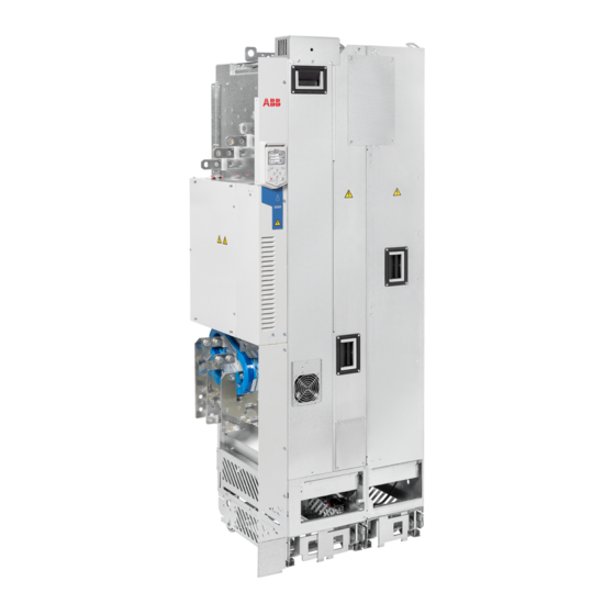
ACQ580-34 drive modules
Quick installation guide
English. . . . . . . .
3
Dansk . . . . . . .
17
Deutsch . . . . . .
23
Español . . . . . .
29
Suomi . . . . . . .
35
Français. . . . . .
41
Italiano . . . . . . .
47
Dutch . . . . . . . .
53
Polski. . . . . . . .
59
Português . . . .
65
Русский . . . . . .
71
Svenska. . . . . .
77
Türkçe . . . . . . .
83
中文 . . . . . . . . .
89
EN
DA
DE
ES
FI
FR
IT
NL
PL
PT
RU
SV
TR
ZH
Advertisement
Table of Contents

Related Manuals for ABB ACQ580-34


Summary of Contents for ABB ACQ580-34
- Page 1 — ABB DRIVES FOR WATER ACQ580-34 drive modules Quick installation guide English..Dansk ..Deutsch ..Español ..
-
Page 2: List Of Related Manuals
Code (English) 3AXD50000037978 Drive/converter/inverter safety instructions 3AXD50000420025 ACQ580-34 drive modules hardware manual 3AXD50000424634 ACQ580-34 drive modules quick installation guide 3AUA0000085685 ACx-AP-x Assistant control panels user’s manual 3AXD50000137688 Recycling instructions and environmental information for ACS880-04, ACS880-14, ACS880-34, ACS580-04, ACQ580-04 and ACH580-04 drives... -
Page 3: Contents Of This Guide
EN – Quick installation guide 3 EN – Quick installation guide Contents of this guide This guide tells you briefly how to install the drive module into a 800 mm wide Rittal VX25 enclosure. Obey the safety instructions General safety ... - Page 4 4 EN – Quick installation guide • Make sure that the module does not topple over when you move it on the floor: To open the support legs, press each leg a little down and turn it aside (1, 2). Whenever possible attach the module also with chains.
-
Page 5: Electrical Safety Precautions
EN – Quick installation guide 5 Electrical safety precautions These electrical safety precautions are for all personnel who do work on the drive, motor cable or motor. WARNING! Obey these instructions. If you ignore them, injury or death, or damage to the equipment can occur. -
Page 6: Select The Power Cables
AC and VAR wires. a corner-grounded VAR wires. wire. system. 1) A residual current device must be installed in the supply system. 2) ABB does not guarantee the EMC category or the operation of the ground leakage detector built inside the drive. - Page 7 EN – Quick installation guide 7 Move the drive to the installation site and unpack it 3AXD50000174287_20210204 Step Transport package contents Finger guard Pedestal guide plate for the LCL filter module Pedestal guide plate for the drive module Accessories box See the box contents on the following pages.
- Page 8 8 EN – Quick installation guide Step Transport package contents VCI film or bag Drive module with factory installed options and multilingual residual voltage warning sticker, fastening screws in a plastic bag, control panel and cable or control panel with door mounting kit (option +J410), delivery documents, printed multilingual installation and start-up quick guides.
- Page 9 EN – Quick installation guide 9 Output connection terminals box with standard drive module configuration Paper fill Output cable connection terminal T3/W2 Output cable connection terminal T2/V2 Output cable connection terminal T1/U2 Grounding terminal Cardboard box Screws and insulators in a plastic bag 3AXD5000009515 Accessories box Screw package...
- Page 10 10 EN – Quick installation guide LCL filter module package 3AXD50000113651 VCI bag Plywood support Lid for cardboard sleeve Cardboard sleeve Cardboard support Pallet Strap LCL filter module...
- Page 11 EN – Quick installation guide 11 Install the drive module and LCL filter module into an enclosure Step-by-step drawings for an installation example of standard drive configuration in Rittal VX25 800 mm wide enclosure (page 105). Step Tasks Mechanical accessories Attach the plinth to the floor.
- Page 12 12 EN – Quick installation guide Step Tasks Push the drive module carefully into the enclosure along the extraction/installation ramp. Work preferably with help from another person as shown above. Keep a constant pressure with one foot on the base of the module to prevent the module from falling on its back. Unfasten the extraction/installation ramp and attach the drive module to the bottom plate.
- Page 13 EN – Quick installation guide 13 Connect the input cables and install the shrouds (option +B051) Step-by-step drawings for an installation example of standard drive configuration in Rittal VX25 800 mm wide enclosure (page 105). Step Tasks (input cables) Ground the input cable shields (if present) 360 degrees at the enclosure entry. Connect the twisted shields of the input cables and separate ground cable (if present) to the enclosure grounding busbar.
-
Page 14: Connect The Control Cables
14 EN – Quick installation guide Connect the control cables Connect the conductors of external control cables to the appropriate terminals of the control unit. See section Default I/O diagram (Water default) (page 15). 1. Ground the outer control cable shields 360 degrees at the cabinet entry plate (recommendation). - Page 15 EN – Quick installation guide 15 Default I/O diagram (Water default) Reference voltage and analog inputs and outputs Signal cable shield (screen) Output frequency/speed reference: 0…10 V 1…10 kohm AGND Analog input circuit common +10V Reference voltage 10 V DC Actual feedback: 0…10 V AGND Analog input circuit common...
- Page 16 16 EN – Quick installation guide Notes: 1. Current [0(4)…20 mA, R = 100 ohm] or voltage [0(2)…10 V, R >200 kohm]. Change of setting requires changing the corresponding parameter. 2. Total load capacity of the Auxiliary voltage output +24V (X2:10) is 6.0 W (250 mA / 24 V) minus the power taken by the option modules installed on the board.
-
Page 17: Overhold Sikkerhedsinstruktionerne
800 mm bredt Rittal VX25-kabinet. For oplysninger om installationseksempler for andre kabinetter og for flere detaljerede instruktioner, tekniske retningslinjer, tekniske data og komplette sikkerhedsinstruktioner henvises til hardwaremanualen (www.abb.com/drives, Vælg Document Library og søg på dokumentnummer (på engelsk)). Overhold sikkerhedsinstruktionerne Se figurerne på... -
Page 18: Vælg Effektkabler
18 DA – Hurtig installationsvejledning 5. Kontroller, at installationen ikke er strømførende. • Brug et multimeter med en impedans på mindst 1 Mohm. • Sørg for, at spændingen mellem frekvensomformermodulets indgangseffektterminaler (L1/U1, L2/V1, L3/W1) og jordskinnen (PE) er tæt på 0 V. - Page 19 DA – Hurtig installationsvejledning 19 3AUA0000088632 • Løsn indsættelsesrampen og fastgør LCL-filtermodulet til bundpladen. • Fastgør frekvensomformermodulets styreplade til kabinettets bundplade. • Fastgør den teleskopiske rampe til indsættelse på soklens styreplade. • Fjern beskyttelsen fra frekvensomformerens gennemsigtige plastikafdækninger på begge sider. •...
- Page 20 20 DA – Hurtig installationsvejledning Trin Opgaver (motorkabler) Skru og spænd med hånden isolationen på frekvensomformermodulet. Monter T3/W2- tilslutningsterminalen i isolationen. ADVARSEL! Undgå at bruge længere skruer eller større tilspændingsmoment end angivet i monteringstegningen. De kan ødelægge isolationen og forårsage, at der findes farlig spænding i modulrammen.
- Page 21 OUT2 skal være lukkede, for at frekvensomformeren kan starte. Se kapitlet The Safe torque off SGND function i ACQ580-34 hardware manual 3AXD50000420025 (på engelsk)). 24 V AC/DC 24 V AC/DC+ in Eks. 24V AC/DC-indgang til start af styreenheden, når netforsyningen er frakoblet.
- Page 22 22 DA – Hurtig installationsvejledning...
-
Page 23: Inhalt Dieser Anleitung
Frequenzumrichtermoduls in einen 800 mm breiten Rittal VX25 Schrank. Beispiele für den Einbau in verschiedene Schränke sowie weitere Informationen, Planungsrichtlinien, technische Daten und die vollständigen Sicherheitsvorschriften finden Sie im Hardware- Handbuch (www.abb.com/drives. Wählen Sie Document Library und suchen Sie dann die Dokumentennummer [English]). Befolgen Sie die Sicherheitsvorschriften Siehe Abbildungen auf Seite 106. -
Page 24: Auswahl Der Leistungskabel
24 DE – Kurzanleitung für die Installation 5. Stellen Sie durch Messungen sicher, dass die gesamte Installation spannungsfrei ist. • Verwenden Sie Multimeter mit einer Impedanz von mindestens 1 MOhm. • Sicherstellen, dass die Spannung zwischen den Eingangsspannungsklemmen (L1/U1, L2/V1, L3/W1) und der Erdungsschiene (PE) nahe 0 V ist. •... - Page 25 DE – Kurzanleitung für die Installation 25 3AUA0000088632 • Die Rampe entfernen und das LCL-Filtermodul an der Bodenplatte befestigen. • Das Führungsblech des Frequenzumrichtermodul-Sockels auf der Bodenplatte des Schrank befestigen. • Die Teleskoprampe am Sockelführungsblech befestigen. • Die Schutzfolie auf beiden Seiten von den durchsichtigen Kunststoffabdeckungen des Frequenzumrichtermoduls entfernen.
- Page 26 26 DE – Kurzanleitung für die Installation Anschluss der Leistungskabel und Installation der Abdeckungen Schritt Aufgabe (Motorkabel) Die Erdungsklemme am unteren Teil des Frequenzumrichtermoduls befestigen. Die Motorkabel in den Schrank führen. Die Kabelschirme am Schrankeingang 360° erden. Die verdrillten Schirme der Motorkabel an die Erdungsklemme anschließen. Die Isolatoren mit der Hand in das Frequenzumrichtermodul eindrehen und festziehen.
- Page 27 Werksseitiger Anschluss. Beide Kreise müssen für den OUT2 Start des Antriebs geschlossen sein. Siehe Kapitel SGND Funktion Sicher abgeschaltetes Drehmoment im ACQ580-34 Hardware-Handbuch (3AXD50000420025 [englisch]). 24 V AC/DC 24 V AC/DC+ in Ext. 24V AC/DC Spannungsversorgung der Regelungseinheit, wenn der Frequenzumrichter vom Netz getrennt ist.
- Page 28 28 DE – Kurzanleitung für die Installation...
-
Page 29: Contenido De Esta Guía
Rittal VX25 de 800 mm de anchura. Para obtener ejemplos de instalación en otros armarios, instrucciones más detalladas, directrices de ingeniería, datos técnicos y unas instrucciones de seguridad completas, véase el Manual de hardware (vaya a www.abb.com/drives, selecccione Document Library y busque el número de documento [Inglés]). Siga estrictamente las instrucciones de seguridad Véanse las figuras en la página 106. -
Page 30: Garantice La Refrigeración
30 ES – Guía rápida de instalación 5. Compruebe que la instalación está desenergizada. • Utilice un multímetro con una impedancia de al menos 1 Mohmio. • Asegúrese de que la tensión entre los terminales de potencia de entrada del módulo de convertidor (L1/U1, L2/V1, L3/W1) y el embarrado de conexión a tierra (PE) sea aproximadamente 0 V. - Page 31 ES – Guía rápida de instalación 31 se muestra a continuación. Mantenga un pie apoyado en la base del módulo para evitar que caiga hacia atrás. 3AUA0000088632 • Suelte la rampa de inserción y fije el módulo de filtro LCL a la placa inferior. •...
- Page 32 32 ES – Guía rápida de instalación Conexión de los cables de potencia e instalación de las cubiertas protectoras Paso Tarea (cables de motor) Instale el terminal de conexión a tierra en la base del módulo de convertidor. Tienda los cables de motor hasta el armario. Conecte a tierra los apantallamientos del cable a 360 grados de la entrada del armario.
- Page 33 ES – Guía rápida de instalación 33 Paso Tarea (cables de entrada) Instale el terminal de conexión L3/W1 en los aislantes. Véase la advertencia del paso 6. Conecte los conductores L3/W1 al terminal de conexión L3/W1. Instale la cubierta de entrada de plástico transparente. Instale la cubierta frontal de plástico transparente y la cubierta frontal superior.
- Page 34 OUT2 deben estar cerrados para que el convertidor pueda SGND ponerse en marcha. Véase el capítulo Función Safe Torque Offen el Manual de hardware del ACQ580-34 (3AXD50000420025 [Inglés]). 24 V CA/CC 24 V CA/CC+ in Entr. ext. de externa de 24 V CA/CC para alimentar la unidad de control cuando se desconecta la alimentación principal.
-
Page 35: Noudata Turvaohjeita
Tässä oppaassa kuvataan lyhyesti taajuusmuuttajamoduulin asentaminen 800 mm leveään Rittal VX25 -kaappiin. Asennusesimerkkejä eri kaapeista, yksityiskohtaisemmat ohjeet, suunnitteluohjeet, tekniset tiedot ja täydelliset turvaohjeet löytyvät laiteoppaasta (www.abb.com/drives, valitse Document Library ja etsi asiakirjanumerolla [englanninkielinen]). Noudata turvaohjeita Katso kuvat sivulla 106. Ohjeiden huomiotta jättämisestä voi seurata ruumiinvamma, kuolema tai laitteiston vahingoittuminen. -
Page 36: Valitse Tehokaapelit
36 FI – Asennuksen pikaopas 5. Varmista mittauksilla, että järjestelmä on jännitteetön. • Käytä yleismittaria, jonka impedanssi on vähintään 1 Mohm. • Varmista, että taajuusmuuttajamoduulin syöttöliitäntöjen (L1/U1, L2/V1, L3/W1) ja maadoituskiskon (PE) välinen jännite on lähes 0 V. • Varmista, että taajuusmuuttajamoduulin UDC+- ja UDC– -liittimien ja maadoitusliittimen (PE) välinen jännite on lähes 0 V. - Page 37 FI – Asennuksen pikaopas 37 3AUA0000088632 • Irrota ramppi ja kiinnitä LCL-suodinmoduuli pohjalevyyn. • Kiinnitä taajuusmuuttajamoduulin jalustan ohjauslevy kaapin pohjalevyyn. • Kiinnitä teleskooppiramppi jalustan ohjauslevyyn. • Poista suojamuovi taajuusmuuttajamoduulin läpinäkyvien muovisuojien molemmilta puolilta. • Asenna taajuusmuuttajamoduuliin metallinen yläsuojus. • Asenna taajuusmuuttajamoduuliin takasuojukset. •...
- Page 38 38 FI – Asennuksen pikaopas Vaihe Toimenpide (moottorikaapelit) Ruuvaa ja kiristä taajuusmuuttajan eristeet paikoilleen käsin. Asenna eristeisiin T3/W2-liitäntä. VAROITUS! Älä käytä asennuspiirustuksessa kuvattua suurempia ruuveja tai suurempaa kiristysmomenttia. Ne voivat vahingoittaa eristettä ja aiheuttaa vaarallisen jännitteen syntymisen moduulin runkoon. Kytke vaiheen T3/W2 johtimet T3/W2-liitäntään. Asenna eristeisiin T2/V2-liitäntä.
- Page 39 FI – Asennuksen pikaopas 39 Oletusarvoiset I/O-kytkennät Vesijärjestelmien oletuskokoonpanon oletusarvoiset I/O-kytkennät on esitetty seuraavassa kaaviossa. Johdinkoot: 0,14…2,5 mm : kaikki liittimet. Kiristysmomentit: 0,5…0,6 Nm. Ohjejännite ja analogiatulot ja -lähdöt Ohjauskaapelin suoja Lähtötaajuuden/nopeuden ohjearvo: 0 … 10 V 1…10 kohm AGND Analogiatulopiirin maa +10V Ohjejännite 10 V DC...
- Page 40 40 FI – Asennuksen pikaopas...
-
Page 41: Contenu De Ce Guide
(www.abb.com/drives, sélectionnez Document Library (Téléchargements) et entrez le code du manuel anglais ). Consignes de sécurité... -
Page 42: Sélection Des Câbles De Puissance
42 FR – Guide d'installation 5. Vérifiez par une mesure l'absence de tension dans l'installation. • Utilisez un multimètre d’une impédance d’au moins 1 Mohm. • La tension entre les bornes d’entrée du module variateur (L1/U1, L2/V1, L3/W1) et le jeu de barres de mise à la terre (PE) doit être proche de 0 V. •... - Page 43 FR – Guide d'installation 43 3AUA0000088632 • Détachez la rampe d'insertion et fixez le module filtre LCL sur la tôle de fond. • Montez la plaque de guidage inférieure du module variateur sur la tôle du bas de l'armoire. • Fixez la rampe télescopique d’insertion sur la plaque de guidage inférieure.
- Page 44 44 FR – Guide d'installation Étape Tâches (câbles moteur) Vissez et serrez manuellement les isolants sur le module variateur. Fixez la borne de raccordement T3/W2 sur les isolants. ATTENTION ! N'utilisez pas de vis plus longues ou de couple de serrage plus important que ce qui est indiqué...
-
Page 45: Raccordement Des Signaux D'e/S (Préréglages)
Interruption sécurisée du couple. Préraccordements OUT2 usine. Les deux circuits doivent être fermés pour SGND autoriser le démarrage du variateur. Cf. chapitre Fonction STO du manuel d'installation ACQ580-34 (3AXD50000420025). 24 V c.a./c.c. 24 V Entrée ext. 24 V c.a./c.c. pour mettre l’unité de commande sous tension lorsque l’alimentation principale est débranchée. - Page 46 46 FR – Guide d'installation...
-
Page 47: Rispettare Le Norme Di Sicurezza
Rittal VX25 di 800 mm di larghezza. Per gli esempi di installazione in altri armadi e istruzioni più dettagliate, linee guida ingegneristiche, dati tecnici e norme di sicurezza complete, si rimanda al Manuale hardware (www.abb.com/drives, selezionare Document Library e cercare il numero di documento [inglese]). -
Page 48: Selezione Dei Cavi Di Potenza
48 IT – Guida rapida all'installazione 5. Misurare che non siano presenti tensioni nell'installazione. • Utilizzare un tester con impedenza minima di 1 Mohm. • Accertarsi che la tensione tra i morsetti della potenza di ingresso del modulo convertitore (L1/U1, L2/V1, L3/W1) e la busbar di terra (PE) sia prossima a 0 V. •... - Page 49 IT – Guida rapida all'installazione 49 3AUA0000088632 • Sganciare la rampa di inserimento e fissare il modulo del filtro LCL alla piastra inferiore. • Installare la piastra guida del supporto del modulo convertitore sulla piastra inferiore del telaio dell'armadio. • Installare la rampa di inserimento telescopica sulla piastra guida del supporto.
- Page 50 50 IT – Guida rapida all'installazione Collegamento dei cavi di potenza e installazione delle protezioni Punto Attività (cavi motore) Installare il morsetto di terra alla base del modulo convertitore. Far passare i cavi motore nell'armadio. Mettere a terra le schermature dei cavi a 360° in corrispondenza dell'ingresso dell'armadio.
- Page 51 IT – Guida rapida all'installazione 51 Punto Attività (cavi di ingresso) Collegare i conduttori L3/W1 al morsetto di collegamento L3/W1. Installare la protezione in plastica trasparente dell'ingresso cavi. Installare la protezione anteriore in plastica trasparente e il coperchio anteriore in alto. Installare le protezioni in plastica trasparente laterale e superiore sul modulo convertitore.
- Page 52 52 IT – Guida rapida all'installazione Collegamenti degli I/O di default Di seguito sono mostrati i collegamenti di I/O di default della configurazione di default per il trattamento acque. Dimensioni fili: 0.14…2.5 mm (26...16 AWG): tutti i morsetti. Coppie di serraggio: 0.5…0.6 N·m (0.4 lbf·ft). Ingressi e uscite analogici e tensione di riferimento Schermatura cavo segnali (SCReen) Riferimento velocità/frequenza di uscita: 0…10 V...
-
Page 53: Volg De Veiligheidsvoorschriften
Deze gids vertelt in het kort hoe u de omvormermodule kunt installeren in een 800 mm brede Rittal VX25 kast. Zie, voor installatievoorbeelden in verschillende kasten en nadere instructies, technische richtlijnen, technische gegevens en complete veiligheidsinstructies, de hardwarehandleiding (www.abb.com/drives, Kies Document Library en zoek document nummer [Engels]). Volg de veiligheidsvoorschriften Zie de figuren op pagina 106. -
Page 54: Kies De Vermogenskabels
54 NL – Beknopte installatiegids 5. Meet dat er geen spanning op de installatie staat. • Gebruik een multimeter met een impedantie van minstens 1 Mohm. • Controleer dat de spanning tussen de voedingsklemmen van de omvormermodule (L1/U1, L2/V1, L3/W1) en de aardings- (PE) rail dicht bij 0 V ligt. •... - Page 55 NL – Beknopte installatiegids 55 3AUA0000088632 • Maak de hellingplaat los en bevestig de LCL filtermodule aan de bodemplaat. • Bevestig de geleidingsplaat voor het voetstuk van de omvormermodule aan de bodemplaat van de kast. • Bevestig de telescopische hellingplaat voor het invoegen aan de geleidingsplaat van het voetstuk.
- Page 56 56 NL – Beknopte installatiegids Aansluiten van de vermogenskabels en installeren van de afdekkingen Stap Taak (motorkabels) Monteer de aardaansluitklemmen op de onderkant van de omvormermodule. Leid de motorkabels naar de kast. Aard de kabelafschermingen over 360 graden bij de kast-invoer. Sluit de getwiste afschermingen van de motorkabels aan op de aardklem.
-
Page 57: Standaard I/O Aansluitingen
OUT2 circuits moeten gesloten zijn voordat de SGND omvormer kan starten. Zie het hoofdstuk The Safe torque off function in ACQ580-34 hardware manual (3AXD50000420025 [Engels]). 24 V AC/DC 24 V AC/DC+ in Ext. 24V AC/DC ingang om de besturingsunit in te schakelen wanneer de hoofdvoeding losgekoppeld is. - Page 58 58 NL – Beknopte installatiegids...
-
Page 59: Należy Przestrzegać Instrukcji Bezpieczeństwa
VX25 o szerokości 800 mm. Przykłady montażu w innych szafach oraz szczegółowe wska- zówki, wytyczne i dane techniczne wraz z pełnymi instrukcjami bezpieczeństwa zawiera pod- ręcznik użytkownika. Na stronie www.abb.com/drives należy wybrać pozycję Document Library (Biblioteka dokumentów) i wyszukać dokument o numerze [j. ang.]). -
Page 60: Dobór Kabli Zasilania
60 PL — Skrócona instrukcja montażu 5. Zmierzyć, czy instalacja nie jest zasilana. • Używać miernika uniwersalnego z impedancją co najmniej 1 MΩ. • Upewnić się, że napięcie pomiędzy zaciskami zasilania modułu przemiennika często- tliwości (L1/U1, L2/V1, L3/W1) oraz uziemieniem (PE) szyny zbiorczej jest bliskie 0 V. •... - Page 61 PL — Skrócona instrukcja montażu 61 3AUA0000088632 • Odczepić rampę i zamocować moduł filtra LCL do płyty dolnej. • Zamocować płytę z prowadnicą podstawy modułu przemiennika częstotliwości do płyty dolnej szafy. • Zamocować teleskopową rampę do płyty z prowadnicą podstawy. •...
- Page 62 62 PL — Skrócona instrukcja montażu Krok Zadanie (kable silnika) Ręcznie przykręcić izolatory do modułu. Zamontować zaciski złączy T3/W2 do izolatorów. OSTRZEŻENIE! Nie używać dłuższych wkrętów ani nie stosować większej siły dokręcenia niż przedstawiono na rysunku montażowym. Może to uszkodzić izolator i spowodować, że na obudowie modułu będzie występować...
-
Page 63: Domyślne Połączenia We/Wy
OUT2 mo liwe uruchomienie przemiennika cz stotliwo ci. SGND Patrz rozdzia The Safe torque off function w dokumencie ACQ580-34 hardware manual 3AXD50000420025 [j. ang.]). 24 V AC/DC 24 V AC/DC+ in Zew. Wej cie 24V AC/DC zasilaj ce jednostk steruj c , gdy g ówne zasilanie jest od czone. - Page 64 64 PL — Skrócona instrukcja montażu...
- Page 65 Rittal VX25 com 800 mm de largura. Para exemplos de instalação em diferentes armários e instruções mais detalhadas, indicações de engenharia, dados técnicos e instruções de segurança completas, consulte o manual de hardware em (www.abb.com/drives, Selecione Document Library e procure pelo número de documento [Inglês]).
- Page 66 66 PT - Guia rápido de instalação 5. Meça e verifique se a instalação está desligada. • Use a multímetro com uma impedância mínima de 1 Mohm. • Certifique-se de que a tensão entre os terminais de entrada de potência do módulo de acionamento (L1/U1, L2/V1, L3/W3) e o barramento de ligação à...
- Page 67 PT - Guia rápido de instalação 67 3AUA0000088632 • Desaperte a rampa de inserção e fixe o módulo do filtro LCL à placa inferior. • Instale a placa guia do pedestal do módulo de acionamento na placa inferior do armário. •...
- Page 68 68 PT - Guia rápido de instalação Passo Tarefa (cabos do motor) Aparafuse e fixe manualmente os isoladores para o módulo de acionamento. Instale o terminal de ligação T3/W2 para os isoladores. AVISO! Não use parafusos mais compridos ou com um binário de aperto superior ao apresentado no esquema de instalação.
- Page 69 SAI2 Ambos os circuitos devem estar fechados para o SGND acionamento arrancar. Consultar o capítulo The Safe torque off function no ACQ580-34 hardware manual (3AXD50000420025 [Inglês]). 24 V CA/CC 24 V CA/CC+ in Ext. Entrada a 24V CA/CC para ligar a unidade de controlo quando a alimentação principal está...
- Page 70 70 PT - Guia rápido de instalação...
-
Page 71: Следуйте Указаниям По Технике Безопасности
Rittal VX25 шириной 800 мм. Примеры монтажа в различных шкафах и более подробные инструкции, технические указания, технические данные и полную инструкцию по технике безопасности см. в руководстве по аппаратуре (www.abb.com/drives, выберите Document Library и найдите номер документа (на англ.языке)). Следуйте указаниям по технике безопасности... -
Page 72: Выберите Силовые Кабели
72 RU — Краткое руководство по монтажу 5. Убедитесь, что оборудование полностью обесточено. • Для этого используйте мультиметр с полным сопротивлением не менее 1 МОм. • Убедитесь, что напряжение между входными клеммами приводного модуля (L1/U1, L2/V1, L3/W1) и шиной заземления (PE) близко к 0 В. •... - Page 73 RU — Краткое руководство по монтажу 73 ника, как показано ниже. Чтобы модуль не опрокинулся назад, постоянно придерживайте его основание одной ногой. 3AUA0000088632 • Отсоедините телескопический пьедестал и прикрепите модуль LCL-фильтра к нижней пластине. • Прикрепите направляющую пластину пьедестала приводного модуля к нижней пластине...
- Page 74 74 RU — Краткое руководство по монтажу Присоединение силовых кабелей и установка щитков Опе- Действие (кабели двигателей) рация Установите на основание приводного модуля клемму заземления. Подведите кабели двигателя в шкаф. Обеспечить 360-градусное заземление экранов кабелей в месте ввода в шкаф. Подключите...
- Page 75 RU — Краткое руководство по монтажу 75 Опе- Действие (входные кабели) рация Установите на изоляторы соединительную клемму L3/W1 См. предупреждение в операции 6. Подключите проводники L3/W1 к клемме L3/W1. Установите прозрачный проходной пластмассовый щиток. Установите передний прозрачный пластмассовый щиток. Установите на приводной модуль боковой и верхний прозрачные пластмассовые щитки.
-
Page 76: Стандартные Подключения Входов/Выходов
DGND TERM BIAS OUT1 OUT2 SGND Safe torque off function ACQ580-34 hardware manual ( 3AXD50000420025). 24 ~/= 24 ~/= + 24 ~/= 24 ~/= - Общая нагрузочная способность выхода вспомогательного напряжения +24 В (X2:10) составляет 6,0 Вт (250 мА / 24 В=). -
Page 77: Följ Säkerhetsinstruktionerna
I den här guiden ges en översikt över hur frekvensomriktarmodulen ska installeras i ett 800 mm brett Rittal VX25-skåp. För installationsexempel i olika skåp och mer detaljerade instruktioner, konstruktionsriktlinjer, tekniska data och fullständiga säkerhetsinstruktioner, se hårdvaruhandledning (www.abb.com/drives, välj Dokumentbibliotek och sök efter dokumentnummer [engelska]). Följ säkerhetsinstruktionerna Se figurerna på... -
Page 78: Kontrollera Att Kylningen Är Tillfredsställande
78 SV – Snabbguide för installation 5. Kontrollera att installationen är spänningslös. • Använd en multimeter med en impedans på minst 1 Mohm. • Säkerställ att spänningen mellan frekvensomriktarmodulens ingångsplintar (L1/U1, L2/V1, L3/W1) och jordningsskenor är nära 0 V. • Se till att spänningen mellan frekvensomriktarmodulens anslutningar UDC+ och UDC- och jordningsplint (PE) är nära 0 V. - Page 79 SV – Snabbguide för installation 79 3AUA0000088632 • Lossa rampen för inskjutning och montera LCL-filtermodulen på bottenplattan. • Montera frekvensomriktarmodulens sockelstyrplatta på skåpets bottenplatta. • Montera den teleskopiska rampen för inskjutning på sockelstyrplattan. • Ta bort skyddsplasten på båda sidor av de genomskinliga beröringsskydden på frekvensomriktarmodulen.
- Page 80 80 SV – Snabbguide för installation Steg Uppgift (motorkablar) Skruva in och dra åt isolatorerna till frekvensomriktarmodulen för hand. Montera T3/W2- anslutningsfanan till isolatorerna. VARNING! Använd inte längre skruvar eller större åtdragningsmoment än vad som anges i installationsritningen. Det kan skada isolatorerna och orsaka farlig spänning i modulramen.
-
Page 81: Förvalda I/O-Anslutningar
OUT2 måste vara slutna för att frekvensomriktaren skall SGND starta. Se kapitlet The Safe torque off function i ACQ580-34-maskinvaruhandledningen (3AXD50000420025 [på engelska]). 24 V AC/DC 24 V AC/DC+ in Ext. 24V AC/DC inmatning för att driftsätta styrenheten när huvudmatningen är bortkopplad. - Page 82 82 SV – Snabbguide för installation...
-
Page 83: Güvenlik Talimatlarına Uyun
Bu kılavuzda sürücü modülünün 800 mm genişlikte Rittal VX25 kabine kurulumu kısaca anlatılmaktadır. Çeşitli kabinlerde kurulum örnekleri ve daha ayrıntılı talimatlar, mühendislik kılavuzları, teknik veriler ve tam güvenlik talimatları için donanım kılavuzuna bakın (www.abb.com/drives adresinde Document Library (Belge Kütüphanesi) seçimini yapın ve [İngilizce] numaralı belgeyi arayın). Güvenlik talimatlarına uyun 106. -
Page 84: Güç Kablolarını Seçin
84 TR – Hızlı montaj kılavuzu 5. Tesisatta enerjinin bulunmadığını görmek için ölçüm yapın. • En az 1 Mohm empedanslı bir multimetre kullanın. • Sürücü modülü giriş güç terminalleri (L1/U1, L2/V1, L3/W1) ile topraklama (PE) barası arasındaki gerilimin 0 V'ye yakın olduğundan emin olun. •... - Page 85 TR – Hızlı montaj kılavuzu 85 3AUA0000088632 • Takma rampasını sökün ve LCL filtre modülünü alt plakaya bağlayın. • Sürücü modülü altlık kılavuz plakasını pano alt plakasına bağlayın. • Teleskopik takma rampasını altlık kılavuz plakasına bağlayın. • Açık plastik muhafazalar üzerindeki levhayı sürücü modülünün her iki tarafından çıkarın.
- Page 86 86 TR – Hızlı montaj kılavuzu Adım Görev (motor kabloları) Yalıtıcıları tahrik modülüne elle vidalayın ve sıkın. T3/W2 bağlantı terminalini yalıtıcılara takın. UYARI! Yalıtım çiziminde verilenden daha uzun vidalar veya daha yüksek sıkma torkları kullanmayın. Bu yalıtıcıya zarar verebilir veya modül çerçevesinde tehlikeli gerilime neden olabilir.
- Page 87 Güvenli moment kapatma. Fabrika ba lantÕsÕ. Sürücünün OUT2 ba lamasÕ için her iki devre kapatÕlmalÕdÕr. Bkz. SGND ACQ580-34 hardware manual (3AXD50000420025 [ ngilizce]) kÕlavuzunda The Safe torque off function (Güvenli Moment Kapatma Fonksiyonu) bölümü. 24 V AC/DC 24 V AC/DC+ in Harici 24 V AC/DC giri i, ana beslemenin ba lantÕsÕ...
- Page 88 88 TR – Hızlı montaj kılavuzu...
- Page 89 中文 – 快速安装指南 中文 – 快速安装指南 本指南内容 本指南简要介绍将变频器模块安装到 800mm 宽 Rittal VX25 柜体中的方法。其他柜体安装 示例、更多详细说明、工程指导、技术数据和完整安全说明,请参阅硬件手册 文件库 (www.abb.com/drives:选择 并搜索文件编号 [中文])。 遵循安全指导 请参阅第 页的示意图。如果您忽视这些说明,可能会导致伤亡或设备损坏。 警告!小心搬运变频器模块。向下轻按支撑脚并向侧面转动以打开支撑脚 (1、2)。 切勿倾斜变频器模块。变频器模块很重并且其重心较高。倾斜超过 5 度时模块将翻 倒。切勿在无人照看的情况下将此模块放置在倾斜地面上。 为防止变频器模块跌落,将变频器模块推入柜体之前,应使用链条将顶部吊环固定到柜架 上。执行此工作时最好请其他人员帮忙。用一只脚踩在模块底座上施加恒定压力,以防模 块向后翻倒。 警告!如果您不是具备资质的电气专业人员,请勿进行安装或维护工作。开始进 行任何安装或维护工作前,请仔细阅读这些步骤。 1.清晰标示出工作区。 2. 断开所有可能的电源连接。 • 打开变频器主断路器。 • 确保断路器不会重新闭合。锁定断路器到断开位置并张贴警示通知。 •...
- Page 90 中文 – 快速安装指南 选择电源电缆 应根据当地规范选择能承载变频器型号标签上标称电流的电缆规格。 确保冷却 请参阅第 页上的一览表了解变频器损耗和冷却空气流量。在不降低定额值的情况下,变 频器的允许工作温度范围为 -15 到 +40 °C。 保护变频器和输入电缆 请参阅第 页上的一览表。 在柜体内安装变频器模块和 LCL 滤波器模块 Installing the drive module and LCL filter module into a Rittal VX25 enclosure。 请参阅附录 • 将底座附着在地面上。 • 将柜体框架附着到底座。 • 在底板上为电源电缆制备 360 度接地入口。 •...
- Page 91 中文 – 快速安装指南 3AUA0000088632 • 拆除斜坡板并将 LCL 滤波器模块附着到底板上。 • 将变频器模块基座导板附着到柜体框架上。 • 将折叠斜坡附着到基座导板上。 • 从变频器模块的两侧透明塑料护罩上拆下护板。 • 将顶部金属护罩安装到变频器模块上。 • 将背面护罩安装到变频器模块上。 • 为防止变频器模块跌落,用链条将其吊环附着到柜体框架上。 • 小心地将变频器模块沿伸缩斜坡推进柜体。执行此工作时最好请其他人员协助。 用一只脚踩在模块底座上施加恒定压力,以防模块向后翻倒。 • 拆除斜坡板并将变频器模块附着到底板上。 • 将 LCL 滤波器模块和变频器模块附着到有孔压型板。 • 从顶部将 LCL 滤波器模块附着到变频器模块上。装回盖板。 • 用连接母线将 LCL 滤波器母线连接至变频器模块母线。 • 将 LCL 滤波器风扇动力电缆与连接器 FAN3:LCL 相连。 •...
- Page 92 中文 – 快速安装指南 步骤 任务(电机电缆) 将相线 T2/V2 连接到 T2/V2 连接端子上。 将 T1/U2 连接端子连接到绝缘子上。请参阅第 4 步中的警告。 将相线 T1/U2 连接到 T1/U2 端子上。 从输出透明塑料护罩两侧拆下塑料护板。 将护罩安装到变频器模块上。 将下方前盖安装到变频器模块上。 步骤 任务(输入电缆) 在柜体入口处对输入电缆屏蔽层(如存在)进行 360 度接地。 将输入电缆屏蔽扭绞束和独立的接地电缆(如存在)连接到柜体接地母线。 小心地在入口透明塑料护罩上为要连接的电缆逐渐钻出足够大的孔。根据护罩中的对齐孔,使孔在 垂直方向对齐。磨平孔边缘。 从护罩两侧拆下塑料护板。 将电缆牢牢固定到柜体框架上,以防与孔边缘发生摩擦。 将输入电缆的芯线穿过透明塑料护罩上的钻孔。 对于不带选件 +H370 的变频器模块:将输入电缆线芯连接到 L1/U1、L2/V1 和 L3/W1 连接母线上,转 至第...
- Page 93 RO2A RO2B RO3C (-1) RO3A 250V AC / 30V DC RO3B EFB (EIA-485) DGND BIAS OUT1 OUT2 ACQ580-34 SGND (3AXD50000420025 [ 24V AC/DC 24 VAC/DC+ Ext.24VAC/DC 24V AC/DC- 辅助电压输出 +24V (X2:10) 的总负载能力为 6.0 W (250 mA / 24 V DC)。...
- Page 94 中文 – 快速安装指南...
- Page 95 Technical data and references 95 Technical data and references IEC RATINGS ACQ580- Frame Output ratings Input Max. 34-... size rating cur rent Nominal ratings Light-duty use Heavy-duty use = 400 V 246A-4 293A-4 365A-4 442A-4 505A-4 585A-4 650A-4 IEC RATINGS ACQ580- Frame Output ratings...
- Page 96 96 Technical data and references UL (NEC) RATINGS ACQ580 Frame Input Max. Output ratings - 34-... size rating current Nominal ratings Light-duty use Heavy-duty use = 480 V 240A-4 302A-4 361A-4 414A-4 477A-4 ACQ580- Input Ultrarapid (aR) fuses 34-... current Type DIN 43653 Size = 400 V, IEC...
- Page 97 Technical data and references 97 ACQ580- Input Ultrarapid (aR, semiconductor) fuses 34-... current Type French Type Flush End Type DIN 43653 Type US Style Style = 480 V 240A-4 170M5408 170M5008 170M5608 170M5308 302A-4 170M5410 170M5010 170M5610 170M5310 361A-4 170M6410 170M6010 170M6610 170M6310...
- Page 98 98 Technical data and references Typical power cable sizes ACQ580 UL (NEC) -34-... Cu cable type Al cable type Cu cable type AWG/kcmil = 400 V, 480 V (IEC) 246A-4 2 × (3 × 70 + 35) 2 × (3 × 95) 2 ×...
-
Page 99: Safe Torque Off (Sto)
Technical data and references 99 Operation Storage Transportation installed for stationary use in the protective package in the protective package For TN and TT neutral- grounded network systems and IT ungrounded Installation site altitude network systems: 0 to 4000 m (13123 ft) above sea level Surrounding air -15…+55 °C (5…131 °F). -
Page 100: Technical Data
100 Technical data and references The contacts of the relay [K] must open/close within 200 ms of each other. Double-shielded twisted-pair cable is recommended for the connection. The maximum length of the cabling between the switch and the drive control unit is 300 m (1000 ft). Ground the shield of the cable at the control unit only. - Page 101 Technical data and references 101...
- Page 102 102 Technical data and references...
-
Page 103: External Control Unit
External control unit (option +P906) 103 External control unit (option +P906) CCU-24 control unit ZBIB Drive module INU STO X7 (STO1) 2 × Safe Torque Off (STO) cables BGDR X8 (STO2) 2 × pair of optical cables for all major 2560 mm (8.4 ft) converter power stack communication QOIA... - Page 104 104 External control unit (option +P906) INU STO ISU ext. 24VDC Drive module ZBIB INU STO X7 (STO1) panel INU STO X8 (STO2)
- Page 105 Step-by-step drawings for an installation example of standard drive configuration in Rittal VX25 800 mm wide enclosure 105 Step-by-step drawings for an installation example of standard drive configuration in Rittal VX25 800 mm wide enclosure See: • Handling the drive module, power cable connection diagram (page 106) •...
- Page 106 106 Step-by-step drawings for an installation example of standard drive configuration in Rittal VX25 800 mm wide enclosure Handling the drive module, power cable connection diagram (PE) PE (PE) L1 ACQ580-34 L2/ L3/ UDC- UDC+ INPUT OUTPUT WARNING! The UDC+ and UDC- terminals of the drive module must not be used for any other than optional external brake chopper connection.
- Page 107 Step-by-step drawings for an installation example of standard drive configuration in Rittal VX25 800 mm wide enclosure 107 Installing the drive module and LCL filter module into a Rittal VX25 enclosure Rittal 8806.000 non-ABB part (see dimension drawings) Rittal 8617.140 80.5 (3.17)
- Page 108 108 Step-by-step drawings for an installation example of standard drive configuration in Rittal VX25 800 mm wide enclosure Tapping screw M6×12 Torx T30 (Hex) 8 N·m (71 lbf·in) Combi screw M8×30 Hex 20 N·m (14.75 lbf·ft)
- Page 109 Step-by-step drawings for an installation example of standard drive configuration in Rittal VX25 800 mm wide enclosure 109 Combi screw M4×8 Torx T20 2 N·m (18 lbf·in) +B051 Combi screw M4×8 Torx T20 2 N·m (18 lbf·in) Combi screw M4×8 Torx T20 2 N·m (18 lbf·in)
- Page 110 110 Step-by-step drawings for an installation example of standard drive configuration in Rittal VX25 800 mm wide enclosure M6 Serpress 8 N·m (71 lbf·in) M6 Serpress 8 N ·m (71 lbf·in) Screw M10x30 and washer Combi screw M8 Combi screw M8 24 N·m (17.70 lbf·ft) 24 N·m (17.70 lbf·ft)
- Page 111 Step-by-step drawings for an installation example of standard drive configuration in Rittal VX25 800 mm wide enclosure 111 M10×30 Combi screw M4×8 Torx T20 2 N·m (18 lbf·in) Combi screw M12×25 70 N·m (52 lbf·ft) Combi screw M4×8 Torx T20 2 N·m (18 lbf·in)
- Page 112 112 Step-by-step drawings for an installation example of standard drive configuration in Rittal VX25 800 mm wide enclosure Connecting the motor cables and installing the shrouds...
- Page 113 Step-by-step drawings for an installation example of standard drive configuration in Rittal VX25 800 mm wide enclosure 113...
- Page 114 114 Step-by-step drawings for an installation example of standard drive configuration in Rittal VX25 800 mm wide enclosure +B051 Combi screw M4×10 Torx T20 2 N·m (18 lbf·in) Combi screw M6×20 Torx T25 2 N·m (18 lbf·in) +B051 +B051 Combi screw M6×20 Torx T25 2 N·m (18 lbf·in) +B051...
- Page 115 Step-by-step drawings for an installation example of standard drive configuration in Rittal VX25 800 mm wide enclosure 115 Connecting the input power cables and installing the shrouds UDC+ UDC+ UDC+ UDC- UDC- UDC- L1/U1 L1/U1 L3/W1 L3/W1 L2/V1 L1/U1 Hex screw M12×35 L2/V1 L2/V1 full thread...
- Page 116 116 Step-by-step drawings for an installation example of standard drive configuration in Rittal VX25 800 mm wide enclosure UDC+ UDC- L3/W1 L2/V1 L1/U1 Combi screw M4×10 Torx T20 2 N·m (18 lbf·in) Combi screw M4×10 Torx T20 2 N·m (18 lbf·in) Combi screw M6×20 Torx T25 2 N·m (18 lbf·in)
- Page 117 Step-by-step drawings for an installation example of standard drive configuration in Rittal VX25 800 mm wide enclosure 117 Installing the air baffles and removing the cardboard covers...
- Page 118 118 Step-by-step drawings for an installation example of standard drive configuration in Rittal VX25 800 mm wide enclosure...
-
Page 119: Further Information
Product and service inquiries Address any inquiries about the product to your local ABB representative, quoting the type designation and serial number of the unit in question. A listing of ABB sales, support and service contacts can be found by navigating to www.abb.com/searchchannels. - Page 120 Contact us www.abb.com/drives www.abb.com/drivespartners Rev D (MUL) 2021-03-08...