Table of Contents
Advertisement
Quick Links
Advertisement
Table of Contents

Related Manuals for cytiva AKTA flux 6


Summary of Contents for cytiva AKTA flux 6
- Page 1 ÄKTA flux 6 Operating Instructions Original instructions cytiva.com...
-
Page 2: Table Of Contents
Table of Contents Table of Contents Introduction ......................4 About this manual ............................5 Important user information ........................6 Associated documentation ........................8 Safety instructions ..................... 9 Safety precautions ............................10 Labels ................................. 20 Emergency procedures ..........................22 System description .................... 24 Illustrations of ÄKTA flux 6 ........................ - Page 3 Table of Contents 6.3.1 Calibration of the feed pump ........................101 6.3.2 Calibration of the transfer pump ......................107 6.3.3 Calibration of the permeate pump ......................113 6.3.4 Calibration of the pressure sensors ...................... 119 6.3.5 Motor control ..............................121 6.3.6 Tank level .................................
-
Page 4: Introduction
1 Introduction Introduction About this chapter This chapter contains important user information, descriptions of safety notices, and intended use of ÄKTA™ flux 6. In this chapter Section See page About this manual Important user information Associated documentation ÄKTA flux 6 Operating Instructions 29046896 AE... -
Page 5: About This Manual
1 Introduction 1.1 About this manual About this manual Purpose of this manual The Operating Instructions provide you with the information needed to install, operate, and maintain the product in a safe way. Typographical conventions Software items are identified in the text by bold italic text. Hardware items are identified in the text by bold text. -
Page 6: Important User Information
1 Introduction 1.2 Important user information Important user information Read this before operating the product All users must read the entire Operating Instructions before installing, oper- ating or maintaining the product. Always keep the Operating Instructions at hand when operating the product. Do not operate the product in any other way than described in the user documenta- tion. - Page 7 1 Introduction 1.2 Important user information WARNING WARNING indicates a hazardous situation which, if not avoided, could result in death or serious injury. It is important not to proceed until all stated conditions are met and clearly understood. CAUTION CAUTION indicates a hazardous situation which, if not avoided, could result in minor or moderate injury.
-
Page 8: Associated Documentation
Associated documentation Introduction This section describes the user documentation that is delivered with the product, and how to find related literature that can be downloaded or ordered from Cytiva. Data files, application notes and user documentation on the web To order or download data files, application notes or user documentation, see the instruction below. -
Page 9: Safety Instructions
2 Safety instructions Safety instructions About this chapter This chapter describes safety precautions, labels and symbols that are attached to the equipment. In addition, the chapter describes emergency and recovery procedures. Important WARNING Before installing, operating or maintaining the product, all users must read and understand the entire contents of this chapter to become aware of the hazards involved. -
Page 10: Safety Precautions
2 Safety instructions 2.1 Safety precautions Safety precautions Introduction ÄKTA flux is powered by mains voltage and handles materials that might be hazardous. Before installing, operating or maintaining the system, you must be aware of the hazards described in this manual. The safety precautions in this section are grouped into the following categories: •... - Page 11 2 Safety instructions 2.1 Safety precautions CAUTION Always use appropriate personal protective equipment when decommissioning the equipment. Personal protection WARNING Always use appropriate Personal Protective Equipment (PPE) during operation and maintenance of ÄKTA flux 6. WARNING When using hazardous chemical and biological agents, take all suitable protective measures, such as wearing protective glasses and gloves resistant to the substances used.
- Page 12 2 Safety instructions 2.1 Safety precautions Flammable liquids and explosive environment WARNING ÄKTA flux 6 is not approved to handle flammable liquids. WARNING ÄKTA flux 6 is not approved for work in a potentially explosive atmosphere, in areas classified as Zone 0 to Zone 2 according to IEC 60079-10 2002.
- Page 13 2 Safety instructions 2.1 Safety precautions WARNING Before connecting the filter to ÄKTA flux 6, read the instructions for use of the filter. To avoid exposing the filter to excessive pressure, make sure that the pressure limit is set to the specified maximum pressure of the filter.
- Page 14 2 Safety instructions 2.1 Safety precautions CAUTION Use only tubing supplied by Cytiva. CAUTION Take care not to drop the optional pump assembly during installa- tion as it can result in damage to the unit or injury to yourself. CAUTION Avoid that the filter falls when installing filters.
- Page 15 The supply voltage must correspond to the markings on the system. WARNING ÄKTA flux 6 must always be connected to a grounded power outlet. WARNING Only use grounded power cords delivered or approved by Cytiva. WARNING Always disconnect power to ÄKTA flux 6 before replacing fuses. Operation WARNING Do not use ÄKTA flux 6 if it is not working properly, or if it has...
- Page 16 2 Safety instructions 2.1 Safety precautions WARNING Never exceed the operating limits stated in this document and on the system label. Operation of the product outside these limits can damage equipment and cause personal injury or death. WARNING Disconnect power to the product before installing the pump tubing.
- Page 17 Maintenance should be scheduled regularly with Cytiva to assure a proper function of the system. WARNING Use only approved parts. Only spare parts and accessories that are approved or supplied by Cytiva may be used for maintaining or servicing the product. ÄKTA flux 6 Operating Instructions 29046896 AE...
- Page 18 WARNING Before maintenance/service is performed, the system owner must first clean the system and complete a Health & Safety Declaration Form. Contact Cytiva for further information. WARNING To avoid personnel being exposed to potentially hazardous substances, make sure that the column is properly decontami- nated and sanitized before maintenance or service.
- Page 19 • Maintenance and pump tubing replacement of the ÄKTA flux 6 must be scheduled on regular basis with a Cytiva representative and performed by properly trained personnel only. • Always use appropriate Personal Protective Equipment (PPE) when operating and interacting with ÄKTA flux 6.
-
Page 20: Labels
2 Safety instructions 2.2 Labels Labels Introduction This section describes the system label and other safety or regulatory labels that are attached to the product. System label The system label is located on the back of the equipment. The system label identifies the equipment and shows electrical data, regulatory compliance, and warning symbols. - Page 21 2 Safety instructions 2.2 Labels Safety label The warning label on the pumps indicates that the fingers must be kept away from the moving rotor. ÄKTA flux 6 Operating Instructions 29046896 AE...
-
Page 22: Emergency Procedures
2 Safety instructions 2.3 Emergency procedures Emergency procedures Introduction This section describes how to do an emergency shutdown of ÄKTA flux 6, and the result in the event of power failure. The section also describes how to restart the system after emergency shut down or power failure. - Page 23 2 Safety instructions 2.3 Emergency procedures Step Action Restart the process. ÄKTA flux 6 Operating Instructions 29046896 AE...
-
Page 24: System Description
3 System description System description About this chapter This chapter provides an overview of the technical properties of ÄKTA flux 6. In this chapter Section See page Illustrations of ÄKTA flux 6 System control Standard equipment Optional equipment Filter devices Flowchart ÄKTA flux 6 Operating Instructions 29046896 AE... -
Page 25: Illustrations Of Äkta Flux 6
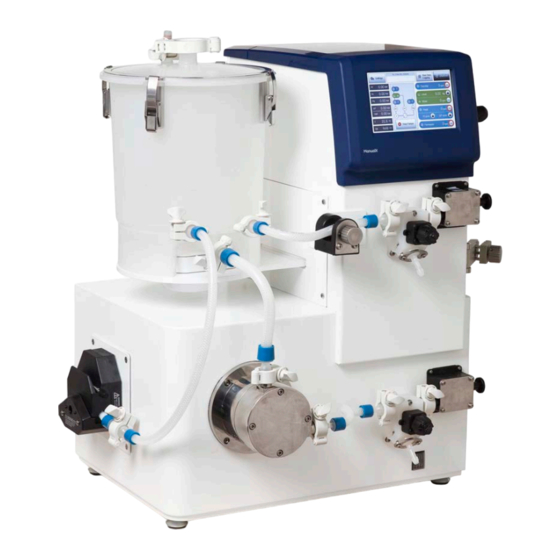
3 System description 3.1 Illustrations of ÄKTA flux 6 Illustrations of ÄKTA flux 6 Front view with all options Part Function Transfer pump (optional) Tank holder with tank balance and motor for mixer Tank Check valve Air filter Operator touchscreen Upper drain valve Retentate pressure sensor Pr ÄKTA flux 6 Operating Instructions 29046896 AE... - Page 26 3 System description 3.1 Illustrations of ÄKTA flux 6 Part Function Filter holder for hollow fiber cartridge. Hollow fiber cartridge shown. Retentate pressure control valve Feed pressure sensor Pf and temperature sensor Power switch Lower drain valve Feed pump Rear view with all options Part Function Permeate pressure control valve...
- Page 27 3 System description 3.1 Illustrations of ÄKTA flux 6 Part Function Permeate pressure sensor Pp (optional) Permeate pump (optional) USB-connector protection Ventilation holes for cabinet cooling fan Air inlet Circuit breakers Power cord connection and fuse drawer ÄKTA flux 6 Operating Instructions 29046896 AE...
-
Page 28: System Control
3 System description 3.2 System control System control Introduction ÄKTA flux 6 is controlled by a process and control software from a built-in computer. The computer starts automatically when the system power is turned on. Operator touchscreen The user interacts with the system from the touchscreen. System warnings and alarms are displayed, indicators show system status and commands are entered from a control panel. - Page 29 3 System description 3.2 System control Part Description Function Settings button Submenus: USB Device, Alarms, Configure, Calibration and System Information. Information panel Displays active automated functions and the settings for these. Start and Stop Data This function is active when a USB device is Logging connected.
- Page 30 3 System description 3.2 System control ÄKTA flux 6 Operating Instructions 29046896 AE...
- Page 31 3 System description 3.2 System control Control panel Part Description Function Transfer Adjusts the transfer pump (optional) and displays transfer pump rotation speed or flow rate. Level Adjusts level control and displays amount of fluid in the tank. Mixer Adjusts the mixer and displays rotational speed of the mixer.
- Page 32 3 System description 3.2 System control Button Description A Stop button with a surrounding green circle indicates that the Stop Start parameter is active. The Start button automatically changes to a Stop button when a Stop Start pump is started. Start A Start button with a surrounding red circle indicates the Stop Start...
- Page 33 3 System description 3.2 System control Process flowchart panel Part Function Transfer pump (optional) Mixer and tank Feed pump Feed pressure sensor (Pf) Temperature sensor Retentate pressure sensor (Pr) Filter Permeate pump (optional) Permeate pressure sensor (Pp) (optional) ÄKTA flux 6 Operating Instructions 29046896 AE...
- Page 34 3 System description 3.2 System control Indicators The process flowchart panel includes the following indicators: Indicator Description A blue circle around the motor symbol indicates that the pump is not running. A green circle around the motor symbol indicates that the pump is running. A yellow circle around the motor symbol indicates a pump warning.
- Page 35 3 System description 3.2 System control Parameter panel Part Symbol Function Displays feed pressure Displays retentate pressure Displays permeate pressure ΔP Displays Δpressure ΔP = Pf - Pr Displays transmembrane pressure TMP = [(Pf + Pr)/2] - Pp Displays system temperature Calculated permeate flow Stopping the process Button...
- Page 36 3 System description 3.2 System control Button Function The pumps can be stopped at any time by tapping the Stop Pumps button on the main screen. Stop Start All running pumps on the system will be stopped. A red circle will be shown on the Start button. Start Use the Stop Pumps button if the pumps needs to be stopped quickly during an unexpected...
-
Page 37: Standard Equipment
3 System description 3.3 Standard equipment Standard equipment Introduction This section provides an overview of the standard components of ÄKTA flux 6. In this section Section See page 3.3.1 Feed pump, pressure sensors and pressure control valve 3.3.2 Tank 3.3.3 Communication connection ÄKTA flux 6 Operating Instructions 29046896 AE... -
Page 38: Feed Pump, Pressure Sensors And Pressure Control Valve
3 System description 3.3 Standard equipment 3.3.1 Feed pump, pressure sensors and pressure control valve 3.3.1 Feed pump, pressure sensors and pressure control valve ÄKTA flux 6 feed pump The feed pump used in ÄKTA flux 6 is of the diaphragm type. Pressure sensors The feed pressure sensor, Pf, and the retentate pressure sensor, Pr, are both used in the recirculation loop, see... - Page 39 3 System description 3.3 Standard equipment 3.3.1 Feed pump, pressure sensors and pressure control valve Pressure control valves There are two pressure control valves installed on the instrument: • The retentate pressure control valve used in the retentate line enables manual regulation of the liquid flow by adjusting the pressure upstream the filter.
-
Page 40: Tank
3 System description 3.3 Standard equipment 3.3.2 Tank 3.3.2 Tank Illustration Part Description Air filter Check valve Tank lid Level indication Magnetic stir bar Retentate inlet Feed outlet Transfer inlet ÄKTA flux 6 Operating Instructions 29046896 AE... - Page 41 3 System description 3.3 Standard equipment 3.3.2 Tank Description ÄKTA flux 6 has an an eight liter tank. The tank has a feed outlet, transfer and retentate inlets. It is equipped with a check valve and an air filter. The volume in the tank is calculated on the basis of the weight. The weight is measured with a tank balance.
-
Page 42: Communication Connection
3 System description 3.3 Standard equipment 3.3.3 Communication connection 3.3.3 Communication connection USB connection The USB memory stick is used to save process data and produce a system health report. A protective cap is used to cover the USB memory stick. ÄKTA flux 6 Operating Instructions 29046896 AE... -
Page 43: Optional Equipment
3 System description 3.4 Optional equipment Optional equipment Introduction Optional pumps can be installed to transfer liquid to the tank and to control the permeate flow. A permeate pressure sensor can also be installed in the permeate line. A holder for Kvick Lab™ cassettes is an optional item. Transfer pump An optional transfer pump is available to set up the transfer line. -
Page 44: Filter Devices
3 System description 3.5 Filter devices Filter devices Introduction This section contains a description and an overview of the filter types that can be installed with ÄKTA flux 6: The following filter types can be used: • Hollow fiber cartridges •... -
Page 45: Hollow Fiber Cartridges
• Refer to operating handbook 18116530 for more information. • Refer to Method Handbook 29085076 for information about crossflow filtration. • Contact Cytiva for more information about other hollow fiber cartridges that can be used with ÄKTA flux 6. ÄKTA flux 6 Operating Instructions 29046896 AE... -
Page 46: Kvick Lab Cassette Holder Ii
3 System description 3.5 Filter devices 3.5.2 Kvick Lab Cassette Holder II 3.5.2 Kvick Lab Cassette Holder II Introduction Kvick Lab Cassette Holder II can be used with ÄKTA flux 6. It is recommended to use a maximum of three Kvick Lab cassettes although the holder can take up to five cassettes. - Page 47 • Refer to User Manual 18117169 for more information regarding Kvick Lab cassettes. • Refer to Method Handbook 29085076 for general information regarding crossflow filtration. • Contact Cytiva for more information about other filtration products that can be used with the ÄKTA flux 6. ÄKTA flux 6 Operating Instructions 29046896 AE...
-
Page 48: Flowchart
3 System description 3.6 Flowchart Flowchart Introduction This section contains a flowchart for ÄKTA flux 6. The process components and pres- sure sensors are listed. Flowchart illustration Black: standard components; Red: optional components Process components The following table lists the process components that are shown in the flowchart. Function Feed pump Lower drain valve... - Page 49 3 System description 3.6 Flowchart Function Tank Mixer Feed outlet from tank Tank transfer inlet Transfer pump (optional) External tank connection Filter feed inlet Filter retentate outlet Filter permeate outlet Permeate pressure sensor Pp (optional) Permeate pump (optional) Permeate outlet TC gasket positioning Drain Drain...
- Page 50 3 System description 3.6 Flowchart Function Product code TC-Gasket, 1 inch 29064009 TC-Gasket, 3/4 inch 29064008 TC-Gasket, 1/4 inch 29064007 ÄKTA flux 6 Operating Instructions 29046896 AE...
-
Page 51: Flow Lines
4 Flow lines Flow lines About this chapter This chapter provides an overview of the flow lines in ÄKTA flux 6. In this chapter Section See page Recirculation loop Permeate line Transfer line ÄKTA flux 6 Operating Instructions 29046896 AE... -
Page 52: Recirculation Loop
4 Flow lines 4.1 Recirculation loop Recirculation loop Introduction The recirculation loop consists of the feed line and the retentate line. Illustration Part Function Feed outlet from tank Feed pump Lower drain valve Feed pressure sensor Pf and temperature sensor Feed inlet to filter Retentate outlet from filter Retentate pressure sensor Pr... - Page 53 4 Flow lines 4.1 Recirculation loop Flow path The feed line transfers liquid from the tank to the filter via the feed pump. The retentate with particles or molecules too large to pass through the filter pores is returned to the tank via the retentate line.
-
Page 54: Permeate Line
4 Flow lines 4.2 Permeate line Permeate line Introduction The permeate line carries the permeate that exits the filter through the permeate outlet. Permeate flow control Liquid containing particles or molecules small enough to pass through the filter pores is collected as permeate. Permeate exits the filter through the permeate outlet on the filter. - Page 55 4 Flow lines 4.2 Permeate line Optional permeate equipment The permeate line can be equipped with a permeate pump and a pressure sensor. The permeate pump is used to control the permeate flow rate and the permeate pressure sensor, Pp, measures permeate pressure. Part Function Permeate pressure sensor inlet...
-
Page 56: Transfer Line
4 Flow lines 4.3 Transfer line Transfer line Introduction The transfer line requires the optional transfer pump. Illustration Part Function Transfer inlet to tank Transfer line Tubing outlet from transfer pump Transfer pump Description The transfer line transfers liquid from an external tank to the ÄKTA flux tank via the transfer pump. -
Page 57: Installation
5 Installation Installation About this chapter This chapter provides required information to enable users and service personnel to unpack, transport, install and setup ÄKTA flux 6. In this chapter Section See page Site requirements Unpack the ÄKTA flux 6 Transport Set up the ÄKTA flux 6 Installation test Precautions... -
Page 58: Site Requirements
5 Installation 5.1 Site requirements Site requirements Summary of requirements The following table gives a summary of power supply and environmental requirements. Parameter Requirement Supply voltage 100-120/220-240 V AC, ± 10% Phases Single phase (with 3P ground pole) Frequency 50 to 60 Hz Maximum power Nominally 400 W Grounding... -
Page 59: Unpack The Äkta Flux 6
• that all equipment is enclosed in the delivery box according to the packing list. • the equipment for any apparent damage and document carefully if found. If any equipment is missing or damages are found, contact Cytiva immediately. Delivery box ÄKTA flux 6 is shipped in a delivery box with the following dimensions and weight:... - Page 60 5 Installation 5.2 Unpack the ÄKTA flux 6 CAUTION Make sure that the system is placed on a stable flat bench with adequate space for ventilation. CAUTION Two persons are required to lift ÄKTA flux 6. Lift only in the bottom part of the system.
-
Page 61: Transport
5 Installation 5.3 Transport Transport Introduction This section outlines important information that must be considered when trans- porting ÄKTA flux 6. Moving ÄKTA flux 6 CAUTION Before moving ÄKTA flux 6 the following must be done: 1. Empty ÄKTA flux 6. 2. -
Page 62: Set Up The Äkta Flux 6
5 Installation 5.4 Set up the ÄKTA flux 6 Set up the ÄKTA flux 6 Introduction This section describes the steps that need to be taken to set up ÄKTA flux 6 before use. In this section Section See page 5.4.1 Power supply and USB connection 5.4.2... -
Page 63: Power Supply And Usb Connection
5 Installation 5.4 Set up the ÄKTA flux 6 5.4.1 Power supply and USB connection 5.4.1 Power supply and USB connection Power supply and fuses WARNING The supply voltage must correspond to the markings on the system. The illustration below shows the location of the power supply and fuses on the ÄKTA flux 6. - Page 64 5 Installation 5.4 Set up the ÄKTA flux 6 5.4.1 Power supply and USB connection Connect power supply WARNING ÄKTA flux 6 must always be connected to a grounded power outlet. WARNING Do not block access to the power switch and power cord. The power switch must always be easy to access.
- Page 65 5 Installation 5.4 Set up the ÄKTA flux 6 5.4.1 Power supply and USB connection USB connection CAUTION Make sure that the USB port is protected from moisture and liquid by always having a protective cap on. The protective cap for the USB memory stick is placed on the right side of ÄKTA flux 6 seen from the front.
-
Page 66: Install And Remove The Tank
5 Installation 5.4 Set up the ÄKTA flux 6 5.4.2 Install and remove the tank 5.4.2 Install and remove the tank Precautions WARNING Use fume mask during tank opening when processing hazardous liquids, to avoid possible exposure to aerosols. CAUTION Handle tank with care. -
Page 67: Tubing
5.4 Set up the ÄKTA flux 6 5.4.3 Tubing 5.4.3 Tubing Introduction ÄKTA flux 6 is delivered with necessary tubing for the recirculation loop. Other optional tubing is available from Cytiva. Precautions WARNING Use only approved tubing and components together with ÄKTA flux 6. CAUTION Changing of tubing exposes operator to residual fluid that might cause contamination of skin and clothing. - Page 68 5 Installation 5.4 Set up the ÄKTA flux 6 5.4.3 Tubing Tubing tags All tubing for the flow lines is tagged. The illustration below shows an example of a tubing tag. The characters on the tag are explained in the table. R1LH Locat Description...
- Page 69 5 Installation 5.4 Set up the ÄKTA flux 6 5.4.3 Tubing Tubing connections The illustration shows the tubing in the recirculation loop in ÄKTA flux 6. The tubing is connected with TC clamps and TC gaskets. R1LH F2LH Tubing The tubing in the table below are delivered with ÄKTA flux 6. Tubing Tubing size (inner diameter)
- Page 70 5 Installation 5.4 Set up the ÄKTA flux 6 5.4.3 Tubing Tubing Tubing size (inner diameter) Tubing to transfer pump inlet 6.4 mm Tubing from transfer tank outlet 6.4 mm Pump tubing for optional pumps 8.0 mm Low flow kit The low flow kit consists of the tubing listed in the table below.
- Page 71 5 Installation 5.4 Set up the ÄKTA flux 6 5.4.3 Tubing Tubing for Cleaning in Place (CIP) A T-piece is used for Cleaning in Place (CIP). It is attached with TC clamps and TC gaskets. For tubing tags, see table below. Part Description Tubing size...
-
Page 72: Install The Transfer Pump
5 Installation 5.4 Set up the ÄKTA flux 6 5.4.4 Install the transfer pump 5.4.4 Install the transfer pump Introduction This section describes how to install the optional transfer pump. Precautions WARNING Disconnect power to the product before installation of the optional pump. - Page 73 5 Installation 5.4 Set up the ÄKTA flux 6 5.4.4 Install the transfer pump Install the transfer pump Follow the steps below to install the transfer pump. Step Action Disconnect the power. Unscrew the screws holding the casing for the transfer pump connections and remove the casing.
- Page 74 5 Installation 5.4 Set up the ÄKTA flux 6 5.4.4 Install the transfer pump Step Action Connect the power cable to the corresponding connection on the transfer pump. Attach the pump to ÄKTA flux 6 and make sure that the fittings for the screws on the chassis match the ones on the transfer pump.
- Page 75 5 Installation 5.4 Set up the ÄKTA flux 6 5.4.4 Install the transfer pump Step Action Fasten the screws. When the transfer pump is installed, perform the following actions: • Perform a motor control, see Motor control on page 121. •...
-
Page 76: Install The Permeate Pump
5 Installation 5.4 Set up the ÄKTA flux 6 5.4.5 Install the permeate pump 5.4.5 Install the permeate pump Introduction This section describes how to install the optional permeate pump. Precautions WARNING Disconnect power to the product before installation of the optional pump. - Page 77 5 Installation 5.4 Set up the ÄKTA flux 6 5.4.5 Install the permeate pump Step Action Unscrew the screws holding the casing for the permeate pump connections and remove the casing. Pull out the power and communication cables. ÄKTA flux 6 Operating Instructions 29046896 AE...
- Page 78 5 Installation 5.4 Set up the ÄKTA flux 6 5.4.5 Install the permeate pump Step Action Connect the communication cable to the corresponding connection on the permeate pump. Connect the power cable to the corresponding connection on the permeate pump. ÄKTA flux 6 Operating Instructions 29046896 AE...
- Page 79 5 Installation 5.4 Set up the ÄKTA flux 6 5.4.5 Install the permeate pump Step Action Attach the pump to ÄKTA flux 6 and make sure that the fittings for the screws on the chassis match the ones on the permeate pump. Fasten the screws.
-
Page 80: Install The Permeate Pressure Sensor
5 Installation 5.4 Set up the ÄKTA flux 6 5.4.6 Install the permeate pressure sensor 5.4.6 Install the permeate pressure sensor Introduction This section describes how to install the optional permeate pressure sensor. Precautions Disconnect power to ÄKTA flux 6 before installation of the permeate pressure sensor. Tools required A T20 Torx™... - Page 81 5 Installation 5.4 Set up the ÄKTA flux 6 5.4.6 Install the permeate pressure sensor Step Action Connect the power and communication cable to the connection on the pres- sure sensor. Place the pressure sensor over the fittings for the screws on the chassis so that they match.
- Page 82 5 Installation 5.4 Set up the ÄKTA flux 6 5.4.6 Install the permeate pressure sensor Step Action Fasten the screws. Calibrate the pressure sensor using the supplied factory settings. ÄKTA flux 6 Operating Instructions 29046896 AE...
-
Page 83: Pump Tubing
5 Installation 5.4 Set up the ÄKTA flux 6 5.4.7 Pump tubing 5.4.7 Pump tubing Connect the pump tubing WARNING Disconnect power to the product before installing the pump tubing. Follow the instructions below to connect the pump tubing on the optional pumps. Step Action Rotate the lever to the left to open the pump. - Page 84 5 Installation 5.4 Set up the ÄKTA flux 6 5.4.7 Pump tubing Step Action Rotate the lever to the right to close. ÄKTA flux 6 Operating Instructions 29046896 AE...
-
Page 85: Installation Test
5 Installation 5.5 Installation test Installation test Performance The following performance tests must be done after installation: • Feed pump motor control, see Motor control on page 121. • Tank level calibration, refer to Calibrate the tank level, on page 122. -
Page 86: Run Preparations
6 Run preparations Run preparations About this chapter This chapter provides the information required to prepare ÄKTA flux 6 for operation. Before ÄKTA flux 6 is taken into operation, make sure that all procedures in the following chapter and section have been performed: •... -
Page 87: Filter Installation
6 Run preparations 6.1 Filter installation Filter installation Precautions WARNING Make sure that the filter is installed according to instructions for use of the filter. WARNING Before connecting the filter to ÄKTA flux 6, read the instructions for use of the filter. To avoid exposing the filter to excessive pressure, make sure that the pressure limit is set to the specified maximum pressure of the filter. - Page 88 6 Run preparations 6.1 Filter installation Using the P1L tubing If the permeate control valve is used on the permeate side, the P1L tubing is connected to the permeate filter outlet. The descriptions on the following pages refer to installations with the optional permeate pressure sensor and the permeate pump installed.
-
Page 89: Filtration Tubing
6 Run preparations 6.1 Filter installation 6.1.1 Filtration tubing 6.1.1 Filtration tubing All tubing for the flow lines is tagged. The illustration below shows an example of a tubing tag. The characters on the tag are explained in the table below. Location Description Length... -
Page 90: Install Hollow Fiber Cartridges
6 Run preparations 6.1 Filter installation 6.1.2 Install hollow fiber cartridges 6.1.2 Install hollow fiber cartridges The filter tubing listed below can be used with 3M hollow fiber cartridges and ÄKTA flux 6. Part Description FF2L From feed pressure sensor to filter FF6L From filter to retentate pressure sensor From filter to permeate pressure sensor... - Page 91 6 Run preparations 6.1 Filter installation 6.1.2 Install hollow fiber cartridges 3x2M The filter tubing listed below can be used with 3x2M hollow fiber cartridges and ÄKTA flux 6. Part Description FF2L From feed pressure sensor to filter FF9L From filter to retentate pressure sensor From filter to permeate pressure sensor If the optional permeate pressure sensor and permeate pump not are installed the tubing P1L is to be attached on the filter permeate outlet.
- Page 92 6 Run preparations 6.1 Filter installation 6.1.2 Install hollow fiber cartridges The filter tubing listed below can be used with 4M hollow fiber cartridges and ÄKTA flux 6. Part Description FF2L From feed pressure sensor to filter FF6L From filter to retentate pressure sensor From filter to permeate pressure sensor If the optional permeate pressure sensor and permeate pump not are installed the tubing P1L is to be attached on the filter permeate outlet.
- Page 93 6 Run preparations 6.1 Filter installation 6.1.2 Install hollow fiber cartridges 4x2M The filter tubing listed below can be used with 4x2M hollow fiber cartridges and ÄKTA flux 6. Part Description FF2L From feed pressure sensor to filter FF9L From filter to retentate pressure sensor From filter to permeate pressure sensor If the optional permeate pressure sensor and permeate pump not are installed the tubing P1L is to be attached on the filter permeate outlet.
- Page 94 6 Run preparations 6.1 Filter installation 6.1.2 Install hollow fiber cartridges The filter tubing listed below can be used with AXM hollow fiber cartridges and ÄKTA flux 6. Part Description FF1L From feed pressure sensor to filter FF7L From filter to retentate pressure sensor From filter to permeate pressure sensor If the optional permeate pressure sensor and permeate pump not are installed the tubing P1L is to be attached on the filter permeate outlet.
- Page 95 6 Run preparations 6.1 Filter installation 6.1.2 Install hollow fiber cartridges Step Action Prepare and check the HF cartridges according to the manufacturer´s instructions. Attach the HF cartridges on the filter holder. Connect the feed pressure sensor outlet to the feed inlet on the filter. Connect the retentate outlet filter to the retentate pressure sensor inlet.
-
Page 96: Install Kvick Lab Cassettes
6 Run preparations 6.1 Filter installation 6.1.3 Install Kvick Lab cassettes 6.1.3 Install Kvick Lab cassettes Precautions CAUTION Because of the weight of the KvickLab Cassette Holder ll, great care must be taken not to cause squeezing or crushing injuries during movement. - Page 97 6 Run preparations 6.1 Filter installation 6.1.3 Install Kvick Lab cassettes Part Description FF2L From feed pressure sensor to filter FF3L From filter to retentate pressure sensor From filter to permeate pressure sensor If the optional permeate pressure sensor and permeate pump not are installed the tubing P1L is to be attached on the filter permeate outlet.
- Page 98 6 Run preparations 6.1 Filter installation 6.1.3 Install Kvick Lab cassettes Step Action Connect the Retentate outlet (2) to the retentate pressure sensor inlet using a TC gasket and a TC clamp. Connect the Permeate outlet (3) to the permeate filter inlet using a TC gasket and a TC clamp.
-
Page 99: Testing Filters
It is recommended to perform a filter integrity test on each filter before usage. Perform tests according to the filter manufacturer’s instructions. This is usually some form of air diffusion test using a water wetted filter. Refer to Cytiva integrity test guides 18117269 or 18117173, or your filter manufacturer's instructions. -
Page 100: Calibration
6 Run preparations 6.3 Calibration Calibration Introduction This section describes the procedures used to perform calibration of the pumps and other parts in ÄKTA flux 6. When to use these procedures It is recommended to perform calibrations before each run. Allowed user performed calibrations: •... -
Page 101: Calibration Of The Feed Pump
6 Run preparations 6.3 Calibration 6.3.1 Calibration of the feed pump 6.3.1 Calibration of the feed pump Follow the instructions below to calibrate the system flow for the feed pump. Step Action Put a stopper (1) in the transfer inlet to the tank. Fill the tank with water (2). - Page 102 6 Run preparations 6.3 Calibration 6.3.1 Calibration of the feed pump Step Action Set a low RPM value of the feed pump on the control panel and tap Start. Let the pump run for a couple of minutes. Fill more water in the tank, if needed. For an instruction how to use set-points, see Adjust set-points, on page 156.
- Page 103 6 Run preparations 6.3 Calibration 6.3.1 Calibration of the feed pump Step Action Remove the tubing from beaker A and put it in beaker B. Collect water between time point 0 and time point T, where T is at least one minute. Measure the mass of the water in beaker B with an external balance and calculate the flow rate (weight/time).
- Page 104 6 Run preparations 6.3 Calibration 6.3.1 Calibration of the feed pump Step Action Tap Feed pump on the Calibration Settings screen. Enter the low RPM value of the feed pump and the corresponding calculated flow value in the gray field indicated with .
- Page 105 6 Run preparations 6.3 Calibration 6.3.1 Calibration of the feed pump Step Action Enter the high RPM value of the feed pump and the corresponding calcu- lated flow value in the gray field indicated with Enter the saved Pf feed pressure sensor value measured in the gray field marked with Pressure.
- Page 106 6 Run preparations 6.3 Calibration 6.3.1 Calibration of the feed pump Step Action Tap Enter. Result: The software calculates the correlation between used RPM and achieved flow and the feed pump is calibrated. Note: If the optional pump tubing is changed the pump calibration needs to be repeated.
-
Page 107: Calibration Of The Transfer Pump
6 Run preparations 6.3 Calibration 6.3.2 Calibration of the transfer pump 6.3.2 Calibration of the transfer pump Normally the transfer pump is calibrated at a back pressure of 0 Bar. If the transfer pump is to be calibrated at another back pressure, an external pressure sensor must be used together with a pinch to apply the back pressure. - Page 108 6 Run preparations 6.3 Calibration 6.3.2 Calibration of the transfer pump Step Action Set a low RPM value of the transfer pump on the control panel and tap Start. Let the pump run for a couple of minutes. For an instruction how to use set-points, see Adjust set-points, on page 156.
- Page 109 6 Run preparations 6.3 Calibration 6.3.2 Calibration of the transfer pump Step Action Move the tubing connected to the transfer pump outlet, from beaker A to beaker B (empty beaker), and start to collect flow at the transfer pump outlet. Collect fluid between time point 0 and time point T.
- Page 110 6 Run preparations 6.3 Calibration 6.3.2 Calibration of the transfer pump Step Action Tap Calibration on the screen that appears. Tap Transfer pump on the Calibration Settings screen. Enter the low RPM value of the transfer pump and the corresponding calcu- lated flow value in the gray field indicated with .
- Page 111 6 Run preparations 6.3 Calibration 6.3.2 Calibration of the transfer pump Step Action Enter the high RPM value of the transfer pump and the corresponding calcu- lated flow value in the gray field indicated with The transfer pump is calibrated at 0 bar back pressure. ÄKTA flux 6 Operating Instructions 29046896 AE...
- Page 112 6 Run preparations 6.3 Calibration 6.3.2 Calibration of the transfer pump Step Action Tap Enter. Result: The software calculates the correlation between used RPM and achieved flow and the transfer pump is calibrated. To see the flow in mL/min on the main screen after calibration, set the flow rate for the transfer pump to mL/min, see Set units, on page 148.
-
Page 113: Calibration Of The Permeate Pump
6 Run preparations 6.3 Calibration 6.3.3 Calibration of the permeate pump 6.3.3 Calibration of the permeate pump Follow the instructions below to calibrate the system flow for the permeate pump. The permeate pump is optional. Step Action Connect tubing to the permeate pressure sensor inlet (1) and the permeate pump outlet (2). - Page 114 6 Run preparations 6.3 Calibration 6.3.3 Calibration of the permeate pump Step Action Set a low RPM value of the permeate pump on the control panel and tap Start. Let the pump run for a couple of minutes. For an instruction how to use set-points, see Adjust set-points, on page 156.
- Page 115 6 Run preparations 6.3 Calibration 6.3.3 Calibration of the permeate pump Step Action Move the tubing connected to the permeate pump outlet, from beaker A to beaker B (empty beaker), and start to collect flow at the permeate pump outlet in beaker B. Note the Pp permeate pressure sensor value shown on the indicator panel.
- Page 116 6 Run preparations 6.3 Calibration 6.3.3 Calibration of the permeate pump Step Action Tap Permeate pump on the Calibration Settings screen. Enter the low RPM value of the permeate pump and the corresponding calculated flow value in the gray field indicated with .
- Page 117 6 Run preparations 6.3 Calibration 6.3.3 Calibration of the permeate pump Step Action Enter the high RPM value of the permeate pump and the corresponding calculated flow value in the gray field indicated with Enter the saved Pp permeate pressure sensor value in the gray field marked with Pressure.
- Page 118 6 Run preparations 6.3 Calibration 6.3.3 Calibration of the permeate pump Step Action Tap Enter. Result: The software calculates the correlation between used RPM and achieved flow and the permeate pump is calibrated. To see the flow in mL/min on the main screen after calibration, set the flow rate for the permeate pump to mL/min, see Set units, on page 148.
-
Page 119: Calibration Of The Pressure Sensors
Result: The permeate pressure factory calibration settings for the installed unit are applied to system. Calibrate pressure sensors Contact Cytiva for a full-range calibration for the following sensors: • Feed pressure sensor Pf ÄKTA flux 6 Operating Instructions 29046896 AE... - Page 120 6 Run preparations 6.3 Calibration 6.3.4 Calibration of the pressure sensors • Permeate pressure sensor Pp • Retentate pressure sensor Pr ÄKTA flux 6 Operating Instructions 29046896 AE...
-
Page 121: Motor Control
6 Run preparations 6.3 Calibration 6.3.5 Motor control 6.3.5 Motor control A motor control calibration is performed in order to recognize which motors that are connected to the system and shall always be performed when the optional transfer or permeate pump is installed. Follow the instructions below to perform the motor control. -
Page 122: Tank Level
6 Run preparations 6.3 Calibration 6.3.6 Tank level 6.3.6 Tank level Tank balance It is recommended to calibrate the tank balance prior to each run to obtain a reliable output. The tank balance must also be calibrated every time the system has been moved, or if there has been any interference with the balance. - Page 123 6 Run preparations 6.3 Calibration 6.3.6 Tank level Step Action Tap the gray field indicated with in Step #1: panel. Tap Enter in Step #1: panel for zero point calibration. Fill in the tank with a known mass of water measured from a measuring jar. in Step #2: panel.
-
Page 124: Operation
7 Operation Operation About this chapter This chapter provides the information required to operate ÄKTA flux 6 in a safe way. In this chapter Section See page Start the system Perform a run Procedures after the run Precautions WARNING Before performing any of the procedures described in this chapter, you must read and understand all contents of the corresponding sections in Chapter 2 Safety instructions, on page... -
Page 125: Start The System
• Maintenance and pump tubing replacement of the ÄKTA flux 6 must be scheduled on regular basis with a Cytiva representative and performed by properly trained personnel only. • Always use appropriate Personal Protective Equipment (PPE) when operating and interacting with ÄKTA flux 6. - Page 126 7 Operation 7.1 Start the system Final checks before start NOTICE Make sure that the actions listed below are completed before ÄKTA flux 6 is started. • Check that there is process liquid in the tank. • Check that all inlets and outlets to the system are connected, closed or in appro- priate state depending on the designed process.
-
Page 127: Perform A Run
7 Operation 7.2 Perform a run Perform a run Precautions WARNING Never block the outlet tubing and/or the check valves outlet with, for example, stop plugs, since this will create overpressure or hard- ware failure and can result in injury. WARNING Hot circulating fluids in ÄKTA flux 6 can cause hot fluidic lines, hot tank and hot chassis components. - Page 128 7 Operation 7.2 Perform a run In this section Section See page 7.2.1 Basic filtration 7.2.2 Automated features 7.2.3 Data logging 7.2.4 Shutdown ÄKTA flux 6 ÄKTA flux 6 Operating Instructions 29046896 AE...
-
Page 129: Basic Filtration
7 Operation 7.2 Perform a run 7.2.1 Basic filtration 7.2.1 Basic filtration Follow the steps below to perform a basic filtration. Step Action Fill the tank. Tap Mixer (1) on the control panel. Use the displayed keypad to set the desired mixer speed (rpm) and tap OK. For an instruction how to use set-points, see Adjust set-points, on page 156. -
Page 130: Automated Features
7 Operation 7.2 Perform a run 7.2.2 Automated features 7.2.2 Automated features Constant retentate volume The transfer pump and the level function can be used to keep a constant retentate volume (CRV) in the tank. To do this, follow the steps below. Note: It is not recommended to use the CRV function with low volume in the the tank (<... - Page 131 7 Operation 7.2 Perform a run 7.2.2 Automated features Step Action Tap Start (2) to activate the mixer. Result: Level will control start and stop the transfer pump to keep the level of the tank constant. To stop the function, tap Lock button and use the displayed keypad to tap Deactivate.
- Page 132 7 Operation 7.2 Perform a run 7.2.2 Automated features ΔP auto The delta pressure, measured by the feed and retentate pressure sensors, can be used to control the feed flow rate. To do this, follow the steps below. Auto delta pressure works between feed flow rate from 0.4 l/min to 6 l/min with toler- ance of +/- 0.3 bar.
- Page 133 7 Operation 7.2 Perform a run 7.2.2 Automated features Constant permeate flow The following steps require that the optional permeate pump is installed. Make sure that the feed pump is running at stable conditions before starting the permeate pump. To do this, follow the steps below. Step Action Tap Permeate (1) on the control panel.
-
Page 134: Data Logging
7 Operation 7.2 Perform a run 7.2.3 Data logging 7.2.3 Data logging USB memory stick Data in a run can be captured on a USB memory stick. The file format is CSV (Comma ® ® Separated Value). The format CSV can be read by Microsoft Excel , for example. - Page 135 7 Operation 7.2 Perform a run 7.2.3 Data logging Step Action Tap Eject USB. Note: The data can be lost if this step is ignored. Manually disconnect the USB memory stick from ÄKTA flux 6. Save the result file To save the result file, follow the steps below. Step Action Insert the USB memory stick in the computer.
-
Page 136: Shutdown Äkta Flux 6
7 Operation 7.2 Perform a run 7.2.4 Shutdown ÄKTA flux 6 7.2.4 Shutdown ÄKTA flux 6 To shut down the system, follow the steps below. Step Action Tap Shutdown on the main screen. Tap Yes to power off the instrument. Note: If a restart of the system is required, tap Restart and do not proceed to step Turn off the instrument by pushing the power switch to the 0 position when... -
Page 137: Procedures After The Run
7 Operation 7.3 Procedures after the run Procedures after the run Introduction The procedures after the run must be performed in the following order: 1. Empty the system. 2. Clean the system and filters after every run. 3. Prepare ÄKTA flux 6 for storage. Precautions CAUTION Let the ÄKTA flux 6 cool down after use as the components and... - Page 138 7 Operation 7.3 Procedures after the run Prepare for storage If desired, prepare the system for storage as described in Section 9.3 Storage, on page 167. ÄKTA flux 6 Operating Instructions 29046896 AE...
-
Page 139: Settings
8 Settings Settings About this chapter This chapter describes the submenus in Settings. It also includes a description on how to change the settings of the parameters. In this chapter Section See page USB Device Management screen and software update Configure Alarms screen Configure System screen Calibration Settings screen... -
Page 140: Usb Device Management Screen And Software Update
8 Settings 8.1 USB Device Management screen and software update USB Device Management screen and software update USB storage device panel The USB Storage Device panel shows if a USB memory stick is connected to the system, information about the type of USB memory stick and the storage capacity are displayed on the USB Storage Device panel. - Page 141 8 Settings 8.1 USB Device Management screen and software update Step Action Tap Generate Report. Result: A text file is created onto the USB memory stick. Tap Eject USB. Remove the USB memory stick from the USB port. Software update The steps below explain how to upgrade software or install software.
- Page 142 8 Settings 8.1 USB Device Management screen and software update Step Action In the USB Device Management screen select Update Software. Select Yes. Wait for software to update and for the application to restart. Navigate to Settings →USB Device →USB Device Management. Select Eject USB.
-
Page 143: Configure Alarms Screen
8 Settings 8.2 Configure Alarms screen Configure Alarms screen Precautions WARNING All alarm signals must be set within the limits specified in the system documentation. Pressure and temperature control must be activated while the system is in use to prevent the tubing system to leak or break. - Page 144 8 Settings 8.2 Configure Alarms screen See the table below for an overview of the possible alarm or warning settings of each parameter. Parameter Alarm Alarm Warning Warning High High Feed pressure Retentate pressure Permeate pressure Temperature Permeate Flow Rate Permeate Flux Tank Level Note:...
- Page 145 8 Settings 8.2 Configure Alarms screen Part Function A green indicator shows that at least one high or low warning or alarm has been set for the parameter. A red indicator shows that an alarm or a warning is triggered. ÄKTA flux 6 Operating Instructions 29046896 AE...
- Page 146 8 Settings 8.2 Configure Alarms screen Set system alarm parameters The example below shows how the Alarm High is set for feed pressure. Step Action Tap Settings on the main screen. Tap Alarms to open Configure Alarms screen. Tap Feed Pressure on the right hand of the screen. Tap the Alarm High button and use the - or + to set the preferred values for Alarm High, or use the displayed keypad to set points.
- Page 147 8 Settings 8.2 Configure Alarms screen Step Action The Feed Pressure indicator turns green showing that an alarm high is trig- gered. Note: To deactivate an alarm or warning tap the activated alarm and check that the indicator turns white. ÄKTA flux 6 Operating Instructions 29046896 AE...
-
Page 148: Configure System Screen
8 Settings 8.3 Configure System screen Configure System screen System parameters User configuration of system parameter units is set from the Configure System screen. The following units can be configured: Parameter Units Pressure bar, psi Temperature Celsius, Fahrenheit Feed Pump RPM, l/min, Shear Rate Permeate Flux g/min, LMH... - Page 149 8 Settings 8.3 Configure System screen Step Action If Shear Rate is chosen as the unit for Feed Pump, you also have to set the values for Flow Rate (l/min), and the corresponding Shear Rate (values provided by the hollow fiber manufacturer). ÄKTA flux 6 Operating Instructions 29046896 AE...
- Page 150 8 Settings 8.3 Configure System screen Step Action Tap the Flow Rate (l/min) field and the Shear Rate field to set the preferred values with the displayed keypad. Digits can be deleted using the arrow sign button in the upper right corner of the keypad. Nominal cartridge feed flow rate and pressure drop as a function of shear rate Style...
- Page 151 8 Settings 8.3 Configure System screen Step Action If LMH is chosen as the unit for Permeate Flux, you also have to set the value for the Filter Area (cm Tap the Filter Area (cm ) field and use the keypad to set the preferred value.
-
Page 152: Calibration Settings Screen
8 Settings 8.4 Calibration Settings screen Calibration Settings screen All the pumps, the pressure sensors and the tank level can be calibrated from the Cali- bration Settings screen. For information on how to perform calibration in ÄKTA flux 6, Section 6.3 Calibration, on page 100 The illustration below is just an example of a calibration screen. -
Page 153: System Information Screen
8 Settings 8.5 System Information screen System Information screen System information The System Information panels provide information on the different parts of the system. See the screen and table below for descriptions. Part Function Description Instrument panel Provides information about installed software and the serial number of the system. - Page 154 8 Settings 8.5 System Information screen Part Function Description System Up Time and Shows the system up time and the current Current System system time. Time panel Set System Time Sub-menu to set the system date and time, see button instructions below.
- Page 155 8 Settings 8.5 System Information screen Step Action Use the keypad that appears to enter new values. Digits can be deleted using the arrow sign button in the upper right corner of the keypad. Tap OK. Tap Cancel to close the keypad set without saving. ÄKTA flux 6 Operating Instructions 29046896 AE...
-
Page 156: Set-Points
8 Settings 8.6 Set-points Set-points Introduction This section describes how to enter set-points for Transfer, Level, Mixer, Feed, Pf auto, ΔP auto, and Permeate. Adjust set-points Follow the steps below to adjust the set-points. Step Action On the main screen, tap the parameter you want to set, for instance Transfer. - Page 157 8 Settings 8.6 Set-points Step Action Alternatively, tap the gray field and set the preferred values by using the displayed keypad. Digits can be deleted using the arrow sign button in the upper right corner of the keypad. Tap OK to save the settings. Tap Cancel to close the keypad without saving.
- Page 158 8 Settings 8.6 Set-points Step Action Enter the time interval and tap OK. A run report will be of recorded at the selected log interval. ÄKTA flux 6 Operating Instructions 29046896 AE...
-
Page 159: Maintenance
9 Maintenance Maintenance About this chapter This chapter provides required information to enable users and service personnel to maintain ÄKTA flux 6. In this chapter Section See page User maintenance schedule Sanitization and cleaning Storage Repair and calibration Replace mains fuse Precautions WARNING Before performing any of the procedures described in this chapter,... - Page 160 WARNING Before maintenance/service is performed, the system owner must first clean the system and complete a Health & Safety Declaration Form. Contact Cytiva for further information. ÄKTA flux 6 Operating Instructions 29046896 AE...
-
Page 161: User Maintenance Schedule
WARNING Use only approved parts. Only spare parts and accessories that are approved or supplied by Cytiva may be used for maintaining or servicing the product. For each run This section covers maintenance actions required for each run or weekly (depending on which happens first). - Page 162 Complete system A preventive maintenance test procedure on all systems, sensors, pumps and valves should be performed annually by trained and certified personnel. Contact your local Cytiva representative. Replace all gaskets, O-rings, and valve or pressure sensor diaphragms. Pump of Replace all wear and tear parts.
-
Page 163: Sanitization And Cleaning
9 Maintenance 9.2 Sanitization and cleaning Sanitization and cleaning General A suitable frequency of routine cleaning is determined by the nature of the starting material and the type of process. However, routine cleaning shall be performed at intervals aimed at prevention rather than cleaning ÄKTA flux 6 (and connected equip- ment) from growth or contamination. - Page 164 9 Maintenance 9.2 Sanitization and cleaning Follow the steps below to perform a CIP procedure. Step Action To enable CIP feature, tap CIP on the Configure System screen. The feed pump speed can be altered for CIP if required. Refer section [6.3.1] ÄKTA flux 6 Operating Instructions 29046896 AE...
- Page 165 9 Maintenance 9.2 Sanitization and cleaning Step Action Tap Start and confirm with Yes to start the feed pump . Note: The feed pump will reach the maximum speed of 1600 rpm within 1 minute when CIP is enabled. Under normal conditions the feed pump speed is 1200 rpm or 6 l/min.
- Page 166 9 Maintenance 9.2 Sanitization and cleaning For more information about cleaning of filters refer to: • Hollow fiber cartridges cleaning procedures are provided in the operating handbook 18116530, • Kvick Lab cassettes cleaning procedures are provided in User Manual 18117169, •...
-
Page 167: Storage
9 Maintenance 9.3 Storage Storage Introduction This section describes the procedures for storage of ÄKTA flux 6. Precautions NOTICE Fit protective caps on all electrical and optical connectors when not in use. NOTICE When the product is filled with a storage solution, the temperature must be high enough to prevent freezing, and low enough to prevent evaporation. - Page 168 9 Maintenance 9.3 Storage Step Action Release the tubing from the transfer and permeate pump heads by moving the lever from right to left, if these optional pumps are installed. Long term storage To prevent microbial growth, the storage solution must be replaced regularly if ÄKTA flux 6 is stored for long periods of time.
-
Page 169: Repair And Calibration
WARNING Do not attempt to perform any actions not described in this docu- ment. Always contact your Cytiva representative for advice if such a need should arise. Filter integrity test This method can be used to check that the filter is not damaged and that it has been mounted correctly. -
Page 170: Replace Mains Fuse
Replace mains fuse Introduction A blown fuse might indicate the existence of another problem in the instrument. If a replacement fuse blows, do not replace it. Contact your Cytiva representative. Precautions WARNING Always disconnect power to ÄKTA flux 6 before replacing fuses. - Page 171 9 Maintenance 9.5 Replace mains fuse Step Action Grip the fuse drawer and loosen it. ÄKTA flux 6 Operating Instructions 29046896 AE...
- Page 172 9 Maintenance 9.5 Replace mains fuse Step Action Fold the drawer lid to locate the mains fuses. Remove the old fuse with help of a small screwdriver that is inserted in the hole under the fuse drawer. Insert the new fuses. For specification of the fuses, see Electric power, on page 178.
- Page 173 9 Maintenance 9.5 Replace mains fuse Step Action Push the fuse drawer in its holder. ÄKTA flux 6 Operating Instructions 29046896 AE...
-
Page 174: 10 Troubleshooting
This chapter provides information for users and service personnel to identify and correct problems that might occur when operating ÄKTA flux 6. If the suggested actions in this guide do not solve the problem or if the problem is not covered by this guide then contact Cytiva for advice. Precautions WARNING... - Page 175 An automatic circuit • Turn off the instrument and visually inspect for breaker has triggered damage. If damaged then contact Cytiva. • Check if any of the automatic fuses has popped out and push them back in. A replaceable fuse has •...
-
Page 176: 11 Reference Information
11 Reference information 11 Reference information About this chapter This chapter provides useful reference information for installing, operating, main- taining and, troubleshooting ÄKTA flux 6. In this chapter Section See page 11.1 Specifications 11.2 Filter specifications 11.3 Wetted materials 11.4 Chemical resistance 11.5 Recycling information... -
Page 177: 11.1 Specifications
11 Reference information 11.1 Specifications 11.1 Specifications Dimensions All dimensions are presented in cm. Dimensions Value Length (bottom part) 53 cm Length (including filter holder) 64 cm Width (bottom part) 37 cm Width (including feed pump) 47 cm Height (including feet) 72 cm Height (feet) 2 cm... - Page 178 11 Reference information 11.1 Specifications System sound levels Properties Value 75 dBA Typical value under normal 65 dBA running conditions Electric power Property Value Supply voltage 100-120/220-240 V AC ±10%, 50 to 60 Hz Phases Single Max power 400 VA Ingress protection IP 21 Fuses...
- Page 179 11 Reference information 11.1 Specifications Parts and properties Value Temperature, storage -25°C to 50°C Temperature gradients of ≤ ±1°C/min Dry instrument (drained fluid path) Air humidity Max. relative humidity 80% for temperatures up to 31°C, decreasing linearity to 50% relative humidity at 40°C Altitude Max 2000 m Liquid temperature...
-
Page 180: 11.2 Filter Specifications
11 Reference information 11.2 Filter specifications 11.2 Filter specifications Hollow fiber HF filters Fitting type 1/2" TC 3x2M 1/2" TC 1/2" TC 4x2M 1/2" TC UNF 5/16" female Membrane cassette Holder type Cassette types Cassette size Number of Nut torque Fitting type cassettes Kvick Lab... -
Page 181: 11.3 Wetted Materials
11 Reference information 11.3 Wetted materials 11.3 Wetted materials Materials used The materials used in the manufacturing of ÄKTA flux 6 have been chosen for their biological and chemical compatibility with the solvents used during operation. List of wetted materials The table below lists the materials that come into contact with process fluids in ÄKTA flux 6. - Page 182 11 Reference information 11.3 Wetted materials Flow path scheme all components The following illustration shows an overview of the flow between different components in the ÄKTA flux 6. Blue tubing lines are included in the standard instrument, while gray tubing lines are optional. Equipment connected to gray tubing is optional. R1LH F2LH ÄKTA flux 6 Operating Instructions 29046896 AE...
- Page 183 11 Reference information 11.3 Wetted materials Tank assembly ÄKTA flux 6 Operating Instructions 29046896 AE...
- Page 184 11 Reference information 11.3 Wetted materials Drain valve parts Pressure sensor ÄKTA flux 6 Operating Instructions 29046896 AE...
- Page 185 11 Reference information 11.3 Wetted materials Feed pump parts 4:1 4:2 4:5 4:6 Standard components The tables below list the materials that come into contact with process fluids in ÄKTA flux 6. The product codes in the table below correspond to the numbers in the illustration above.
- Page 186 11 Reference information 11.3 Wetted materials Part Component Materials Feed pump Pump housing Stainless steel 316L (1.4404) O-Ring EPDM Valve housing Valve EPDM Piston Stainless steel 316L (1.4404) Diaphragm Santoprene Pump tubing Bioprene Transfer and permeate pump tubing Standard tubing, see Standard tubing, on page 186.
- Page 187 11 Reference information 11.3 Wetted materials Part Component Materials Fitting Circular Sealing Washer Platinum cured silicone Circular Sealing Washer Platinum cured silicone T-Fitting Optional tubing The optional tubing, gray in the illustration above, part number 10, include the following materials. Part Component Materials...
- Page 188 11 Reference information 11.3 Wetted materials Part Component Materials FF9H Tubing - filter out to retentate SBP Braid reinforced 3/8" ID FF3H Tubing - filter out to retentate SBP Braid reinforced 3/8" ID ÄKTA flux 6 Operating Instructions 29046896 AE...
-
Page 189: 11.4 Chemical Resistance
11 Reference information 11.4 Chemical resistance 11.4 Chemical resistance Introduction The tables below list allowed exposure concentrations and times for various chemicals that can be used for ÄKTA flux 6. WARNING Flammable liquids. ÄKTA flux 6 is not approved to handle flam- mable liquids. - Page 190 11 Reference information 11.4 Chemical resistance Allowed chemicals for wetted surfaces Chemical Concentration Max time / cycle Max acc. Usage expos. Acetic acid 3000 h Citric acid pH 2 to 2.5 1 h at temp ≤ 60°C 1000 h Ethanol 12 months Unlimited Storage...
- Page 191 11 Reference information 11.4 Chemical resistance Allowed chemicals for outer surfaces Chemical Concentration Acetic acid Ethanol Guanidine hydrochloride Hydrogen peroxide solution Minncare cold sterilant solution (fogging) 4,5% per-acetic acid and 22% hydrogen peroxide Minncare cold sterilant solution (Wiping) 3% Minncare solution Phosphoric acid 2-propanol Sodium chloride...
-
Page 192: 11.5 Recycling Information
11 Reference information 11.5 Recycling information 11.5 Recycling information Introduction This section describes the procedures for disposal and recycling of the ÄKTA flux 6. CAUTION Always use appropriate personal protective equipment when decommissioning the equipment. Decontamination The product must be decontaminated before decommissioning. All local regulations must be followed with regard to scrapping of the equipment. -
Page 193: 11.6 Regulatory Information
11 Reference information 11.6 Regulatory information 11.6 Regulatory information Introduction This section lists the directives and standards that are fulfilled by ÄKTA flux 6. In this section Section See page 11.6.1 Contact information 11.6.2 European Union and European Economic Area 11.6.3 Eurasian Economic Union Евразийский... -
Page 194: Contact Information
Manufacturing information The table below summarizes the required manufacturing information. Requirement Information Name and address of manufacturer Cytiva Sweden AB Björkgatan 30 SE 751 84 Uppsala Sweden Telephone number of manufacturer + 46 771 400 600 ÄKTA flux 6 Operating Instructions 29046896 AE... -
Page 195: European Union And European Economic Area
11 Reference information 11.6 Regulatory information 11.6.2 European Union and European Economic Area 11.6.2 European Union and European Economic Area Introduction This section describes regulatory information for the European Union and European Economic Area that applies to the equipment. Conformity with EU Directives See the EU Declaration of Conformity for the directives and regulations that apply for the CE marking. -
Page 196: Eurasian Economic Union
Presnenskaya nab., 10, fl. 12, pr. III, room 6 Telephone: + 7 495 739 6931 Fax nr: + 7 495 739 6932 E-mail: rucis@cytiva.com Информация о производителе и импортере В следующей таблице приводится сводная информация о производителе и импортере, согласно требованиям Технических регламентов Таможенного союза... - Page 197 Пресненская наб., д. 10, эт. 12, пом. III, ком. 6 Телефон: + 7 495 739 6931 Факс: + 7 495 739 6932 Адрес электронной почты: rucis@cytiva.com Description of symbol on the system label Описание обозначения на этикетке системы This Eurasian compliance mark indicates that the product is...
-
Page 198: Regulations For North America
Note: The user is cautioned that any changes or modifications not expressly approved by Cytiva could void the user’s authority to operate the equip- ment. This equipment has been tested and found to comply with the limits for a Class A digital device, pursuant to part 15 of the FCC Rules. -
Page 199: Regulatory Statements
11 Reference information 11.6 Regulatory information 11.6.5 Regulatory statements 11.6.5 Regulatory statements Introduction This section shows regulatory statements that apply to regional requirements. EMC emission, CISPR 11: Group 1, Class A statement NOTICE This equipment is not intended for use in residential environments and may not provide adequate protection to radio reception in such environments. -
Page 200: Declaration Of Hazardous Substances (Dohs)
11 Reference information 11.6 Regulatory information 11.6.6 Declaration of Hazardous Substances (DoHS) 11.6.6 Declaration of Hazardous Substances (DoHS) 根据 SJ/T11364-2014《电子电气产品有害物质限制使用标识要求》特提供如下 有关污染控制方面的信息。 The following product pollution control information is provided according to SJ/ T11364-2014 Marking for Restriction of Hazardous Substances caused by electrical and electronic products. - Page 201 11 Reference information 11.6 Regulatory information 11.6.6 Declaration of Hazardous Substances (DoHS) 有害物质的名称及含量 Name and Concentration of Hazardous Substances 产品中有害物质的名称及含量 Table of Hazardous Substances’ Name and Concentration 部件名称 有害物质 Compo- Hazardous substance nent name 铅 汞 镉 六价铬 多溴联苯 多溴二苯醚 (Pb) (Hg) (Cd)
-
Page 202: Other Regulations And Standards
11 Reference information 11.6 Regulatory information 11.6.7 Other regulations and standards 11.6.7 Other regulations and standards Introduction This section describes the standards that apply to the product. Biological and chemical compatibility The Wetted parts of the ÄKTA flux system/instrument/column meet the material requirements of the following standards and regulations: Requirement Description... -
Page 203: 11.7 Ordering Information
11 Reference information 11.7 Ordering information 11.7 Ordering information Introduction For ordering information, visit cytiva.com/aktaflux. ÄKTA flux 6 spare parts and accessories For correct up to date information on spare parts and accessories, visit cytiva.com/ aktaflux. ÄKTA flux 6 Operating Instructions 29046896 AE... -
Page 204: 11.8 Health And Safety Declaration Form
Service Ticket #: To make the mutual protection and safety of Cytiva service personnel and our customers, all equipment and work areas must be clean and free of any hazardous contaminants before a Service Engineer starts a repair. To avoid delays in the servicing of your equipment, complete this checklist and present it to the Service Engineer upon arrival. - Page 205 To make sure the mutual protection and safety of Cytiva personnel, our customers, transportation personnel and our environment, all equipment must be clean and free of any hazardous contaminants before shipping to Cytiva. To avoid delays in the processing of your equipment, complete this checklist and include it with your return.
-
Page 206: Index
Index Index Numerics Connections, 64 power supply, 64 3M, 90 Constant permeate flow, 133 3x2M, 91 Constant retentate volume, 56, 4M, 92 4x2M, 93 Cross flow filtration, 6 CRV, 130 CSV, 134, 140 Accessories, 203 Air filter, 25, 40, 48 Air inlet to cabinet, 27 Delivery box, 59 Alarms, 28, 144, 146... - Page 207 Index permeate line, 179 Ordering information, 203 transfer line, 179 Flowchart, 48 Fuse, 175 Parameters, 146, 148 Fuses, 27, 64, 170 alarms, 146 replace, 170 system parameters, 148 warnings, 146 Peristaltic pumps, 175 HF cartridge, 45 Permeate, 49, 54 HF cartridges, 94 recycling, 54 installation, 94 Permeate flow, 35...
- Page 208 Index Recycling, 192 tank lid, 40 Recycling information, 192 volume, 41 decontamination, 192 Tank balance, 25, 48 disposal of electrical compo- Tank holder, 25 nents, 192 Tank level, 122 Reference information, 176, 192 calibrate, 122 recycling, 192 Tank volume, 177 Regulatory information, 193 Temperature, 35 Repair, 169...
- Page 209 Page intentionally left blank...
- Page 210 © 2020 Cytiva All goods and services are sold subject to the terms and conditions of sale of the supplying company operating within the Cytiva business. A copy of those terms and conditions is available on request. Contact your local Cytiva representative for the most current information.
Need help?
Do you have a question about the AKTA flux 6 and is the answer not in the manual?
Questions and answers