Table of Contents
Advertisement
Advertisement
Table of Contents
Troubleshooting

Related Manuals for cytiva Xuri W25


Summary of Contents for cytiva Xuri W25
- Page 1 Xuri Cell Expansion System User Manual cytiva.com...
-
Page 2: Table Of Contents
Table of Contents Table of Contents Introduction ......................5 Important user information ........................6 About this manual ............................8 Associated documentation ........................9 Abbreviations ..............................10 System description .................... 11 System overview ............................12 Xuri Cell Expansion System W25 rocker ....................16 Xuri Cell Expansion W25 CBCU ....................... - Page 3 Table of Contents 4.5.2 O2 control mode ............................128 4.5.3 Speed control mode ............................ 130 4.5.4 O2/Speed control scheme ........................131 Media control ..............................132 4.6.1 Weight measurement ..........................133 4.6.2 Media addition ............................... 134 4.6.3 Perfusion ................................135 4.6.4 Deviation alarm .............................
- Page 4 Table of Contents 7.6.3 Troubleshooting Evaluation ........................241 Reference information ..................242 System specifications ..........................243 Component specifications ......................... 244 Client computer specifications ........................ 247 Chemical resistance ............................. 249 Control settings .............................. 250 8.5.1 Rocking control .............................. 251 8.5.2 Heating control .............................. 254 8.5.3 Gas flow control .............................
-
Page 5: Introduction
1 Introduction Introduction About this chapter This chapter includes important user information, intended use of the system, and lists of important concepts and user documentation. In this chapter Section See page Important user information About this manual Associated documentation Abbreviations Xuri Cell Expansion System W25 User Manual 29064622 AD... -
Page 6: Important User Information
1 Introduction 1.1 Important user information Important user information Read the Operating Instructions before operating the product All users must read the entire separate Operating Instructions before instal- ling, operating, or maintaining the product. Always keep the Operating Instructions at hand when operating the product. Do not operate the product in any other way than described in the user documenta- tion. - Page 7 1 Introduction 1.1 Important user information WARNING WARNING indicates a hazardous situation which, if not avoided, could result in death or serious injury. It is important not to proceed until all stated conditions are met and clearly understood. CAUTION CAUTION indicates a hazardous situation which, if not avoided, could result in minor or moderate injury.
-
Page 8: About This Manual
1 Introduction 1.2 About this manual About this manual Purpose of this manual The Xuri Cell Expansion System W25 User Manual provides you with instructions and information how to run Xuri Cell Expansion System W25. It also includes relevant guid- ance for practical handling and maintenance of the system units. -
Page 9: Associated Documentation
Associated documentation Introduction This section describes the user documentation that is delivered with the product, and how to find related literature that can be downloaded or ordered from Cytiva. User documentation for Xuri Cell Expansion System W25 The table below describes the user documentation for Xuri Cell Expansion System W25, which is available from the Help menu in UNICORN or on the user documenta- tion CD. -
Page 10: Abbreviations
1 Introduction 1.4 Abbreviations Abbreviations Introduction This section explains abbreviations that appear in the user documentation for this product. Abbreviations Concepts and abbreviations used in this manual are explained in the table below. Concept/abbreviation Explanation Cellbag™ bioreactor The disposable container in which the cells are cultured. -
Page 11: System Description
2 System description System description About this chapter This chapter gives an overview of Xuri Cell Expansion System W25 and describes the different bioreactor system units. In this chapter Section See page System overview Xuri Cell Expansion System W25 rocker Xuri Cell Expansion W25 CBCU Xuri Cell Expansion W25 Pump Cellbag bioreactor... -
Page 12: System Overview
(SCADA) system, such as the DeltaV™ control system, using the integrated OPC server. Contact Cytiva for instructions and guidance for OPC. Xuri Cell Expansion System W25 User Manual 29064622 AD... - Page 13 2 System description 2.1 System overview Illustration of the system The illustration below shows the main system units for use in single mode with one Xuri Cell Expansion W25 Pump . Dual mode uses two Xuri Cell Expansion W25 CBCU units for controlling the two Cellbag bioreactors independently.
- Page 14 2 System description 2.1 System overview Illustration of wave motion Stage Description Inflowing gas from the CBCU enters the Cellbag bioreactor through the inlet vent filter. The gas flow inflates the bag and oxygenates the culture. Metabolic waste gases leave the Cellbag bioreactor through the outlet vent filter.
- Page 15 2 System description 2.1 System overview Available controlled parameters The table below describes the controlled parameters for the fully configured bioreactor system. The controlled parameters of your configuration may vary from the list below. In dual mode, all parameters except rocking speed, angle and motion may be controlled independently in the two Cellbag bioreactors.
-
Page 16: Xuri Cell Expansion System W25 Rocker
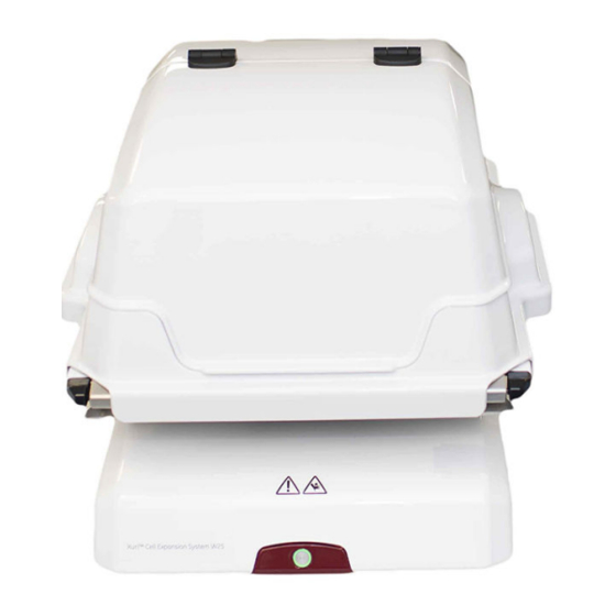
2 System description 2.2 Xuri Cell Expansion System W25 rocker Xuri Cell Expansion System W25 rocker Introduction The rocker is the main unit of the system. Through the rocker, weight is measured, and temperature, rocking speed, rocking angle and rocking motion are controlled. The rocker contains four load cells for monitoring the weight of the Cellbag bioreactor and content. - Page 17 2 System description 2.2 Xuri Cell Expansion System W25 rocker Part Description Rocker platform Temperature sensors Rocker base Power button Location of adjustable foot Power button The Power button indicates the status of the rocker according to the list below. Light indicator Image Description...
- Page 18 2 System description 2.2 Xuri Cell Expansion System W25 rocker Rear view of the rocker The illustration below shows the rear panel of the rocker. Part Description 15-pin D-sub connector, used for digital and analog I/O signals Filter heater connectors Tray connector UniNet-9 ports USB ports...
- Page 19 2 System description 2.2 Xuri Cell Expansion System W25 rocker Illustrations of tray and lid The illustration below shows the rocker with Tray 50 attached. Part Description Bag clamp (upper) Bag clamp opener (one in each upper corner) Bag clamp opener (one in each lower corner) Bag clamp (lower) The illustration below shows the rocker with Tray 50 and Lid 50 mounted.
- Page 20 2 System description 2.2 Xuri Cell Expansion System W25 rocker Part Description Rocker base Tray Tubing exit Hatch Xuri Cell Expansion System W25 User Manual 29064622 AD...
- Page 21 2 System description 2.2 Xuri Cell Expansion System W25 rocker Prepare for tilt When the system enters END mode, the tray prepares for tilt if System Settings →Rocker →Prepare for tilt at END is set to Yes. This moves the rocker to the mechanical end position, which is 14 degrees from horizontal.
- Page 22 2 System description 2.2 Xuri Cell Expansion System W25 rocker Step Action Hold the textured grip area on each side of the tray and pull the tray towards you. The illustration below shows the tilt position: Filter heater The filter heater prevents condensation and clogging of the outlet vent filter on the Cellbag bioreactor.
- Page 23 2 System description 2.2 Xuri Cell Expansion System W25 rocker Part Description Filter heater Connector for connection to the rocker Filter heater stand Xuri Cell Expansion System W25 User Manual 29064622 AD...
-
Page 24: Xuri Cell Expansion W25 Cbcu
2 System description 2.3 Xuri Cell Expansion W25 CBCU Xuri Cell Expansion W25 CBCU Introduction The control unit, Xuri Cell Expansion W25 CBCU, is connected to the rocker via a UniNet-9 connector. The full configuration mixes air/N , and CO gas, and contains and CO sensors, a mass flow controller, an optical pH sensor reader, and an optical... - Page 25 2 System description 2.3 Xuri Cell Expansion W25 CBCU Light indicator Description Steady green light The CBCU is ready for operation. Green flashing light The CBCU is operating. Red flashing light Indicates an internal error, but the CBCU is still operating. Steady red light Indicates an internal error, and the CBCU is not operating.
- Page 26 2 System description 2.3 Xuri Cell Expansion W25 CBCU The CAN ID is set by turning a switch on the CBCU rear panel (see illustration above). The CAN ID should always be set to position 1 for use in single mode. For dual mode, set the CAN ID to 1 for the CBCU connected to the left Cellbag bioreactor, and to 2 for the CBCU connected to the right Cellbag bioreactor.
-
Page 27: Xuri Cell Expansion W25 Pump
Xuri Cell Expansion W25 Pump specifications, on page 246 or the data file for Xuri Cell Expansion System W25, available for download from cytiva.com. Front view of the pump The illustration below shows the front panel of the pump. Part... - Page 28 2 System description 2.4 Xuri Cell Expansion W25 Pump Rear view of the pump The illustration below shows the rear panel of the pump. Part Component Description UniNet-9 port Power connection to the rocker. CAN indicator Indicates system connection status. CAN ID switch Shows the unit number of the pump for recognition by the system.
-
Page 29: Cellbag Bioreactor
2 System description 2.5 Cellbag bioreactor Cellbag bioreactor Introduction Cell cultivation is performed inside the Cellbag bioreactor. The Cellbag bioreactor is delivered gamma irradiated and ready for use. It is intended for single use only and should be discarded after use. Cellbag bioreactor options The Cellbag bioreactors are available in different configurations, of varying sizes and equipped with various ports. - Page 30 2 System description 2.5 Cellbag bioreactor Part Component Description Outlet vent The filter prevents contamination of the bag contents filter with by airborne particles of 0.2 µm or larger. pressure The pressure control valve maintains a constant over- control valve pressure inside the Cellbag bioreactor.
- Page 31 2 System description 2.5 Cellbag bioreactor Part Description Bag sensor The sensor port is located on the underside of the Cellbag port bioreactor. The actual sensor (white/yellow for pH, pink/black for DO is located in the center (1) of the sensor port, see image below. The sensor adapter is attached to the sensor port by the four pins (2).
-
Page 32: Unicorn Software Overview
2 System description 2.6 UNICORN software overview UNICORN software overview About this section This section gives an overview of the general operation of the UNICORN software: a complete package for control, supervision and evaluation of cell cultivation runs. It also describes how to access the help utility that is included in UNICORN. -
Page 33: General Unicorn Operation
2 System description 2.6 UNICORN software overview 2.6.1 General UNICORN operation 2.6.1 General UNICORN operation UNICORN modules overview UNICORN consists of four modules: System Control, Evaluation, Administration and Method Editor. The main functions of the modules are described in the table below. Module Main functions System Control... -
Page 34: Unicorn Help
2 System description 2.6 UNICORN software overview 2.6.2 UNICORN help 2.6.2 UNICORN help Access the help utility A comprehensive help utility is included in the UNICORN software. The table below describes how to access the different parts of the help utility. If you want to... - Page 35 2 System description 2.6 UNICORN software overview 2.6.2 UNICORN help If you want to... then... access manuals in PDF • select Help →Help for... in any of the UNICORN format modules (see illustration above) • in the TOC pane, expand the heading UNICORN 7.x online documentation portal and select Docu- mentation overview •...
-
Page 36: The Unicorn Software
3 The UNICORN software The UNICORN software About this chapter This chapter gives an overview of how to work with the four UNICORN modules. Detailed information about the UNICORN software is available in the UNICORN user documentation and in the UNICORN Online Help. In this chapter Section See page... -
Page 37: Administration
3 The UNICORN software 3.1 Administration Administration Introduction The Administration module is used to manage all functions of the UNICORN soft- ware. Refer to UNICORN Administration and Technical manual for more information. Icons in the Administration module The table below shows the Administration module icons. Icon Function User Setup is used to manage user access to UNICORN. -
Page 38: System Control
3 The UNICORN software 3.2 System control System control Introduction The System Control module is used to start, view, and control a manual or method run. System Control panes As illustrated below, two tabs are available in the System Control module by default. The Process Picture tab allows manual interactions with the system and provides feedback on run parameters. - Page 39 3 The UNICORN software 3.2 System control Items in the process picture reflect the components included in the system (for example, the illustration above shows a system in single mode equipped with three pumps). In dual mode, the process picture shows two Cellbag bioreactors on the rocker picture, with separate control icons for the individually controlled parameters in each bioreactor.
- Page 40 3 The UNICORN software 3.2 System control Identifying system components in the process picture This section describes how to identify the units in the process picture with respect to the Cellbag bioreactors in single and dual mode. • The left- and right-hand Cellbag bioreactors in dual mode are controlled by the CBCU units with CAN ID 1 and 2 respectively.
- Page 41 3 The UNICORN software 3.2 System control Actions in the Process Picture pane It is possible to interact with the Process Picture pane in the following ways: If you want to... then... Activate or deactivate Hold the cursor over the right-hand side of the button, pH and DO measure- and turn Reading and/or Control on or off as required.
- Page 42 3 The UNICORN software 3.2 System control System Control toolbar icons The table below shows the System Control toolbar icons that are referred to in this User Manual. Icon Function Open Method Navigator: Opens the Method Navigator where avail- able methods are listed. Run: Starts a method run.
- Page 43 3 The UNICORN software 3.2 System control Step Action In the System Control module: • click the Customize icon • select Tools →Customize... Result: The Customize dialog opens. Select the Curves tab. Check the boxes for the curves you want to show in the chart and then click System settings Each installed instrument has a set of default parameter values, called system settings.
- Page 44 3 The UNICORN software 3.2 System control Step Action In the System Control module, select System →Settings. Result: The System Settings dialog opens with the Instructions displayed. An example is shown below. Select the instruction to edit from the list. Click the + symbol to show the instructions for each category.
- Page 45 3 The UNICORN software 3.2 System control Step Action In the System Control module: • select Manual →Execute Manual Instructions • use the shortcut Ctrl+M. Result: The Manual instructions dialog opens. In the Manual instructions dialog: a. Click the + symbol to show the instructions for the instruction group that you want to modify.
-
Page 46: Methods In Unicorn
3 The UNICORN software 3.3 Methods in UNICORN Methods in UNICORN About this section This section describes how to create methods and work with predefined methods and text instructions. For information about dialogs in the Method Editor that are not described in this manual, refer to the online help. -
Page 47: Method Editor
3 The UNICORN software 3.3 Methods in UNICORN 3.3.1 Method editor 3.3.1 Method editor Introduction In the UNICORN software, the instructions to control a bioreactor run can be defined in a method. The Method Editor module is used to create or edit such methods. User defined methods and phases A method consists of a number of phases, and each phase consists on turn of a number of instructions. - Page 48 3 The UNICORN software 3.3 Methods in UNICORN 3.3.1 Method editor Icon Function New Method: Opens the New Method dialog where methods can be created. Open Method Navigator: Opens the Method Navigator where avail- able methods are listed. Save: Saves the active method. Print: Opens the Print dialog from where a method can be printed.
-
Page 49: Method Creation
3 The UNICORN software 3.3 Methods in UNICORN 3.3.2 Method creation 3.3.2 Method creation Predefined method Follow the instructions below to create a new method using a predefined method as template: Xuri Cell Expansion System W25 User Manual 29064622 AD... - Page 50 3 The UNICORN software 3.3 Methods in UNICORN 3.3.2 Method creation Step Action In the Method Editor: • click the Create a new method icon in the Toolbar • selectFile →New Method... Result: The New Method dialog opens. Xuri Cell Expansion System W25 User Manual 29064622 AD...
- Page 51 3 The UNICORN software 3.3 Methods in UNICORN 3.3.2 Method creation Step Action In the New Method dialog: a. select a System b. select a Predefined Method c. click OK Result: The Method Outline pane shows the mandatory Method Settings phase for the chosen method and the Text Instructions pane shows all the instructions that defines the method.
- Page 52 3 The UNICORN software 3.3 Methods in UNICORN 3.3.2 Method creation Step Action In the New Method dialog: a. select a System b. select the Empty Method radio button c. click OK Result: An empty method that consists of the mandatory Method Settings phase is created.
-
Page 53: Work With Methods
3 The UNICORN software 3.3 Methods in UNICORN 3.3.3 Work with methods 3.3.3 Work with methods Open a method Follow the instructions below to open an existing method in the database. Note: The Method Editor illustrated in diagrams can be used for single mode of operation only. - Page 54 3 The UNICORN software 3.3 Methods in UNICORN 3.3.3 Work with methods Step Action Select the method to be opened in the Folder name column. To open the method, • Click the Open button located in the toolbar of the Method Navigator pane •...
- Page 55 3 The UNICORN software 3.3 Methods in UNICORN 3.3.3 Work with methods Step Action When the User Defined phase has been added to the Method Outline, the phase name is enabled for editing. Type a name for the phase and press the Return keyboard key. Note: The User Defined phase is marked with the letter T, meaning that it is text edited.
- Page 56 3 The UNICORN software 3.3 Methods in UNICORN 3.3.3 Work with methods Rearrange phases within a method Follow the instructions below to rearrange phases within a method: Step Action Select the phase to be moved in the Method Outline pane. •...
- Page 57 3 The UNICORN software 3.3 Methods in UNICORN 3.3.3 Work with methods Step Action In the Method Editor: • click the Start Protocol icon • select Tools →Start Protocol... • click the Method Settings phase and click the Start Protocol... button in the Phase Properties tab Result: The Start Protocol dialog opens.
- Page 58 3 The UNICORN software 3.3 Methods in UNICORN 3.3.3 Work with methods Step Action In the Method Editor: • click the Method Notes icon • select Edit →Method Notes... • click the Method Settings phase and click the Method Notes... button in the Phase Properties tab Result: The Method Notes dialog opens.
-
Page 59: Text Instructions
3 The UNICORN software 3.3 Methods in UNICORN 3.3.4 Text instructions 3.3.4 Text instructions Introduction When a user defined phase in the Method Editor is selected, the corresponding phase block is selected in Text Instructions when changing to the Text Instructions tab. Changes made in the Phase Properties pane are automatically updated in the Text Instructions pane. - Page 60 3 The UNICORN software 3.3 Methods in UNICORN 3.3.4 Text instructions Step Action Open the Instruction Box if it is hidden. Do the following: a. Set the appropriate breakpoint in the Breakpoint box. Note: A Breakpoint defines when an instruction will be executed. The time set is relative to the start of the block.
- Page 61 3 The UNICORN software 3.3 Methods in UNICORN 3.3.4 Text instructions Define new variables Only one variable that affects block length (breakpoint) may be defined within each block. However, any number of parameters may be defined as variables within a block. Follow the instructions below to define a new variable.
- Page 62 3 The UNICORN software 3.3 Methods in UNICORN 3.3.4 Text instructions Step Action a. Type a name for the variable. b. Select the Visible in details only checkbox if you want to set the vari- able as a detailed variable. Detailed variables become visible in the Vari- able List if the Show details checkbox is selected.
- Page 63 3 The UNICORN software 3.3 Methods in UNICORN 3.3.4 Text instructions Edit variables Editing a variable includes renaming and deleting the variable and choosing whether the variable should be a detailed variable or not. Edit a variable using the Edit variable button Follow the instructions below to edit a variable using the Edit Variable button: Step Action...
- Page 64 3 The UNICORN software 3.3 Methods in UNICORN 3.3.4 Text instructions Step Action Select the variable to be edited (if not already selected). Do one or several of the following as appropriate: a. Type in a new name in the New name field and click Rename. b.
- Page 65 3 The UNICORN software 3.3 Methods in UNICORN 3.3.4 Text instructions Step Action Select the instruction containing the variable to be edited in the Text Instructions area. Result: The parameters for the instruction are shown in the Instruction Box. Click the VAR... button for the appropriate variable. Result: The Edit Variable dialog opens.
- Page 66 3 The UNICORN software 3.3 Methods in UNICORN 3.3.4 Text instructions Step Action Do one or several of the following as appropriate: a. Type in a new name in the Variable name field. b. Check the Visible in details only if the variable should be a detailed variable.
-
Page 67: Save A Method
3 The UNICORN software 3.3 Methods in UNICORN 3.3.5 Save a method 3.3.5 Save a method Introduction Methods and phases are saved in the UNICORN database. Individual, edited phases may be saved to the Phase Library for later use in other methods on systems having the same instrument configuration and component configuration. - Page 68 3 The UNICORN software 3.3 Methods in UNICORN 3.3.5 Save a method Step Action a. Select the folder in which to save the method. b. Enter a method Name. c. Select for which System to save the method Click Save. Result: The method is saved in the database.
- Page 69 3 The UNICORN software 3.3 Methods in UNICORN 3.3.5 Save a method Step Action • click the Save Phase... button below the Method Outline pane • select Phases →Save Phase... • right-click the phase and select Save Phase... Result: The Save Phase to Phase Library dialog opens. •...
- Page 70 3 The UNICORN software 3.3 Methods in UNICORN 3.3.5 Save a method Step Action In the For system field, the system that was selected when the current method was set up will be displayed by default. To save the phase for another system, choose the appropriate system from the For system drop-down list.
-
Page 71: Scouting
3 The UNICORN software 3.3 Methods in UNICORN 3.3.6 Scouting 3.3.6 Scouting Introduction Scouting is used to repeat a series of method runs automatically using different settings or with predetermined changes in the values for one or more Variables. A Scouting scheme is defined as part of the method. - Page 72 3 The UNICORN software 3.3 Methods in UNICORN 3.3.6 Scouting Step Action In the Method Editor: • Click the Scouting icon in the toolbar • SelectTools →Scouting Result: The Scouting dialog opens with the Scouting Variables dialog displayed on top. Note: When editing a scouting scheme, only the Scouting dialog is displayed.
- Page 73 3 The UNICORN software 3.3 Methods in UNICORN 3.3.6 Scouting Step Action a. In the Scouting Variables dialog, select the appropriate variables to be varied by checking the appropriate boxes. • Check the Show details box if you want to display variables defined as detailed variables in your method.
- Page 74 3 The UNICORN software 3.3 Methods in UNICORN 3.3.6 Scouting Step Action To insert runs one by one: a. In the Scouting dialog, select a row in the Scouting parameters table and click Result: A new row is added below the selected run. The variable value from the selected row is copied to the new run.
- Page 75 3 The UNICORN software 3.3 Methods in UNICORN 3.3.6 Scouting Step Action To insert a series of runs: a. Click in the appropriate variable column in the Scouting parameters table and click . This button is activated for variables with continuous values, such as flow rates or pressure limits.
- Page 76 3 The UNICORN software 3.3 Methods in UNICORN 3.3.6 Scouting Step Action Alternatively, to enter either consecutive or non-consecutive integer values: a. Check the Set as integer values box in the Insert Series dialog. Result: The following alternative Insert Series dialog for the selected variable opens.
-
Page 77: Method Queues
3 The UNICORN software 3.3 Methods in UNICORN 3.3.7 Method queues 3.3.7 Method queues Introduction This section describes how to create and edit method queues in UNICORN. For infor- mation on how to create and edit individual methods, see Section 3.3.2 Method crea- tion, on page A method queue in UNICORN is a linked set of methods to be run. - Page 78 3 The UNICORN software 3.3 Methods in UNICORN 3.3.7 Method queues Step Action In the Method Queue dialog, choose the Number of included systems from the drop down list. Result: A separate method queue block will be added to the dialog for each addi- tional system if required.
- Page 79 3 The UNICORN software 3.3 Methods in UNICORN 3.3.7 Method queues Step Action In the Select Method dialog, browse to the required method and click OK. Result: The method is added to the method queue. Note: For reasons of system compatibility, the individual methods should be saved for the system on which they are queued.
- Page 80 3 The UNICORN software 3.3 Methods in UNICORN 3.3.7 Method queues Step Action Select a Start Condition for the method from the drop-down list. a. At queue start The method will begin at the start of the method queue. Only available for the first method for each system.
- Page 81 3 The UNICORN software 3.3 Methods in UNICORN 3.3.7 Method queues Step Action Click Save or Save As to save the completed method queue. Note: An error dialog will be displayed if any of the methods are incompatible with the system on which they are queued. Xuri Cell Expansion System W25 User Manual 29064622 AD...
-
Page 82: Evaluation In Unicorn
3 The UNICORN software 3.4 Evaluation in UNICORN Evaluation in UNICORN About this section The Evaluation module in UNICORN 7.x includes the basic functionality needed to evaluate the results of a run. How to use the Evaluation module is described in the integrated Getting Started view and in tool tips in the software. -
Page 83: Evaluation
3 The UNICORN software 3.4 Evaluation in UNICORN 3.4.1 Evaluation 3.4.1 Evaluation Introduction The Evaluation module is used to evaluate the results from bioreactor runs. Evalua- tion is described in detail in this manual and in UNICORN Online Help. Evaluation panes As illustrated below, the Evaluation module contains two panes. - Page 84 3 The UNICORN software 3.4 Evaluation in UNICORN 3.4.1 Evaluation Icon Function Save: Saves the changes made to the current result. Print: Opens the Print charts dialog from where a chart can be printed. Report: Opens the Create report dialog where a report of the result can be created.
-
Page 85: Open And View Results
3 The UNICORN software 3.4 Evaluation in UNICORN 3.4.2 Open and view results 3.4.2 Open and view results Introduction All contents of the result files are opened in the Evaluation module where you can analyze the results and compile reports. The Evaluation module user interface and toolbar icons are described in Section 3.4.1 Evaluation, on page This section also describes how to highlight curves in a chart, read curve values using a... - Page 86 3 The UNICORN software 3.4 Evaluation in UNICORN 3.4.2 Open and view results Highlight or select a curve You can highlight or select an individual curve in the chart. The table below describes the differences: If you... Then... hold your mouse a pop-up box will display the curve name.
- Page 87 3 The UNICORN software 3.4 Evaluation in UNICORN 3.4.2 Open and view results Step Action a. Position the marker where you want to begin the measurement. b. Right-click and choose Set vertical marker reference point. Result: The reference point is set to the position shown in the box in the top left corner of the chart.
- Page 88 3 The UNICORN software 3.4 Evaluation in UNICORN 3.4.2 Open and view results Step Action a. Insert a vertical marker where you want to take the Snapshot. b. Right-click and choose Snapshot from the shortcut menu. Result: The Snapshot dialog opens. •...
-
Page 89: Run Documentation
3 The UNICORN software 3.4 Evaluation in UNICORN 3.4.3 Run documentation 3.4.3 Run documentation Introduction The full documentation for a run is stored in the result. This section contains: • an instruction how to view and print the run documentation, •... - Page 90 3 The UNICORN software 3.4 Evaluation in UNICORN 3.4.3 Run documentation Step Action a. Select the documentation items you want to print. Note: Items that do not contain any information cannot be selected. If you select a group heading (e.g., Result information) all sub-headings that contain information will automatically be selected.
- Page 91 3 The UNICORN software 3.4 Evaluation in UNICORN 3.4.3 Run documentation Documentation tab Contents Method Information The Method Information tab shows the general Prop- erties of the method: • Name • When and by whom the method was created • When and by whom the method was last modified •...
- Page 92 3 The UNICORN software 3.4 Evaluation in UNICORN 3.4.3 Run documentation Documentation tab Contents Text Instructions The Text Instructions tab shows all the text method instructions from the method. These instructions can be saved as a new method. This is described in Save the method used for the run as a new method, on page 93...
- Page 93 3 The UNICORN software 3.4 Evaluation in UNICORN 3.4.3 Run documentation Step Action a. Type the text you want to locate in the Find what: textbox. Note: Your previous search text may be shown in this box if you have used the search function before.
-
Page 94: Generate And Print A Predefined Report Format
3 The UNICORN software 3.4 Evaluation in UNICORN 3.4.4 Generate and print a predefined report format 3.4.4 Generate and print a predefined report format Introduction This section describes how to generate and print a report using a format that has been defined and saved. - Page 95 3 The UNICORN software 3.4 Evaluation in UNICORN 3.4.4 Generate and print a predefined report format Step Action • Click the Preview button to view the report in the Customize Report window and click the Print icon • Click the Print button. Result: The Print dialog opens.
-
Page 96: Create A New Report Format
3 The UNICORN software 3.4 Evaluation in UNICORN 3.4.5 Create a new report format 3.4.5 Create a new report format Introduction This section describes how to create a new, customized report format. You can choose from a variety of objects to include in a report, including charts, methods, documenta- tion, free text and more. - Page 97 3 The UNICORN software 3.4 Evaluation in UNICORN 3.4.5 Create a new report format The Edit mode window The illustration below shows the Customize Report window in Edit mode with a blank report open: Toolbar commands in the Customize Report window The table below describes the different functions of the toolbar command buttons in the Customize Report window: Toolbar button...
- Page 98 3 The UNICORN software 3.4 Evaluation in UNICORN 3.4.5 Create a new report format Toolbar button Function Select the magnification of the view in this droplist. Add Page This button adds a blank page to the report. Delete Page This button deletes the current page from the report. Exit This button closes the Customize Report window.
- Page 99 3 The UNICORN software 3.4 Evaluation in UNICORN 3.4.5 Create a new report format Icon Function Copies the selected object in the report. Note: → Copy menu command. You can also choose the Edit Pastes a copied or cut object from the clipboard into the report. Note: →...
- Page 100 3 The UNICORN software 3.4 Evaluation in UNICORN 3.4.5 Create a new report format Step Action a. Type new values for the Margins if necessary. b. Select the appropriate Settings and Unit. Note: An extra Header tab will appear if you de-select the option to have the same header on all pages.
- Page 101 3 The UNICORN software 3.4 Evaluation in UNICORN 3.4.5 Create a new report format Icon Function Adds a chart. Includes a method. Adds documentation. Adds an evaluation log. Add objects to the report Follow the instructions below to add objects to the report. Step Action •...
- Page 102 3 The UNICORN software 3.4 Evaluation in UNICORN 3.4.5 Create a new report format Move and resize objects freely The table below describes how to select, move and resize objects freely: If you want to... then... select a single object, •...
- Page 103 3 The UNICORN software 3.4 Evaluation in UNICORN 3.4.5 Create a new report format Icon Function Align bottom Matches the bottom alignment of all selected objects to that of the high- lighted object. Adjust to margins Stretches the selected object(s) to the left and right margins. Adjust to left margin Adjusts the selected object(s) to the left margin.
- Page 104 3 The UNICORN software 3.4 Evaluation in UNICORN 3.4.5 Create a new report format Step Action • Choose File →Save. • Click the Save icon. Result: The Save Report Format dialog box opens. a. Type a name for the format. b.
-
Page 105: Edit An Existing Report Format
3 The UNICORN software 3.4 Evaluation in UNICORN 3.4.6 Edit an existing report format 3.4.6 Edit an existing report format Introduction This section describes how to edit an existing report format. Note: Click the Preview/Edit mode button to toggle between a print preview of the report and an editing mode. - Page 106 3 The UNICORN software 3.4 Evaluation in UNICORN 3.4.6 Edit an existing report format Step Action To return to the Evaluation module window: • Select File →Exit • Click the Exit button. • Click the Close button to close the Generate Report dialog. •...
-
Page 107: System Control Description
4 System control description System control description About this chapter This chapter describes important differences between single and dual mode, together with details of pH, DO and media control. It also contains recommended operating conditions and verification procedures for the system functions. In this chapter Section See page... -
Page 108: Single And Dual Operation Modes
4 System control description 4.1 Single and dual operation modes Single and dual operation modes Introduction Xuri Cell Expansion System W25 supports cell cultivation in single and dual modes: • In single mode, the system supports culture in one Cellbag bioreactor at one time. The rocker is connected to one Xuri Cell Expansion W25 CBCU and up to three Xuri Cell Expansion W25 Pump units. -
Page 109: Temperature Measurement And Control
4 System control description 4.2 Temperature measurement and control Temperature measurement and control Description Heating is provided by the tray heater plate, and controlled through sensors integrated in the rocker. The heater power output is automatically adjusted according to the Cellbag bioreactor size and media volume, to provide accurate, stable and fast temperature control. -
Page 110: Ph And Do Measurement And Control
4 System control description 4.3 pH and DO measurement and control pH and DO measurement and control About this section This section describes the pH and DO measurement and control principles of Xuri Cell Expansion System W25. In this section Section See page 4.3.1... -
Page 111: Ph And Do Measurement Principles
4 System control description 4.3 pH and DO measurement and control 4.3.1 pH and DO measurement principles 4.3.1 pH and DO measurement principles Introduction In order to monitor and control pH and DO of a culture using Xuri Cell Expansion System W25, it is necessary to use Cellbag bioreactors equipped with optical pH and DO sensors. - Page 112 4 System control description 4.3 pH and DO measurement and control 4.3.1 pH and DO measurement principles At delivery, the DO configured Cellbag bioreactors have sensors that are factory cali- brated at a certain atmospheric pressure. This pressure is stated on the DO label as Calp and shall be entered together with the other calibration values for DO.
-
Page 113: Ph And Do Control Principles
4 System control description 4.3 pH and DO measurement and control 4.3.2 pH and DO control principles 4.3.2 pH and DO control principles Introduction pH and DO can be regulated through different control schemes as described in this section. Each control mode can be either automatic or manual. The reading and control cycle The reading cycle time is the time between two consecutive measurements. - Page 114 4 System control description 4.3 pH and DO measurement and control 4.3.2 pH and DO control principles • Acid and base flow for pH control • Transition delay time between CO and base in the CO2/Base control scheme and and speed in the O2/Speed control scheme The automatic parameters can be overridden with manually entered values.
-
Page 115: Ph Control
4 System control description 4.4 pH control pH control About this section Xuri Cell Expansion System W25 has automated pH control. In general, PID parameters and cycle times do not need to be entered or tuned, acid and base flow rates do not need to be calibrated or tuned. -
Page 116: Ph Control Schemes
4 System control description 4.4 pH control 4.4.1 pH control schemes 4.4.1 pH control schemes Introduction pH control operates according to one of three schemes, constructed from two control modes alone or in combination. The table below summarizes the control schemes. Control modes are described in detail in the sections that follow. - Page 117 4 System control description 4.4 pH control 4.4.1 pH control schemes Select pH control mode Select the mode of pH control in deadband before starting a run. Follow the steps below to select the mode of pH control in deadband: Step Action Select System →Settings in the System Control module.
-
Page 118: Co2 Control Mode
4 System control description 4.4 pH control 4.4.2 CO2 control mode 4.4.2 CO2 control mode Introduction At every execution of the CO control, a PID regulator computes the CO setpoint for the next control cycle. The CO setpoint is by default limited to the range 0.0% to 15.0%. - Page 119 4 System control description 4.4 pH control 4.4.2 CO2 control mode Step Action Open the manual instruction pH control (advanced) →pH control (advanced CO2) and select Manual PID parameter mode and/or Cycle time mode and enter the applicable values. When elaborating with a manual I parameter, remember that increasing the I parameter will reduce the integrating effect and vice versa.
-
Page 120: Acid/Base Control Mode
4 System control description 4.4 pH control 4.4.3 Acid/Base control mode 4.4.3 Acid/Base control mode Introduction At every control execution in Acid/Base control mode, a PI regulator computes the pump run time. The pump run time is given in percent of the cycle time in the range -75 to 75, where the negative part corresponds to the acid pump, and the positive part corresponds to the base pump. - Page 121 4 System control description 4.4 pH control 4.4.3 Acid/Base control mode • The molarity of the acid and base used, entered as equivalents of HCl or NaOH concentrations. If weaker acids or bases are used, enter the estimated equivalent molarity of HCl or NaOH. •...
- Page 122 4 System control description 4.4 pH control 4.4.3 Acid/Base control mode Number Description pH setpoint Control output Acid deadband Acid Base In the optimal mode of pH control, the deadband removes all acid/base additions with a pump run time less than or equal to a given percentage of the cycle time. The default deadband is set to 2.0%.
- Page 123 4 System control description 4.4 pH control 4.4.3 Acid/Base control mode Traditional deadband mode of pH control The user can set a pH deadband in traditional deadband mode, which is defined in terms of pH units having an upper pH limit and a lower pH limit. For example, if pH set point is 7.0 and the user defined deadband is ±...
- Page 124 4 System control description 4.4 pH control 4.4.3 Acid/Base control mode For examples of process pictures for the different pH control schemes, see Process picture when in traditional deadband mode, on page 199. The help text for the traditional deadband mode provides valuable information. Click the symbol with the question mark in the blue square in the left corner of the screen to launch the help text.
-
Page 125: Ph Control Transition Delays
4 System control description 4.4 pH control 4.4.4 pH control transition delays 4.4.4 pH control transition delays CO2/Base control scheme The CO2/Base control scheme combines the CO2 and Base control modes. It always starts in CO2 mode and can then switch back and forth between CO2 and Base mode as long as the control is on. -
Page 126: Do Control
4 System control description 4.5 DO control DO control About this section Xuri Cell Expansion System W25 has automated DO control using O . In general, PID parameters and cycle times do not need to be entered or tuned. Refer to Section 8.5.9 DO measurement, on page 270 Section 8.5.10 DO control, on page 272... -
Page 127: Do Control Schemes
4 System control description 4.5 DO control 4.5.1 DO control schemes 4.5.1 DO control schemes Description DO control operates according to one of three schemes, constructed from two control modes alone or in combination. The table below summarizes the control schemes. Control modes are described in detail in the sections that follow. -
Page 128: O2 Control Mode
4 System control description 4.5 DO control 4.5.2 O2 control mode 4.5.2 O2 control mode Introduction At every execution of the O control, a PID regulator computes the O setpoint for the next control cycle. There are two different O setpoint ranges. - Page 129 4 System control description 4.5 DO control 4.5.2 O2 control mode Step Action Open the manual instruction DO control (advanced) →DO control (advanced O2) and select Manual PID parameter mode and/or Cycle time mode and enter the desired values. When adjusting a Manual I parameter, remember that increasing the I parameter will reduce the integrating effect and vice versa.
-
Page 130: Speed Control Mode
4 System control description 4.5 DO control 4.5.3 Speed control mode 4.5.3 Speed control mode Introduction At every execution of the speed control, the DO reading is compared with the DO setpoint. If the DO reading is below the DO setpoint, the rocking speed setpoint is increased. -
Page 131: O2/Speed Control Scheme
4 System control description 4.5 DO control 4.5.4 O2/Speed control scheme 4.5.4 O2/Speed control scheme Description The O2/Speed control scheme combines the O2 and Speed control modes. It always starts in O2 mode and can then switch back and forth between O2 and Speed mode as long as the control is on. -
Page 132: Media Control
4 System control description 4.6 Media control Media control About this section The media control has two modes: Media addition and Perfusion, as described in the following sections. A complete description of all settings and output data is found in Section 8.5.11 Media control, on page 276. -
Page 133: Weight Measurement
4 System control description 4.6 Media control 4.6.1 Weight measurement 4.6.1 Weight measurement Introduction Media control relies on continuous measurement of the weight of the bioreactor contents, and maintains the weight at the setpoint by controlled addition of media using the feed pump. Principles of weight measurement Cellbag bioreactor and cell culture weights are measured by four load cells, placed at the corners of the rocker unit. -
Page 134: Media Addition
4 System control description 4.6 Media control 4.6.2 Media addition 4.6.2 Media addition Media addition principles The media addition mode will fill the Cellbag bioreactor by running the feed pump at the desired flow rate until the weight setpoint is reached. To keep the desired feed rate, the media control uses a transitional weight setpoint, that is ramped towards the given weight setpoint. -
Page 135: Perfusion
4 System control description 4.6 Media control 4.6.3 Perfusion 4.6.3 Perfusion Introduction In perfusion mode the feed pump will add medium at a desired flow, and the harvest/ waste pump flow is controlled by a regulator to keep the given weight setpoint. The true feed flow is dependent of how well the feed pump is calibrated. - Page 136 4 System control description 4.6 Media control 4.6.3 Perfusion For a detailed description of pump calibration see Section 6.2 Pump calibration, on page 210. Auto calibration Auto calibration is a convenient and precise way of letting the system calibrate the feed and harvest/waste pumps automatically.
- Page 137 4 System control description 4.6 Media control 4.6.3 Perfusion Auto calibration calculates volume flow rates from measured weight using a liquid density equal to 1. If the density of the medium differs from 1, the flow rate given in L/day should be read as kg/day instead. If perfusion is running at the weight setpoint with both pumps operating and the auto calibration disabled, enabling auto calibration will trigger an immediate auto calibra- tion.
- Page 138 4 System control description 4.6 Media control 4.6.3 Perfusion If the flow rate setpoint is below 3.43 L/day, no auto calibration can be done, since achieving a volume large enough to get the desired accuracy would demand a pump run time longer than 30 minutes. If auto calibration is enabled, and the criteria above cannot be fulfilled, the media control cannot start unless the flow rate is increased or the auto calibration is disabled.
-
Page 139: Deviation Alarm
4 System control description 4.6 Media control 4.6.4 Deviation alarm 4.6.4 Deviation alarm Alarm conditions By default, a deviation alarm is activated. It will send a message when the weight reading has been outside the specified toleration limits of the weight setpoint for a certain time. -
Page 140: Media Control Inactivation
4 System control description 4.6 Media control 4.6.5 Media control inactivation 4.6.5 Media control inactivation Description If any of the conditions for running the Media control is suddenly not fulfilled when running the control, the control will turn into inactive state. In this state the control is not doing anything until all the necessary conditions are fulfilled again. -
Page 141: Recommended Operating Conditions
4 System control description 4.7 Recommended operating conditions Recommended operating conditions Introduction This section includes recommendations for gas flow, rocking speed and rocking angle. Suitable settings for temperature, pH, DO, CO and O are selected depending on the application and system configuration. For more information about rocker control settings, refer to Section 8.5.1 Rocking control, on page 251. - Page 142 4 System control description 4.7 Recommended operating conditions Cellbag Culture Rocking Rocking Gas flow bioreactor volume (L) speed (rpm) angle (°) (Lpm) size (L) 10 to 20 2 to 4 0.5 to 1.0 20 to 30 6 to 8 0.5 to 1.0 Note: When cultivating in a 50 L Cellbag bioreactor at maximum working volume of 25 L, rocking speed and angle multiplied should not exceed 240 rpm...
-
Page 143: System Verification
4 System control description 4.8 System verification System verification Introduction This section describes verification procedures for the rocker function, temperature control and gas flow. Before verification, set up and start the system. System verifica- tion is recommended before the first cultivation, and if the system has not been used for a long period. - Page 144 4 System control description 4.8 System verification Step Action Follow these instructions to make sure that the rocking motion functions properly: a. While the tray is rocking, select Manual →Execute Manual Instruc- tions, and open the instruction Rocker →Set rocking motion. Enter the desired rocking motion factor (see Rocking motion, on page 142).
- Page 145 4 System control description 4.8 System verification Step Action Enter the temperature 40.0 in Settings →Temp →Setpoint in the Process Picture. Click OK. Result: The temperature starts to increase to the set temperature value. CAUTION To avoid overheating, do not operate the heater without liquid in the Cellbag bioreactor on the tray.
- Page 146 4 System control description 4.8 System verification Step Action Verify that the overpressure alarm is functioning by blocking the gas flow in the Gas mix tubing. Result: After about 5 seconds an overpressure alarm should be activated and the gas flow should stop automatically. If the gas flow appears not to function correctly, refer to Section 7.3 Xuri Cell Expansion W25 CBCU, on page...
- Page 147 4 System control description 4.8 System verification Step Action Open Settings →Gas control →Gas flow from the Process Picture in System Control. Set Fast fill to On. Start the gas flow by clicking the right-hand side of the Gas flow button in the Process Picture.
-
Page 148: Operation
5 Operation Operation About this chapter This chapter describes how to operate Xuri Cell Expansion System W25. In this chapter Section See page Set up the system Start and configure the system Prepare for cultivation Perform cultivation Xuri Cell Expansion System W25 User Manual 29064622 AD... -
Page 149: Set Up The System
5 Operation 5.1 Set up the system Set up the system About this section This section describes how to prepare the bioreactor system for cell cultivation. For illustrations and descriptions of the system, refer to Chapter 2 System description, on page In this section Section... -
Page 150: Select The Tray And Cellbag Bioreactor
5 Operation 5.1 Set up the system 5.1.1 Select the tray and Cellbag bioreactor 5.1.1 Select the tray and Cellbag bioreactor Select the Cellbag bioreactor size and corresponding tray according to application requirements and system configuration. See the table below for guidelines. Culture volume/ Cellbag Tray... -
Page 151: Attach And Detach Tray
5 Operation 5.1 Set up the system 5.1.2 Attach and detach tray 5.1.2 Attach and detach tray Introduction This section describes how to attach and detach a tray to and from the rocker platform. These operations should preferably be performed without a Cellbag bioreactor on the tray. - Page 152 5 Operation 5.1 Set up the system 5.1.2 Attach and detach tray Step Action Fit the tray on to the rocker platform. The attachment pins on the tray engage with the holes in the platform. Attach the pins on the upper edge first, then slide the tray down making sure that the lower pins engage with the respective holes.
- Page 153 5 Operation 5.1 Set up the system 5.1.2 Attach and detach tray Step Action Hold the textured grip area on each side of the tray and slide it upwards so that the attachment pins on the tray disengage from the holes in the rocker platform.
-
Page 154: Prepare Ph And Do Sensors
5 Operation 5.1 Set up the system 5.1.3 Prepare pH and DO sensors 5.1.3 Prepare pH and DO sensors Instructions Follow the instructions below to connect the sensor adapters to the pH and DO bag sensor ports. NOTICE Be careful to connect the sensors to the correct ports on Xuri Cell Expansion W25 CBCU. - Page 155 5 Operation 5.1 Set up the system 5.1.3 Prepare pH and DO sensors Step Action Attach the sensor adapter, with the optical lens facing the sensor port, by inserting the four pins of the port into the corresponding holes of the adapter.
- Page 156 5 Operation 5.1 Set up the system 5.1.3 Prepare pH and DO sensors Step Action Place the Cellbag bioreactor on the tray with the optical sensors facing downwards. NOTICE Make sure that the optical fiber cables are not placed between the Cellbag bioreactor and the temperature sensor on the tray.
-
Page 157: Attach The Cellbag Bioreactor
5 Operation 5.1 Set up the system 5.1.4 Attach the Cellbag bioreactor 5.1.4 Attach the Cellbag bioreactor Instructions Follow the instructions below to attach the Cellbag bioreactor to the tray. Note: When using a Cellbag bioreactor that only covers half of the tray in single mode, such as a 10 L bag on Tray 20, position the bag on the left side of the tray. - Page 158 5 Operation 5.1 Set up the system 5.1.4 Attach the Cellbag bioreactor Step Action If the clamp does not close automatically, gently push the bag clamp opener upwards to secure the upper end of the Cellbag bioreactor. Do not use force. Gently pull on the bioreactor to make sure it is attached.
-
Page 159: Prepare The Pump
5 Operation 5.1 Set up the system 5.1.5 Prepare the pump 5.1.5 Prepare the pump Tubing holder positions The pump head has two different holder positions to accommodate tubing with different sizes. The inner position is for small tubing and the outer position is for large tubing (see Pump tubing sizes, on page 159). - Page 160 5 Operation 5.1 Set up the system 5.1.5 Prepare the pump Tubing inner diameter Tubing holder posi- Flow rate range tion (mL/min) Millimetres Inches 1/50 Inner 0.01 to 4.6 1/32 Inner 0.02 to 8.6 1/16 Inner 0.07 to 28 3/32 Inner 0.15 to 58 Inner...
- Page 161 5 Operation 5.1 Set up the system 5.1.5 Prepare the pump Step Action Place the pointed tool in the small depression in the tubing holder on one side of the pump head. Press down and move the tubing holder to the required position until it clicks into place.
- Page 162 5 Operation 5.1 Set up the system 5.1.5 Prepare the pump NOTICE Make sure that the tubing holder position is not caught in between the inner or outer position, as this may cause erroneous flow rates and abnormal tube wear. Load tubing Follow the instructions below to load tubing in the pump head and connect tubing to the Cellbag bioreactor.
- Page 163 5 Operation 5.1 Set up the system 5.1.5 Prepare the pump Step Action Place the tubing between the rotor rollers and the track, pressed against the inner wall of the pump head. Lower the flip top until it clicks into its fully closed position. Connect inlet and outlet tubing to the Cellbag bioreactor, for example acid, base, feed and harvest/waste.
-
Page 164: Connect Gas To The System
5 Operation 5.1 Set up the system 5.1.6 Connect gas to the system 5.1.6 Connect gas to the system Gas mix The Cellbag bioreactor requires gas flow to stay inflated and to provide ventilation. The CBCU enables different gas mixing possibilities. Compressed air or N can be mixed with CO and/or O... - Page 165 5 Operation 5.1 Set up the system 5.1.6 Connect gas to the system Step Action Attach the filter heater to the outlet vent filter of the Cellbag bioreactor. In dual mode, make sure that the filter heaters are correctly placed with respect to the left and right bioreactors.
- Page 166 5 Operation 5.1 Set up the system 5.1.6 Connect gas to the system Step Action Connect tubing from the GAS MIX OUT on the CBCU front panel to the inlet vent filter of the Cellbag bioreactor. , at 1.0 to 1.5 bar to AIR/N2 on the Connect the desired gas source, air or N CBCU rear panel.
- Page 167 5 Operation 5.1 Set up the system 5.1.6 Connect gas to the system NOTICE Make sure to keep the inlet pressures within the stated limits (1.0 to 1.5 bar). Excessive pressure may cause internal tubing to loosen. NOTICE An unsteady inlet pressure will affect the speed of the gas flow and also the gas mix.
-
Page 168: Connect The Filter Heater To The Rocker
5 Operation 5.1 Set up the system 5.1.7 Connect the filter heater to the rocker 5.1.7 Connect the filter heater to the rocker Follow the steps below to connect the filter heater(s) to the rocker. Step Action Connect the filter heater cable to the filter heater port on the rocker rear panel. -
Page 169: Start And Configure The System
5 Operation 5.2 Start and configure the system Start and configure the system About this section This section describes how to start the system, log on to UNICORN, connect the system to UNICORN and configure the system in the software. In this section Section See page... -
Page 170: Start The System And Log On To Unicorn
5 Operation 5.2 Start and configure the system 5.2.1 Start the system and log on to UNICORN 5.2.1 Start the system and log on to UNICORN Follow the instructions below to start the system and log on to UNICORN. The worksta- tion must have a valid e-license. -
Page 171: Connect To The System
5 Operation 5.2 Start and configure the system 5.2.2 Connect to the system 5.2.2 Connect to the system Follow the instructions below to connect the system to UNICORN. Step Action When the indicator light on the rocker front panel shows a steady green light, click the Connect to Systems icon in the System Control module. - Page 172 5 Operation 5.2 Start and configure the system 5.2.2 Connect to the system Step Action In the Connect to Systems dialog: a. Select the system. b. Select Control mode. c. Click OK. Result: The Process Picture appears. Note: The detailed appearance of the process picture will vary according to your system setup.
-
Page 173: Configure System Properties
The Instrument Configuration is the system specific control software. It is provided on a DVD with the system, and is also available for download. Contact your Cytiva representative if you need help to download the Instrument Configura- tion. Follow the instructions below to edit the system properties. - Page 174 5 Operation 5.2 Start and configure the system 5.2.3 Configure system properties Step Action All available components are shown in the Component selection list. a. Click the check-boxes to select or de-select components. b. Make sure the components selected match the units connected to the system.
-
Page 175: Configure System Settings
5 Operation 5.2 Start and configure the system 5.2.4 Configure system settings 5.2.4 Configure system settings Introduction In System Settings, system parameters are defined, such as: • pump roles, which need to be assigned to the individual pump heads before starting a run;... - Page 176 5 Operation 5.2 Start and configure the system 5.2.4 Configure system settings Step Action Assign roles to pump heads according to the requirements of the cultivation process. In single mode, available roles are Acid, Base, Feed1, Harvest, Feed2, Feed3 and Feed4. In dual mode, available roles are Acid, Base, Feed1, Harvest, Feed2, Feed3 for the left and right functions separately, identified by the suffix L and R.
- Page 177 5 Operation 5.2 Start and configure the system 5.2.4 Configure system settings Step Action Click on alternative pH control deadband mode. Click one of the radio buttons Optimal or Traditional to select mode. Note: The selected mode of deadband cannot be changed during a run. Click OK to confirm the selection.
- Page 178 5 Operation 5.2 Start and configure the system 5.2.4 Configure system settings Step Action In the Lower dead band field, select the lower limit by clicking the small arrows to the right of the field. The limits are selected in the range of 0.10 to 2.00 pH units.
- Page 179 5 Operation 5.2 Start and configure the system 5.2.4 Configure system settings Step Action Click Execute to apply the selection. Select transition delays in CO2/Base in optimal mode of pH control Follow the instructions below to select the transition delays in Auto/Manual mode before starting a run.
- Page 180 5 Operation 5.2 Start and configure the system 5.2.4 Configure system settings Step Action Select System →Manual Instructions in the System Control module. Select DO control (advanced) from the list and click the + symbol to view the available alternatives. Click on alternative DO control (transition delays).
-
Page 181: Start A Run
5 Operation 5.2 Start and configure the system 5.2.5 Start a run 5.2.5 Start a run Introduction This section describes how to start a manual or method-controlled run. Data collection begins when the run starts. For further information on methods, refer to Section 3.3 Methods in UNICORN, on page Note: Pressing the Power button on the rocker while the rocker is switched on... - Page 182 5 Operation 5.2 Start and configure the system 5.2.5 Start a run Step Action Change the Cellbag settings as required. In dual mode, make sure the settings are correctly entered for both bioreactors. a. Click the Cellbag icon. In dual mode, click the appropriate side of the icon.
- Page 183 5 Operation 5.2 Start and configure the system 5.2.5 Start a run Step Action On the displayed page in the Start Protocol: a. Type the Result name and click 'Browse to change the Location of where the result is saved if necessary. b.
- Page 184 5 Operation 5.2 Start and configure the system 5.2.5 Start a run Step Action In the New Method dialog, select a System. Select one of the predefined method templates. Click OK. Result: The Method Outline pane shows the mandatory Method Settings phase for the chosen method.
- Page 185 5 Operation 5.2 Start and configure the system 5.2.5 Start a run If you want to... then... click the Hold icon. temporarily hold the method Note: When a method is put on hold, the system control is maintained, but no new instructions are given.
-
Page 186: Prepare For Cultivation
5 Operation 5.3 Prepare for cultivation Prepare for cultivation About this section This section describes the how to prepare the system for cell cultivation. For illustra- tions and descriptions of the system, refer to Chapter 2 System description, on page In this section Section See page... -
Page 187: Inflate The Cellbag Bioreactor
5 Operation 5.3 Prepare for cultivation 5.3.1 Inflate the Cellbag bioreactor 5.3.1 Inflate the Cellbag bioreactor Follow the instructions below to inflate the Cellbag bioreactor. Step Action Make sure that all ports on the Cellbag bioreactor are closed and that inlet and outlet filters are open. -
Page 188: Adjust Pump Parameters
5 Operation 5.3 Prepare for cultivation 5.3.2 Adjust pump parameters 5.3.2 Adjust pump parameters Follow the instructions below to adjust the pump parameters. Step Action Adjust the pump parameters for each pump under Settings →Cellbag pumps. Enter the Tube inner diameter and if the pump function is acid or base, enter the molarity. -
Page 189: Final Checks Before Cultivation
5 Operation 5.3 Prepare for cultivation 5.3.3 Final checks before cultivation 5.3.3 Final checks before cultivation Final checks before cultivation Follow the instructions below to verify the system before filling the Cellbag bioreactor with medium. Step Action Verify that the tray is correctly attached to the rocker platform. Verify that the lid is mounted on the tray to protect the optical sensors on the Cellbag bioreactor from excessive light. -
Page 190: Add And Equilibrate Culture Medium
5 Operation 5.3 Prepare for cultivation 5.3.4 Add and equilibrate culture medium 5.3.4 Add and equilibrate culture medium Tare the scale Tare the scale with all the equipment on the tray, such as lid, Cellbag bioreactor, and filter heater before starting a run. For optimal control, the measured weight should be the same as the weight of the culture. - Page 191 5 Operation 5.3 Prepare for cultivation 5.3.4 Add and equilibrate culture medium Add culture medium Follow the instructions below to fill the Cellbag bioreactor with culture medium. Note: The high pressure alarm may be triggered as the bioreactor is filled, depending on gas and liquid flow rates.
- Page 192 5 Operation 5.3 Prepare for cultivation 5.3.4 Add and equilibrate culture medium Step Action Set the desired rocking speed and angle in Settings →Rocking in the Process Picture. Start the rocking by clicking the right-hand side of the Rocking button. Note: When using Tray 50, the value of rocking speed multiplied by rocking angle may not exceed 240 (e.g., with a rocking angle of 12°...
-
Page 193: Prepare The Sensors
5 Operation 5.3 Prepare for cultivation 5.3.5 Prepare the sensors 5.3.5 Prepare the sensors Important Do not start pH or DO reading until the medium is fully equilibrated to operating condi- tions. The sensors do not give reliable measurements until then. Equilibrate the culture medium with 100% air to calibrate DO sensors for 100% air saturation. - Page 194 5 Operation 5.3 Prepare for cultivation 5.3.5 Prepare the sensors Step Action Click OK. Prepare the pH sensor Follow the instructions below to prepare the pH sensor. Note: In dual mode, adjust the sensor calibration on each Cellbag bioreactor separately. Step Action When the medium is equilibrated to operating conditions, move the cursor...
- Page 195 5 Operation 5.3 Prepare for cultivation 5.3.5 Prepare the sensors Step Action Click OK. Xuri Cell Expansion System W25 User Manual 29064622 AD...
-
Page 196: Perform Cultivation
5 Operation 5.4 Perform cultivation Perform cultivation About this section This section describes the basics of performing a cultivation. During the cultivation, key parameters are monitored and the settings can be adjusted. In this section Section See page 5.4.1 Inoculate the culture 5.4.2 Monitor and control the run 5.4.3... -
Page 197: Inoculate The Culture
5 Operation 5.4 Perform cultivation 5.4.1 Inoculate the culture 5.4.1 Inoculate the culture Instructions Follow the instructions below to inoculate the Cellbag bioreactor. Note: Make sure that the key culture parameters pH, DO and temperature are stable before inoculation. Step Action Make sure that the inlet tubing and the tubing connected to the inoculum container are clamped. -
Page 198: Monitor And Control The Run
5 Operation 5.4 Perform cultivation 5.4.2 Monitor and control the run 5.4.2 Monitor and control the run Introduction You may follow and control the ongoing run in the System Control module. The current system status is shown in the System state panel in the Run Data pane. For example, it may show Ready, Manual Run or Method Run, whether optimal or tradi- tional deadband is used for pH control. - Page 199 5 Operation 5.4 Perform cultivation 5.4.2 Monitor and control the run Color Indication White The function is inactive. Gray The function is disabled due to higher level control Green The function is active and is working normally. Orange The function needs attention. Click on the button to open the related settings and to see more information.
- Page 200 5 Operation 5.4 Perform cultivation 5.4.2 Monitor and control the run The following example shows the Process Picture display when the system is in CO deadband mode. The following example shows the Process Picture display when the system is in CO Base deadband mode.
- Page 201 5 Operation 5.4 Perform cultivation 5.4.2 Monitor and control the run Step Action Click the right-hand side of the Sampling button to prepare for sampling. Result: The system will enter sampling mode. Note: The system will remain in sampling mode for the number of minutes set in →...
- Page 202 5 Operation 5.4 Perform cultivation 5.4.2 Monitor and control the run Step Action Wipe the top of the sampling connector with 70% alcohol, or equivalent. Attach a sterile disposable syringe with luer connector onto the sampling connector. Release the tubing clamp and withdraw a sample into the syringe. Remove the syringe and wipe the top of the sampling connector again with 70% ethanol and replace the cap.
- Page 203 5 Operation 5.4 Perform cultivation 5.4.2 Monitor and control the run Step Action Pinch the sampling connector tubing a few times to ensure that any liquid in the tubing drains back into the Cellbag bioreactor. Close the tubing clamp. Sampling mode duration is set from Settings →Rocking →Sampling →Pause in the Process Picture.
- Page 204 • Cellbag bioreactors with internal perfusion filter or connected to external retention filters • Harvest/waste and feed pump Section 4.6.3 Perfusion, on page 135 for information on perfusion mode. Contact a Cytiva application specialist for advice on setting up perfusion culture. Xuri Cell Expansion System W25 User Manual 29064622 AD...
-
Page 205: End A Run
5 Operation 5.4 Perform cultivation 5.4.3 End a run 5.4.3 End a run End cultivation and harvest the culture Follow the instructions below to end the run and harvest the culture. Step Action Prepare the harvest vessel. Click the stop button in the toolbar in System Control to stop the run. When asked if you want to end the run, click OK. - Page 206 5 Operation 5.4 Perform cultivation 5.4.3 End a run Step Action Follow applicable national and/or local regulations for disposal of the Cellbag bioreactor. Turn off all gas supplies. Shut down the system Follow the instructions below to shut down the system. Step Action Disconnect the software from the system in UNICORN.
-
Page 207: Maintenance
6 Maintenance Maintenance About this chapter This chapter describes the required maintenance procedures for Xuri Cell Expansion System W25. It also gives an overview of the calibration procedures needed for the system to function properly. In this chapter Section See page Calibration Pump calibration Cleaning... -
Page 208: Calibration
Tempera- Contact Cytiva service personnel for assistance if needed. Service ture personnel use special equipment to achieve more accurate cali- bration. - Page 209 6 Maintenance 6.1 Calibration Calibration instruction Follow the instructions below to perform a calibration. The example is a scale calibra- tion. Note: For OPC users, calibration can be accessed from the manual instruction dialog by selecting the OPC component. Step Action Select System →Calibrate in System Control.
-
Page 210: Pump Calibration
6 Maintenance 6.2 Pump calibration Pump calibration Introduction Pump calibration is normally not necessary for pH and media control purposes, provided that the inner diameter of the pump tubing is correctly set. Calibration is however recommended if high precision is required or when running perfusion with auto calibration disabled. - Page 211 6 Maintenance 6.2 Pump calibration Calibration of acid and base pumps The acid and base pumps can be calibrated at desired flow or RPM. Before calibration, the pump head must be set in desired rate mode (flow or RPM), and the flow or RPM set-point be set to desired value.
- Page 212 6 Maintenance 6.2 Pump calibration Warning and rejection limits The pumps will give a warning if the observed calibration volume is outside the range -30% to 10% of the expected value. The calibration will be rejected if the observed cali- bration volume is outside the range -60% to 30% of the expected value.
-
Page 213: Cleaning
6 Maintenance 6.3 Cleaning Cleaning Cleaning procedure To prevent microbial or cross contamination, Xuri Cell Expansion System W25 should be cleaned after each cultivation. The system must be turned off and unplugged before cleaning. • Clean the exterior of the system units with a damp cloth and a suitable cleaning agent. -
Page 214: Troubleshooting
This chapter describes troubleshooting and corrective actions for Xuri Cell Expansion System W25. If the suggested actions in this guide do not solve the problem or if the problem is not covered by this guide, contact your Cytiva representative for advice. In this chapter Section... -
Page 215: Xuri Cell Expansion System W25
7 Troubleshooting 7.1 Xuri Cell Expansion System W25 Xuri Cell Expansion System W25 Alarm messages For many of the problems that may occur, UNICORN displays an alarm message on the screen. Follow the instruction shown to resolve the problem. System units not recognized Error symptom Possible cause Corrective action... -
Page 216: Xuri Cell Expansion System W25 Rocker
Rocker is in an error • Check the current alarms. state. • Reset power to the unit. • If you still get motor alarms, contact Cytiva service personnel. Tray is in tilt position. • Make sure that the tray is in normal position. - Page 217 • If problem persists, contact Cytiva service personnel. Rocking starts when At the first command None. This is normal. sending another...
- Page 218 Weight Error symptom Possible cause Corrective action No weight reading. Scale does not func- Contact Cytiva service personnel. tion properly. Incorrect weight The weight distribu- Use the tare functionality and even the weight displayed. tion on the rocker feet distribution according to the instructions in is not even.
- Page 219 7 Troubleshooting 7.2 Xuri Cell Expansion System W25 rocker Error symptom Possible cause Corrective action Incorrect readings in Cellbag bioreactors Check bioreactor placement. dual mode. not centred on the respective halves of the tray. Tare omitted or incor- Tare the scale before or after filling the Cellbag rectly performed.
-
Page 220: Xuri Cell Expansion W25 Cbcu
Corrective action Status LED flashes red. An internal error has Check any warning message and follow the occurred, but the instruction. If problem persists, contact Cytiva CBCU is still operating. service personnel. Status LED shows a An internal error has Check any warning message and follow the steady red light. - Page 221 Display shows a CO Minor deviations can If the deviation is large, the offset CO concen- concentration in air appear, for example tration can be adjusted. Contact Cytiva service which deviates from due to temperature personnel. the expected value variations.
- Page 222 Display shows an O Minor deviations can If the deviation is large, the O offset can be concentration in air appear, for example adjusted, contact Cytiva service personnel. which deviates from due to temperature the expected value variations. (21.0%). reading keeps...
- Page 223 7 Troubleshooting 7.3 Xuri Cell Expansion W25 CBCU Error symptom Possible cause Corrective action Use the manual instruction pH control The automatically (advanced) →pH control (advanced CO2). Set selected control PID parameter mode and/or Cycle time mode parameters are not optimal for the actual to Manual, and enter desired values for PID case.
- Page 224 7 Troubleshooting 7.3 Xuri Cell Expansion W25 CBCU Error symptom Possible cause Corrective action pH control using acid The deadband is set Check what the actual deadband values are by selecting them as run data under Tools or base is doing too too low.
- Page 225 7 Troubleshooting 7.3 Xuri Cell Expansion W25 CBCU pH reading Error symptom Possible cause Corrective action Open Settings →pH from the Process Picture, No pH reading (Off is pH reading is not displayed). started. and set Reading to On. pH reading is inactive Repeated errors from Read the warning messages for more informa- (0.0 is displayed, and...
- Page 226 7 Troubleshooting 7.3 Xuri Cell Expansion W25 CBCU Error symptom Possible cause Corrective action Initial pH reading is A gas bubble may be Tap the pH sensor from the underside to remove unstable and/or devi- trapped on the pH the bubble. This may require forceful manipula- ates considerably (i.e., sensor.
- Page 227 7 Troubleshooting 7.3 Xuri Cell Expansion W25 CBCU Error symptom Possible cause Corrective action DO control using O The bag size setting is Set the bag size to the correct value. seems to react too incorrect which will slow or too fast optimize the control (undershooting/over- for another gas...
- Page 228 7 Troubleshooting 7.3 Xuri Cell Expansion W25 CBCU Error symptom Possible cause Corrective action A gas bubble might be Tap the DO sensor from the underside to remove present on the DO the bubble. This may require forceful manipula- sensor. tion, and the Cellbag bioreactor may need to be partly disconnected from the tray.
- Page 229 7 Troubleshooting 7.3 Xuri Cell Expansion W25 CBCU Error symptom Possible cause Corrective action Temperature of the Turn off the DO reading until the culture medium culture medium has is equilibrated. not reached process temperature. DO fiber optical cable Check that the correct calibration values as is not connected prop- stated on the Cellbag have been entered.
- Page 230 7 Troubleshooting 7.3 Xuri Cell Expansion W25 CBCU Error symptom Possible cause Corrective action Incorrect DO reading. A gas bubble may be Tap the DOOPT II sensor from the underside to trapped on the DOOPT remove the bubble. This may require forceful II sensor.
- Page 231 7 Troubleshooting 7.3 Xuri Cell Expansion W25 CBCU Error symptom Possible cause Corrective action The measured weight None. This is normal. The feed pump will start is more than 10% when the setpoint is reached. above the weight setpoint. Auto calibration is In Perfusion mode, no None.
-
Page 232: Xuri Cell Expansion W25 Pump
Status LED on the An internal error has Check any warning message and follow the pump rear panel is occurred, but the instruction. If problem persists, contact Cytiva blinking red. pump is still operating. service personnel. Status LED on the... -
Page 233: Cellbag Bioreactor
7 Troubleshooting 7.5 Cellbag bioreactor Cellbag bioreactor Overinflation Error symptom Possible cause Corrective action Cellbag bioreactor Too high gas flow. Check that the gas flow to the Cellbag bioreactor does not exceed 1 Lpm and that the Fast fill appears to be overin- flated. - Page 234 7 Troubleshooting 7.5 Cellbag bioreactor Error symptom Possible cause Corrective action Missing pressure Check that the pressure control valve is present control valve. on the outlet filter. The Cellbag Clogged inlet filter. Check that the gas inlet flow path is unob- bioreactor is underin- structed.
-
Page 235: Software Problems
7 Troubleshooting 7.6 Software problems Software problems About this section This section describes troubleshooting and corrective actions for UNICORN 7.x. Refer to UNICORN Administration and Technical manual for more troubleshooting. In this section Section See page 7.6.1 Troubleshooting Method editor 7.6.2 UNICORN System Control 7.6.3... -
Page 236: Troubleshooting Method Editor
7 Troubleshooting 7.6 Software problems 7.6.1 Troubleshooting Method editor 7.6.1 Troubleshooting Method editor Instructions in a method are marked with a red dot Red instructions (instructions marked with a red dot) in a method are syntax errors and may have several causes. A phase containing syntax errors is marked in the method outline with an error symbol (a white cross on a red, circular background). - Page 237 7 Troubleshooting 7.6 Software problems 7.6.1 Troubleshooting Method editor Method cannot be created after new Instrument Configuration installation Problem description Solution A new instrument configuration is installed. After this, it The Method Editor must be restarted is still impossible to create a new method. after importing the new instrument configuration.
-
Page 238: Unicorn System Control
7 Troubleshooting 7.6 Software problems 7.6.2 UNICORN System Control 7.6.2 UNICORN System Control User Access Problem description Solution Username and password • The UNICORN administrator should check if the user account is not accepted. locked (for example after too many unsuccessful log on attempts). •... - Page 239 7 Troubleshooting 7.6 Software problems 7.6.2 UNICORN System Control Problem description Solution A manual run is started. A method run is then Either stop the manual run which will allow the started and a start protocol opens. Before the method run to start, or start another method. This start protocol is finished, an alarm is caused will add the second method to the list of running by the manual run.
- Page 240 7 Troubleshooting 7.6 Software problems 7.6.2 UNICORN System Control Problem description Solution You receive the error This error message is displayed if a system is defined and active in message "Warning, system two different UNICORN database instances and is already occupied"...
-
Page 241: Troubleshooting Evaluation
7 Troubleshooting 7.6 Software problems 7.6.3 Troubleshooting Evaluation 7.6.3 Troubleshooting Evaluation Maximum number of curves exceeded The table below describes a problem and its solution. Problem description Solution The maximum number of curves (100) is exceeded Delete any unnecessary curves before when importing curves. -
Page 242: Reference Information
8 Reference information Reference information This chapter contains system and component specifications for Xuri Cell Expansion System W25. For a list of semi-wetted materials, see the Xuri Cell Expansion System W25 Product Documentation. In this chapter Section See page System specifications Component specifications Client computer specifications Chemical resistance... -
Page 243: System Specifications
8 Reference information 8.1 System specifications System specifications The table below lists the system specifications of Xuri Cell Expansion System W25. Parameter Data System configuration Benchtop system, external computer Control system UNICORN 7 or higher version Rocker embedded PC operating system Windows embedded standard 7 Connection between PC and instru- Ethernet or network... -
Page 244: Component Specifications
8 Reference information 8.2 Component specifications Component specifications Equipment dimensions and weight The table below lists the outer dimensions and weights of the bioreactor system units. System unit Dimensions, W x H x D (mm) Weight (kg) Rocker 404 x 205 x 560 24.0 CBCU 276 x 117 x 360... - Page 245 8 Reference information 8.2 Component specifications Parameter Data Temperature sensor Pt100 Class A Temperature measurement range 2°C to 50°C Temperature setpoint difference (dual Max 10°C at ambient 21°C mode) Setpoint difference reduced by 1°C for each °C increase in ambient tempera- ture (e.g., at ambient 25°C, max setpoint difference is 6°C) Temperature control range...
- Page 246 8 Reference information 8.2 Component specifications Parameter Data pH measurement accuracy ±0.05 pH within ±0.25 pH from offset calibration pH ±0.1 pH within 0.25 to 0.5 pH from offset calibration pH pH control accuracy (versus setpoint) ±0.05 pH DO measurement range 0% to 250% air saturation DO measurement accuracy ±5% air saturation, excluding atmos-...
-
Page 247: Client Computer Specifications
Xuri Cell Expansion System W25 is supplied with UNICORN 7.x, which requires Windows 7. If you wish to use Xuri Cell Expansion System W25 with an earlier version of UNICORN, contact Cytiva for assistance. General computer specifications Installation is supported for Windows 7 Professional, 32-bit or 64-bit, with Service Pack 1 or Windows 10 Professional 64-bit. - Page 248 8 Reference information 8.3 Client computer specifications • UNICORN is not compatible with the Windows 7 feature High DPI Aware- ness, which allows the graphic user interface to be scaled. The interface scale must remain at 100% to avoid issues with clipping and misaligning of parts of the UNICORN user interface.
-
Page 249: Chemical Resistance
8 Reference information 8.4 Chemical resistance Chemical resistance The chemicals listed below have been approved for use with the bioreactor system. Chemical Concentra- CAS no./EC no. tion Alconox Cleaning/Disinfection DesiDos Cleaning/Disinfection Ethanol Cleaning/Disinfection 75-08-1/200-837-3 Hydrochloric acid pH control 7647-01-0/231-595-7 Isopropanol Cleaning/Disinfection 67-63-0/200-661-7 Klercide... -
Page 250: Control Settings
8 Reference information 8.5 Control settings Control settings This section lists the different control settings that can be made in UNICORN. In this section Section See page 8.5.1 Rocking control 8.5.2 Heating control 8.5.3 Gas flow control 8.5.4 mix control 8.5.5 mix control 8.5.6... -
Page 251: Rocking Control
8 Reference information 8.5 Control settings 8.5.1 Rocking control 8.5.1 Rocking control Rocking control settings The following table shows general settings used for rocking control. Setting Description Set from View from Speed Settings: Rocker: The number of rocking cycles per minute. setpoint Rocking Rocking... - Page 252 8 Reference information 8.5 Control settings 8.5.1 Rocking control Setting Description Set from View from Analog System settings Defines how signals from the analog 1 →Rocker input 1 input port shall be interpreted. The input input signal will be converted to a percentage [0 mode to 100].
- Page 253 8 Reference information 8.5 Control settings 8.5.1 Rocking control Data Description View from Digital input 3 Shows if the digital input 3 is 0 or 1. Digital input 4 Shows if the digital input 4 is 0 or 1. Analog input 1 Shows the analog input 1 in percent.
-
Page 254: Heating Control
8 Reference information 8.5 Control settings 8.5.2 Heating control 8.5.2 Heating control Heating control settings The following table shows general settings used for heating control. Setting Description Set from View from Tempera- Settings: Heating: The temperature setpoint of the liquid in ture the Cellbag. -
Page 255: Gas Flow Control
8 Reference information 8.5 Control settings 8.5.3 Gas flow control 8.5.3 Gas flow control Gas flow control settings The following table shows general settings used for gas flow control. Setting Description Set from View from Gas flow Settings: Gas flow: The gas flow controller setpoint to the setpoint Cellbag. - Page 256 8 Reference information 8.5 Control settings 8.5.3 Gas flow control Gas flow control output data Data Description View from Gas flow measure- The measured gas flow from the CBCU. ment Note: The following abbreviations are used in the table: PP = Process Picture; RD = Run data;...
-
Page 257: Co 2 Mix Control
8 Reference information 8.5 Control settings 8.5.4 CO mix control 8.5.4 mix control mix control settings The following table shows general settings used for CO mix control. Setting Description Set from View from Settings →Gas CO2 Mix CO2 mix: The gas mixer target CO concentration control →CO2 setpoint... -
Page 258: Mix Control
8 Reference information 8.5 Control settings 8.5.5 O mix control 8.5.5 mix control mix control settings The following table shows general settings used for O mix control. Setting Description Set from View from Settings →Gas O2 Mix O2 mix: The gas mixer target O concentration control →O2 setpoint... -
Page 259: Pump Control
8 Reference information 8.5 Control settings 8.5.6 Pump control 8.5.6 Pump control General pump settings The following table shows general settings used for pump control. Setting Description Set from View from Pump 25 →1A System settings →Set Pump 25 Assigns pumphead 1A to Acid, →1A role role Base, Feed or Harvest/Waste... - Page 260 8 Reference information 8.5 Control settings 8.5.6 Pump control Setting Description Set from View from Pump RPM Settings: Pump control: The RPM at which the pump will run if started manually in RPM Cellbag pumps Pump RPM mode. Pump flow The flow rate at which the pump Settings: Pump control:...
-
Page 261: Ph Measurement
8 Reference information 8.5 Control settings 8.5.7 pH measurement 8.5.7 pH measurement pHOPT calibration values The pH surrounding the pH sensor is calculated from a measured variable called “the phase angle”. The calculation is based on a transfer equation programmed in the pHOPT monitor. - Page 262 8 Reference information 8.5 Control settings 8.5.7 pH measurement Setting Description Set from View from cpH0 Settings: Calibration value, related to pH sensor calibration offset calibration. Cellbag values cdpH Settings: Calibration value, related to pH sensor calibration resolution. Cellbag values ctemp Settings: Calibration value, calibration...
-
Page 263: Ph Control
8 Reference information 8.5 Control settings 8.5.8 pH control 8.5.8 pH control Introduction The following tables describe settings and parameters that can be used for pH control. General settings The following table shows general settings used for pH control. Setting Description Set from View from... - Page 264 8 Reference information 8.5 Control settings 8.5.8 pH control Setting Description Set from View from Max CO2 The maximum CO concentration setpoint pH control (CO2) concentra- allowed for the pH control. tion Min CO2 The minimum CO concentration setpoint pH control (CO2) concentra- allowed for the pH control.
- Page 265 8 Reference information 8.5 Control settings 8.5.8 pH control Acid/Base control mode settings The following table shows Acid/Base control mode settings used for pH control. Setting Description Set from View from Acid The molarity of the Settings: pH control molarity Cellbag pumps acid used expressed (acid)
- Page 266 8 Reference information 8.5 Control settings 8.5.8 pH control Setting Description Set from View from Manual I The I-parameter pH control used if PID param- (advanced eter mode is set to acid/base) Manual. Cycle time When Auto is pH control A hand symbol mode selected, the system...
- Page 267 8 Reference information 8.5 Control settings 8.5.8 pH control Setting Description Set from View from Acid dead The pH control pH control band output when using (advanced acid or base is a acid/base) percentage of the cycle time, telling how much of the cycle time the acid or base pump shall run.
- Page 268 8 Reference information 8.5 Control settings 8.5.8 pH control Data Description View from Auto pH acid/base The cycle time used if Cycle time mode is set to Auto. cycle time pH acid/base regu- The output of the acid/base control, expressed as pump run time in % of lator output the cycle time.
- Page 269 8 Reference information 8.5 Control settings 8.5.8 pH control Data Description View from Auto base to CO2 transition delay time used if pH CO2/base transition The base to CO transition delay delay mode is set to Auto. Note: The following abbreviations are used in the table: PP = Process Picture; RD = Run data;...
-
Page 270: Do Measurement
8 Reference information 8.5 Control settings 8.5.9 DO measurement 8.5.9 DO measurement DOOPT calibration values The DO surrounding the DO sensor is calculated from a measured variable called “the phase angle”. The calculation is based on a transfer equation programmed in the DOOPT monitor. - Page 271 8 Reference information 8.5 Control settings 8.5.9 DO measurement Settings The following table shows DO measurement related settings. Setting Description Set from View from clhp Calibration value, 100% air satura- Settings: DO sensor calibration Cellbag tion. values clht Settings: Calibration value, temperature DO sensor calibration Cellbag when determining clhp.
-
Page 272: Do Control
8 Reference information 8.5 Control settings 8.5.10 DO control 8.5.10 DO control Introduction The following tables describe settings and parameters that can be used for DO control. General settings The following table shows general settings used for DO control. Setting Description Set from View from... - Page 273 8 Reference information 8.5 Control settings 8.5.10 DO control Note: The following abbreviations are used in the table: PP = Process Picture; MI = Manual instruction; RD = Run data; CD = Curve data; Y = Yes; - = No or Not applicable.
- Page 274 8 Reference information 8.5 Control settings 8.5.10 DO control Data Description View from Auto DO O2 D The D-parameter used if PID parameter mode is set to Auto. Auto DO O2 Cycle The cycle time used if Cycle time mode is set to Auto. time Note: The following abbreviations are used in the table: PP = Process Picture;...
- Page 275 8 Reference information 8.5 Control settings 8.5.10 DO control Transition delay settings The following table shows the transition delay settings used for DO control. Transition delay settings are not available in dual mode. Setting Description Set from View from O2/Speed When Auto is selected, the system will automat- DO control A hand...
-
Page 276: Media Control
8 Reference information 8.5 Control settings 8.5.11 Media control 8.5.11 Media control Media control settings The following table shows general settings used for media control. Setting Description Set from View from Media control If Media addition is Settings: Media mode selected, the feed pump Media control control... - Page 277 8 Reference information 8.5 Control settings 8.5.11 Media control Setting Description Set from View from Flow rate Settings: The flow of the feed Media pump when media Media control control control is on. In perfu- (general) sion, the harvest/waste pump will also start at this flow rate, and then do minor flow adjust- ments to keep the...
- Page 278 8 Reference information 8.5 Control settings 8.5.11 Media control Note: The following abbreviations are used in the table: PP = Process Picture; RD = Run data; CD = Curve data; Y = Yes; - = No or Not applicable. Xuri Cell Expansion System W25 User Manual 29064622 AD...
-
Page 279: Digital And Analog I/O Connections
This section describes the pinout specifications of this connector and details of the signals. Contact Cytiva if you require further details of the I/O specifications. Pinout specifications The illustration below shows the pin arrangement for the male D-SUB connector. - Page 280 The analog input signal voltage range is 0 to 10 V DC, presented in UNICORN as 0% to 100%. One or both inputs can be changed by Cytiva Service to measure 0 to 20 mA/4 to 20 mA DC. There are currently no procedures for Cytiva Service to calibrate either of the analog inputs if one or both of them is changed to measure current, but the speci- fied accuracy still applies.
- Page 281 8 Reference information 8.6 Digital and analog I/O connections Examples Analog In 1 Digital In 1 and 2 Digital Out 1 and 2: example 1 Digital Out 1 and 2: example 2 Xuri Cell Expansion System W25 User Manual 29064622 AD...
-
Page 282: Ordering Information
8 Reference information 8.7 Ordering information Ordering information Systems and accessories Product Description Product code Xuri Cell Expansion System W25 Rocker 29064568 Xuri Cell Expansion W25 CBCU pH Gas flow/mix and pH 29064600 Xuri Cell Expansion W25 CBCU DO Gas flow/mix and DO 29064599 Xuri Cell Expansion W25 CBCU Full Gas flow/mix, pH, and DO... - Page 283 8 Reference information 8.7 Ordering information Product Product code Mains cable (UK) 18110013 Mains cable, 120 V 19244701 Mains cable, 220 V 19244801 O-ring 5.1 × 1.6 mm, EPDM INDEX 100 18110767 Rubber feet kit 29052858 Tray handle, Cellbag locking handle 29091966 Jumper 1 IEC 1394 29956489...
-
Page 284: Index
Index Index Measure using marker refer- ences, 86 Acid/Base control mode, 120, 121 CO2, 146 Dead band, 121 Function verification, 146 Flow rate, 120 CO2 mix control settings, 257 Adjustable foot, 17 Component specification, Description, 17 244–246 Administration module, 37 CBCU specifications, 245 description, 37 equipment dimensions, 244... - Page 285 Index DO measurement, 111 Help utility, 34 principles, 111 DO mesurement settings, 271 DO sensor, 30, 154 Instrument, 236 Connect, 154 Components, 236 Description, 30 Instrument configuration, Documentation, 9 Dual mode, 10 Lid, 18 Edit, 57, 63 Size, 18 Method notes, 57 Load cells, 16 Variables, 63 Log on, 170...
- Page 286 Index unable to export mehod to Tuning, 120 network drive, 236 PID parameters, 118, 128 CO2 control, 118 O2 control, 128 Tuning, 118, 128 Notes, 57 Power switch, 17 Method notes, 57 Prepare for tilt, 21 Notes and tips, 8 Prepare the system, 170 Start UNICORN, 170 Process picture, 198–200...
- Page 287 Index Rocker, 16, 18, 22, 143, 216 In text instructions, 236 Description, 16 System, 236 Filter heater, 22 Components, 236 Front view, 16 Instrument configuration, Function verification, 143 Rear view, 18 System Control module, 38, Rocking parameters, 16 42–45, 198 Troubleshooting, 216 curves, 42 Rocker specifications, 244...
- Page 288 Index UNICORN, 32, 37, 38, 47, 83, 170, Administration module, 37 connect to system, 171 Evaluation module, 83 Log on, 170 Method Editor module, 47 Start, 170 System Control module, 38 Variables, 61–63 Breakpoints or gradient lengths, 62 Defining, 61 Deleting, 63 Identification in text instruc- tions, 62...
- Page 289 Page intentionally left blank...
- Page 290 Cytiva and the Drop logo are trademarks of Global Life Sciences IP Holdco LLC or an affiliate. Cellbag, ReadyMate, UNICORNand Xuri are trademarks of Global Life Sciences Solutions USA LLC or an affiliate doing business as Cytiva. Clave is a trademark of ICU medical Inc, DeltaV is a trademark of one of the Emerson Process Management group of companies, Microsoft and Windows are registered trademarks of Microsoft Corporation, Tygon is a trademark of Saint-Gobain Performance Plastics, Virkon is a trademark of E.
Need help?
Do you have a question about the Xuri W25 and is the answer not in the manual?
Questions and answers