Table of Contents
Advertisement
Advertisement
Table of Contents
Troubleshooting

Related Manuals for cytiva ReadyToProcess WAVE 25


Summary of Contents for cytiva ReadyToProcess WAVE 25
- Page 1 ReadyToProcess WAVE 25 User Manual cytiva.com...
-
Page 2: Table Of Contents
............................. 116 4.4.2 CO2 control mode ............................118 4.4.3 Acid/Base control mode ..........................120 4.4.4 pH control transition delays ........................125 DO control ................................ 126 4.5.1 DO control schemes ............................ 127 ReadyToProcess WAVE 25 User Manual 29009598 AD... - Page 3 ReadyToProcess WAVE 25 rocker ......................217 ReadyToProcess CBCU ..........................221 ReadyToProcess Pump 25 ......................... 233 Cellbag bioreactor ............................234 Software problems ............................236 7.6.1 Troubleshooting Method editor ......................237 7.6.2 UNICORN System Control ........................239 ReadyToProcess WAVE 25 User Manual 29009598 AD...
- Page 4 ................................ 265 8.5.9 DO measurement ............................272 8.5.10 DO control ................................ 274 8.5.11 Media control ..............................278 Digital and analog I/O connections ......................280 Ordering information ..........................283 Index ........................... 285 ReadyToProcess WAVE 25 User Manual 29009598 AD...
-
Page 5: Introduction
This chapter includes important user information, intended use of the system, and lists of important concepts and user documentation. In this chapter Section See page Important user information About this manual Associated documentation Abbreviations ReadyToProcess WAVE 25 User Manual 29009598 AD... -
Page 6: Important User Information
The system shall not be used for clinical or diagnostic purposes. Prerequisites In order to operate ReadyToProcess WAVE 25 in the way it is intended: • you have a general understanding of how the client computer and Microsoft® Windows® operating systems work. - Page 7 It is important not to proceed until all stated conditions are met and clearly understood. NOTICE NOTICE indicates instructions that must be followed to avoid damage to the product or other equipment. ReadyToProcess WAVE 25 User Manual 29009598 AD...
-
Page 8: About This Manual
ReadyToProcess WAVE 25 bioreactor system. It also includes relevant guidance for practical handling and maintenance of the system units. Scope of this document This manual covers the ReadyToProcess WAVE 25 system, including the rocker, gas mixer and DO/pH controller (CBCU), pump, UNICORN™ software and accessories. Typographical conventions Software items are identified in the text by bold italic text. -
Page 9: Associated Documentation
Associated documentation Introduction This section describes the user documentation that is delivered with the product, and how to find related literature that can be downloaded or ordered from Cytiva. User documentation for ReadyToProcess WAVE 25 The table below describes the user documentation for ReadyToProcess WAVE 25, which is available from the Help menu in UNICORN or on the user documentation CD. -
Page 10: Abbreviations
The entire bioreactor system, including rocker, CBCU(s), and pump(s), together with Cellbag The ReadyToProcess WAVE bioreactor(s) and filter heater(s). 25 system The bioreactor system UNICORN The software used for controlling and monitoring the system. ReadyToProcess WAVE 25 User Manual 29009598 AD... -
Page 11: System Description
2 System description System description About this chapter This chapter gives an overview of ReadyToProcess WAVE 25 and describes the different bioreactor system units. In this chapter Section See page System overview ReadyToProcess WAVE 25 rocker ReadyToProcess CBCU ReadyToProcess Pump 25... -
Page 12: System Overview
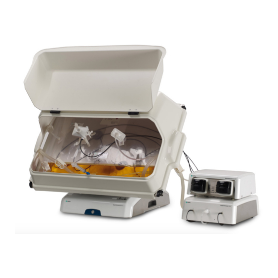
System overview Introduction ReadyToProcess WAVE 25 is intended for cell cultivation. A disposable Cellbag bioreactor is placed on a rocker and filled with gas, partially filled with culture medium, and inoculated with cells. Gas transfer and mixing of culture is accomplished by wave-induced agitation, performed by the rocker unit. - Page 13 Cellbag bioreactors independently. Both single and dual modes can support up to three ReadyToProcess Pump 25 units. Part Description Hatch Filter heater Cellbag bioreactor ReadyToProcess Pump 25 ReadyToProcess CBCU ReadyToProcess WAVE 25 rocker Tray ReadyToProcess WAVE 25 User Manual 29009598 AD...
- Page 14 The pressure control valve maintains a constant overpressure inside the Cellbag bioreactor. The rocking mechanism sets the rocking platform in motion. Wave motions are induced by the rocking. The culture is cautiously mixed, and gases are transferred into the culture. ReadyToProcess WAVE 25 User Manual 29009598 AD...
- Page 15 15% and measured between 0% and 20%. concentration in gas mix can be measured between 0% and 50%, and controlled between 0% and 50% with N and between 21% and 50% with air. ReadyToProcess WAVE 25 User Manual 29009598 AD...
-
Page 16: Readytoprocess Wave 25 Rocker
Front view of the rocker The illustration below shows the front view of the rocker. ReadyToProcess WAVE 25 User Manual 29009598 AD... - Page 17 The adjustable foot is placed in the front right corner of the rocker base when viewed from the front. It is used to distribute weight evenly over the four rocker feet. Use the supplied adjustable foot wrench to adjust the foot. ReadyToProcess WAVE 25 User Manual 29009598 AD...
- Page 18 The rocker is fitted with internal electrical fuses that are not user-replace- able. Tray and lid sizes Trays and lids are available in the different sizes listed below: Trays Lids Tray 10 Lid 10 Tray 20 Lid 20 Tray 50 Lid 50 ReadyToProcess WAVE 25 User Manual 29009598 AD...
- Page 19 Bag clamp (upper) Bag clamp opener (one in each upper corner) Bag clamp opener (one in each lower corner) Bag clamp (lower) The illustration below shows the rocker with Tray 50 and Lid 50 mounted. ReadyToProcess WAVE 25 User Manual 29009598 AD...
- Page 20 2 System description 2.2 ReadyToProcess WAVE 25 rocker Part Description Rocker base Tray Tubing exit Hatch ReadyToProcess WAVE 25 User Manual 29009598 AD...
- Page 21 Take care when tilting the rocker tray with full Cellbag bioreactor(s) attached. Step Action Prepare for tilt as described above or select the largest possible angle in UNICORN. Do not tilt the tray from an angle lower than 12°. ReadyToProcess WAVE 25 User Manual 29009598 AD...
- Page 22 2 System description 2.2 ReadyToProcess WAVE 25 rocker Step Action Hold the textured grip area on each side of the tray and pull the tray towards you. The illustration below shows the tilt position: ReadyToProcess WAVE 25 User Manual 29009598 AD...
- Page 23 2.2 ReadyToProcess WAVE 25 rocker Filter heater The filter heater prevents condensation and clogging of the outlet vent filter on the Cellbag bioreactor. Part Description Filter heater Connector for connection to the rocker Filter heater stand ReadyToProcess WAVE 25 User Manual 29009598 AD...
-
Page 24: Readytoprocess Cbcu
Gas outlet for connection to Cellbag bioreactor. Status LED Indicates the CBCU operating status. DO port Connector for DO sensor fiber cable. Status LED The status LED indicates the CBCU operating status according to the following table. ReadyToProcess WAVE 25 User Manual 29009598 AD... - Page 25 Inlet connection for CO supply. AIR/N2 Inlet connection for air or N supply. CAN ID The CAN ID is a unit number used by UNICORN to recognize the CBCU that is connected to the system. ReadyToProcess WAVE 25 User Manual 29009598 AD...
- Page 26 147.6" (375 cm) Silicone 3/16" (4.8 mm) 3/8" (9.5 mm) 7.9" (20 cm) Connectors Item Inner diameter Reducer connector, gas tubing 1/8" to 3/16" (3.2 to 4.8 mm) Connector, CBCU 1/8" (3.2 mm) ReadyToProcess WAVE 25 User Manual 29009598 AD...
-
Page 27: Readytoprocess Pump 25
Green flashing light Pumping is ongoing. Red flashing light Indicates an internal error, but the pump is still operating. Steady red light Indicates an internal error, and the pump is not operating properly. ReadyToProcess WAVE 25 User Manual 29009598 AD... - Page 28 1 for the first pump, position 2 for the second pump and so on. Tip: The pumps are identified in UNICORN by their CAN ID. Label each pump unit with its CAN ID to simplify identification of the physical pump. ReadyToProcess WAVE 25 User Manual 29009598 AD...
-
Page 29: Cellbag Bioreactor
Cellbag bioreactors with internal cell retention filters are available for perfusion culture. If required, it is possible to customize the Cellbag bioreactors. The following bag sizes are available for ReadyToProcess WAVE 25: • 2 L • 10 L •... - Page 30 (DO). The sensors are light sensitive and should be protected from excessive light. The sensors are located in the center of a sensor port on the Cellbag bioreactor and must be coupled to a sensor adapter, see table below. ReadyToProcess WAVE 25 User Manual 29009598 AD...
- Page 31 The optical lens of the fiber cable is located in the center of the sensor adapter. The fiber cable is connected to a sensor reader in the CBCU. The fiber cable is connected to the pH or DO port on the CBCU front panel. ReadyToProcess WAVE 25 User Manual 29009598 AD...
-
Page 32: Unicorn Software Overview
The UNICORN software, on page 36 Note: Software illustrations in these instructions are examples, and may differ from your software in some details. In this section Section See page 2.6.1 General UNICORN operation 2.6.2 UNICORN help ReadyToProcess WAVE 25 User Manual 29009598 AD... -
Page 33: General Unicorn Operation
• click the Taskbar button of the module of interest, • choose the module of interest in the Tools menu in any of the other software modules. The illustration below shows the Tools menu of the Evaluation module. ReadyToProcess WAVE 25 User Manual 29009598 AD... -
Page 34: Unicorn Help
• select Help →Help for... in any of the UNICORN term in the online help modules (see illustration above) • in the Search pane, enter the term of interest in the input field • click the Search button ReadyToProcess WAVE 25 User Manual 29009598 AD... - Page 35 In the System Control module: • select Manual →Execute Manual Instructions • expand a heading and select the instruction of interest • press the F1 key click the Help icon in the dialog ReadyToProcess WAVE 25 User Manual 29009598 AD...
-
Page 36: The Unicorn Software
Detailed information about the UNICORN software is available in the UNICORN user documentation and in the UNICORN Online Help . In this chapter Section See page Administration System control Methods in UNICORN Evaluation in UNICORN ReadyToProcess WAVE 25 User Manual 29009598 AD... -
Page 37: Administration
UNICORN and System Log provides the system administrator with records of usage and activity. System Properties is used to define the system and edit system proper- ties. Database Management is used for maintenance of the database. ReadyToProcess WAVE 25 User Manual 29009598 AD... -
Page 38: System Control
Tip: To get more information than is shown in the Process Picture, select View → Run Data to open the Run Data pane which presents current data in numerical values. ReadyToProcess WAVE 25 User Manual 29009598 AD... - Page 39 Icons for the left-hand bioreactor are in the upper half of the process picture and icons for the right-hand bioreactor in the lower half. ReadyToProcess WAVE 25 User Manual 29009598 AD...
- Page 40 In dual mode, place the pumps connected to the left and right Cellbag bioreactors on the left and right sides of the rocker respectively. ReadyToProcess WAVE 25 User Manual 29009598 AD...
- Page 41 Click on the left-hand side of the button. function The example below shows the settings for dissolved oxygen, DO. Enter appropriate values in the Settings dialog and click Adjust the settings OK or press enter. ReadyToProcess WAVE 25 User Manual 29009598 AD...
- Page 42 Follow the instructions below to customize which curves to show in the chart. Refer to the online help for further information about the tabs in the Customize dialog. ReadyToProcess WAVE 25 User Manual 29009598 AD...
- Page 43 The System Settings dialog in System Control is used to view and edit the system setting for the currently selected instrument before the run is started. Follow the instructions below to change the System Settings. Available settings are described in Section 8.5 Control settings, on page 251. ReadyToProcess WAVE 25 User Manual 29009598 AD...
- Page 44 It is possible to interact manually with an ongoing run using Manual instructions. Follow the instructions below to perform manual instructions. Note: It is also possible to interact with the system manually directly from the Process Picture. ReadyToProcess WAVE 25 User Manual 29009598 AD...
- Page 45 To change the Run Data display, select View →Run Data, right click in the Run Data pane and: • select Run Data Groups →Detailed to show more details • select Customize to customize the appearance of the Run Data pane. ReadyToProcess WAVE 25 User Manual 29009598 AD...
-
Page 46: Methods In Unicorn
In this section Section See page 3.3.1 Method editor 3.3.2 Method creation 3.3.3 Work with methods 3.3.4 Text instructions 3.3.5 Save a method 3.3.6 Scouting 3.3.7 Method queues ReadyToProcess WAVE 25 User Manual 29009598 AD... -
Page 47: Method Editor
(3), containing the two tabs Phase Properties and Text Instructions. Method Editor toolbar icons The table below shows the Method Editor toolbar icons that are referred to in this User Manual. ReadyToProcess WAVE 25 User Manual 29009598 AD... - Page 48 Method notes: Opens the Method Notes dialog, where notes can be added to the method. Scouting: Opens the Scouting Variables dialog, which is used to repeat a series of method runs. New method queue: Opens the Method Queue dialog. ReadyToProcess WAVE 25 User Manual 29009598 AD...
-
Page 49: Method Creation
3 The UNICORN software 3.3 Methods in UNICORN 3.3.2 Method creation 3.3.2 Method creation Predefined method Follow the instructions below to create a new method using a predefined method as template: ReadyToProcess WAVE 25 User Manual 29009598 AD... - Page 50 3.3 Methods in UNICORN 3.3.2 Method creation Step Action In the Method Editor: • click the Create a new method icon in the Toolbar • selectFile →New Method... Result: The New Method dialog opens. ReadyToProcess WAVE 25 User Manual 29009598 AD...
- Page 51 Follow the instructions below to create a new empty method: Step Action In the Method Editor: • click the Create a new method icon in the Toolbar • selectFile →New Method... Result: The New Method dialog opens. ReadyToProcess WAVE 25 User Manual 29009598 AD...
- Page 52 In the New Method dialog: a. select a System b. select the Empty Method radio button c. click OK Result: An empty method that consists of the mandatory Method Settings phase is created. ReadyToProcess WAVE 25 User Manual 29009598 AD...
-
Page 53: Work With Methods
Step Action In the Method Editor: • Click the Open Method Navigator icon in the Toolbar • select File →Open... • select View →Method Navigator Result: The Method Navigator is displayed. ReadyToProcess WAVE 25 User Manual 29009598 AD... - Page 54 Select the User Defined phase in the Phase Library pane and drag-and- drop the phase to the requested position in the Method Outline pane. Result: The phase is included in the method at the requested position. ReadyToProcess WAVE 25 User Manual 29009598 AD...
- Page 55 User Defined phase, select the Text Instructions tab. The Phase Properties tab will only show the variables used in this phase. See Section 3.3.4 Text instructions, on page 59 for information about how to work with instructions in the Text Instructions pane. ReadyToProcess WAVE 25 User Manual 29009598 AD...
- Page 56 Result:The phase is moved one step up or down in the Method Outline. Set up a Start Protocol Follow the instructions below to set up a Start Protocol to be displayed before the method run starts. ReadyToProcess WAVE 25 User Manual 29009598 AD...
- Page 57 Result Name and Location is selected by default. b. Click OK to confirm and close the dialog. Add/edit Method Notes Follow the instructions below to add notes to a method or edit existing notes. ReadyToProcess WAVE 25 User Manual 29009598 AD...
- Page 58 Enter/edit notes about the method. If notes already have been entered, it is possible to search for specific words using the Find... button. b. Click OK to confirm and close the dialog. ReadyToProcess WAVE 25 User Manual 29009598 AD...
-
Page 59: Text Instructions
Follow the steps below to insert a new text instruction in the Text Instructions area: Step Action Select a block and display the instructions within the block. Select the instruction in the block after which you want to add the new instruction. ReadyToProcess WAVE 25 User Manual 29009598 AD... - Page 60 For example, if the breakpoint for the current instruction is lower than that for the new instruction it is inserted as the first instruction at that breakpoint. ReadyToProcess WAVE 25 User Manual 29009598 AD...
- Page 61 The parameters for the instruction are shown in the Instruction Box. a. Locate the breakpoint or the required parameter in the Instruction box. b. Click the Var... button. Result: The New Variable dialog opens. ReadyToProcess WAVE 25 User Manual 29009598 AD...
- Page 62 When the instruction is shown in the Instructions field of the Instruction Box, the text on the button to the left of the parameter field is displayed as VAR..The button text for parameters not having associated variables is Var..ReadyToProcess WAVE 25 User Manual 29009598 AD...
- Page 63 Edit Variable..Result: The Edit Variable dialog opens displaying all variables (if opened from the Text Instructions pane) or the phase variables (if opened from the Phase Properties tab). ReadyToProcess WAVE 25 User Manual 29009598 AD...
- Page 64 Confirm that you want to delete the variable in the dialog that appears. Click Close to close the dialog. Edit a variable using the VAR.. button in the Instruction Box Follow the instructions below to edit a variable using the Instruction Box: ReadyToProcess WAVE 25 User Manual 29009598 AD...
- Page 65 Select the instruction containing the variable to be edited in the Text Instructions area. Result: The parameters for the instruction are shown in the Instruction Box. Click the VAR... button for the appropriate variable. Result: The Edit Variable dialog opens. ReadyToProcess WAVE 25 User Manual 29009598 AD...
- Page 66 Uncheck the box to set it to a normal variable. c. Click Clear to delete the variable. Click OK. To save the changes, click Change in the Instruction Box. Result: The text instruction is updated. ReadyToProcess WAVE 25 User Manual 29009598 AD...
-
Page 67: Save A Method
• If the method has been named and saved previously, the changes are saved immediately. • Otherwise, the Save As dialog opens. Proceed with steps 2-4 below. Browse for an appropriate folder, or create a new one. ReadyToProcess WAVE 25 User Manual 29009598 AD... - Page 68 Note: A Method Settings phase cannot be saved as a separate phase with a new name. If properties for the Method Settings phase are changed, the changes will be saved with the method. ReadyToProcess WAVE 25 User Manual 29009598 AD...
- Page 69 The Save Phase to Phase Library dialog opens. • Type a Phase name • Choose a phase from the Phase name drop-down list. This phase will be replaced by the phase with the new settings. ReadyToProcess WAVE 25 User Manual 29009598 AD...
- Page 70 Select if the phase shall be Global (available for all users) or Personal (for your own use only). b. Click OK. Result: The phase is saved and is available in the Global Phases or Personal Phases panel of the Phase Library. ReadyToProcess WAVE 25 User Manual 29009598 AD...
-
Page 71: Scouting
Section 3.3.2 Method creation, on page 49 for information about how to create methods. See subsection Edit variables in Section 3.3.4 Text instructions, on page 59 for information about how to define new variables. ReadyToProcess WAVE 25 User Manual 29009598 AD... - Page 72 • Click the Scouting icon in the toolbar • SelectTools →Scouting Result: The Scouting dialog opens with the Scouting Variables dialog displayed on top. Note: When editing a scouting scheme, only the Scouting dialog is displayed. ReadyToProcess WAVE 25 User Manual 29009598 AD...
- Page 73 The Scouting dialog is updated with the selected variables and their default values. It is possible to insert runs one by one (see step 4) or insert series of runs (see step 5). ReadyToProcess WAVE 25 User Manual 29009598 AD...
- Page 74 Repeat until all runs are included using the correct variable values. Note: The scouting scheme can also be edited just prior to starting the method run in the Start Protocol. Here variable values can be changed and indi- vidual runs included or excluded. ReadyToProcess WAVE 25 User Manual 29009598 AD...
- Page 75 The Insert Series dialog for the selected variable opens. In the Insert Series dialog: a. Enter Start value:, Step by: and Number of runs:. In this example, 20, 2 and 5. b. Click OK. Result: The Scouting parameters table is updated. ReadyToProcess WAVE 25 User Manual 29009598 AD...
- Page 76 Enter the appropriate range, for example: 20-23,25-28 c. Click OK. Result: The Scouting parameters table is updated. Click OK in the Scouting dialog to save the scouting scheme. Save the method. ReadyToProcess WAVE 25 User Manual 29009598 AD...
-
Page 77: Method Queues
Follow the instructions below to create a method queue. Step Action In the Method Editor: • click the New Method Queue icon in the Toolbar • Select File →New Method Queue... Result: The Method Queue dialog opens. ReadyToProcess WAVE 25 User Manual 29009598 AD... - Page 78 Choose a system for each method queue block from the System drop down list. Choose a Method to add to a method queue by pressing the browse button. Result: The Select Method dialog opens. ReadyToProcess WAVE 25 User Manual 29009598 AD...
- Page 79 In the Select Method dialog, browse to the required method and click OK. Result: The method is added to the method queue. Note: For reasons of system compatibility, the individual methods should be saved for the system on which they are queued. ReadyToProcess WAVE 25 User Manual 29009598 AD...
- Page 80 The first Method for the first System will always have its Start Condition set to At queue start. Available Start Conditions are: Repeat steps 4 to 6 to add further methods to the Method list for each required system. ReadyToProcess WAVE 25 User Manual 29009598 AD...
- Page 81 Click Save or Save As to save the completed method queue. Note: An error dialog will be displayed if any of the methods are incompatible with the system on which they are queued. ReadyToProcess WAVE 25 User Manual 29009598 AD...
-
Page 82: Evaluation In Unicorn
Section See page 3.4.1 Evaluation 3.4.2 Open and view results 3.4.3 Run documentation 3.4.4 Generate and print a predefined report format 3.4.5 Create a new report format 3.4.6 Edit an existing report format ReadyToProcess WAVE 25 User Manual 29009598 AD... -
Page 83: Evaluation
Evaluation toolbar icons The table below shows the Evaluation toolbar icons that are referred to in this User Manual. Icon Function Open Result Navigator: Opens the Result Navigator where available results are listed. ReadyToProcess WAVE 25 User Manual 29009598 AD... - Page 84 View Documentation: Opens the Documentation dialog that contains the complete documentation for a manual or a method run. Customize: Opens the Customize dialog where for example curve settings can be set. ReadyToProcess WAVE 25 User Manual 29009598 AD...
-
Page 85: Open And View Results
If the result is already open at another network workstation, you can only open it in read-only mode. A message similar to the illustration below will open. ReadyToProcess WAVE 25 User Manual 29009598 AD... - Page 86 You can use the vertical marker for more measurements than just the readings from a specific curve position. Follow the instructions below to use the marker to determine Delta and Mean Y-axis values. ReadyToProcess WAVE 25 User Manual 29009598 AD...
- Page 87 The measured area is colored as illustrated below: a. Read the Delta and Mean values from the box: Snapshots Follow the instructions below to take a Snapshot of all the curve values at the marker position. ReadyToProcess WAVE 25 User Manual 29009598 AD...
- Page 88 Documentation dialog. Click the Close button to close the Snapshot dialog. Note: The snaphot will record only the values of curves that are displayed. Curves that are filtered will not be recorded. ReadyToProcess WAVE 25 User Manual 29009598 AD...
-
Page 89: Run Documentation
• Choose View →Documentation • Click the view Documentation icon. Result: The Documentation dialog opens. See further information about the tabs and contents below. a. Click the Print button. Result: The Print dialog opens. ReadyToProcess WAVE 25 User Manual 29009598 AD... - Page 90 Some of the items listed below may be excluded from the Run Documen- tation. Tabs will be shown only for items that have been included in the method. Documentation tab Contents Result Information The Result Information tab contains general informa- tion about the result. ReadyToProcess WAVE 25 User Manual 29009598 AD...
- Page 91 The list can show detail and/or unused variables. At this stage, the variable values are no longer possible to edit. Scouting The Scouting tab shows the scouting parameter settings. This tab corresponds to the Scouting settings in the Method Editor. ReadyToProcess WAVE 25 User Manual 29009598 AD...
- Page 92 The table below describes how to find specific text in the logs. Step Action Select the log tab where you want to perform your search. a. Click the Find button. Result: The Find dialog opens. ReadyToProcess WAVE 25 User Manual 29009598 AD...
- Page 93 The Save As dialog box opens. a. Select the appropriate destination folder. b. Type a name in the Name text box. c. Select a system from the System droplist. a. Click OK. Result: The method is saved. ReadyToProcess WAVE 25 User Manual 29009598 AD...
-
Page 94: Generate And Print A Predefined Report Format
• Click the Report icon. Result: The Generate Report dialog opens. a. Select a Format for the report. Note: Global report formats are noted by the text Global before the report format name in this list. ReadyToProcess WAVE 25 User Manual 29009598 AD... - Page 95 The Save As dialog opens. a. Browse for a folder and File name for the report. b. Click Save. Result: The report is created as a PDF file and saved in the location specified in the dialog. ReadyToProcess WAVE 25 User Manual 29009598 AD...
-
Page 96: Create A New Report Format
Open a result in the Evaluation module. • Select File →Report. • Click the Report icon. Result: The Generate Report dialog box opens. a. Click the New button. Result: The Customize Report window opens in Edit mode. ReadyToProcess WAVE 25 User Manual 29009598 AD... - Page 97 This button displays the next page or pair of pages (if there is more than one page). One Page/Two Pages This button toggles between single page view and pairs of pages view (if there is more than one page). ReadyToProcess WAVE 25 User Manual 29009598 AD...
- Page 98 Saves the edited report format. Note: → Save menu command. You can also choose the File Cuts the selected object from the report. Note: → Cut menu command. You can also choose the Edit ReadyToProcess WAVE 25 User Manual 29009598 AD...
- Page 99 • Double-click anywhere on the report page (not on an object) • Right-click (not on an object) and choose Properties from the shortcut menu • Choose the Edit →Page setup menu command. Result: The Page Setup dialog box opens. ReadyToProcess WAVE 25 User Manual 29009598 AD...
- Page 100 Click OK to apply the changes. Report items toolbar icons The table below describes the different functions of the report items toolbar icons in the Customize Report window: Icon Function Adds free text. Adds a picture. ReadyToProcess WAVE 25 User Manual 29009598 AD...
- Page 101 • If you want to edit an object later, double-click the object box. • The size of the object in Edit mode does not always correspond to the size in the printed report. Click Preview in the toolbar for a print preview. ReadyToProcess WAVE 25 User Manual 29009598 AD...
- Page 102 Align right Matches the right alignment of all selected objects to that of the high- lighted object. Align top Matches the top alignment of all selected objects to that of the high- lighted object. ReadyToProcess WAVE 25 User Manual 29009598 AD...
- Page 103 The Make same size and Make same width functions can only be used to resize the width of charts, free text and picture objects. Save the report format Follow the instructions below to save the finished report format: ReadyToProcess WAVE 25 User Manual 29009598 AD...
- Page 104 Select if you want to save the format for global use. c. Select if you want to save the format as default. Note: The name for the default format will automatically be changed to DEFAULT. a. Click OK to save the format. ReadyToProcess WAVE 25 User Manual 29009598 AD...
-
Page 105: Edit An Existing Report Format
Once you have made a change, the title bar of the window will add the word Modified to the report format name. • Select File →Save • Click the Save icon. Result: The edited format is saved. ReadyToProcess WAVE 25 User Manual 29009598 AD... - Page 106 → Save As in about how to add or edit report items. You can also select File the Customize Report window, to save the edited format under another name and keep the original report format unchanged. ReadyToProcess WAVE 25 User Manual 29009598 AD...
-
Page 107: System Control Description
In this chapter Section See page Single and dual operation modes Temperature measurement and control pH and DO measurement and control pH control DO control Media control Recommended operating conditions System verification ReadyToProcess WAVE 25 User Manual 29009598 AD... -
Page 108: Single And Dual Operation Modes
Single and dual operation modes Introduction ReadyToProcess WAVE 25 supports cell cultivation in single and dual modes: • In single mode, the system supports culture in one Cellbag bioreactor at one time. The rocker is connected to one ReadyToProcess CBCU and up to three ReadyToProcess Pump 25 units. -
Page 109: Temperature Measurement And Control
21°C. The difference is reduced by 1°C for every °C increase in the ambient temperature (for example, a differ- ence of 6°C can be maintained at ambient temperature 25°C). ReadyToProcess WAVE 25 User Manual 29009598 AD... -
Page 110: Ph And Do Measurement And Control
This section describes the pH and DO measurement and control principles of the ReadyToProcess WAVE 25 system. In this section Section See page 4.3.1 pH and DO measurement principles 4.3.2 pH and DO control principles ReadyToProcess WAVE 25 User Manual 29009598 AD... -
Page 111: Ph And Do Measurement Principles
950 mbar, it will not show 100% air if the same content is later equilibrated at another atmospheric pressure, say 1050 mbar. The difference is approximately 1% air saturation/10 mbar. ReadyToProcess WAVE 25 User Manual 29009598 AD... - Page 112 2000 m corresponds to (800/1013) × 21 = 16.6 vol% of that at sea level. Different growth conditions will therefore be obtained at high altitudes as compared to sea level. ReadyToProcess WAVE 25 User Manual 29009598 AD...
-
Page 113: Ph And Do Control Principles
The pH and DO control software automatically calculates the following parameters suitable for the actual control case, taking into account the bag size and gas flow setpoint: • Cycle time • PID parameters ReadyToProcess WAVE 25 User Manual 29009598 AD... - Page 114 • An orange frame indicates that the inactivation is due to a user or system action, like entering sampling mode or feed/harvest auto calibration. • A red frame indicates that the inactivation is due to an error. ReadyToProcess WAVE 25 User Manual 29009598 AD...
-
Page 115: Ph Control
About this section ReadyToProcess WAVE 25 has automated pH control. In general, PID parameters and cycle times do not need to be entered or tuned, acid and base flow rates do not need to be calibrated or tuned. Refer to Section 8.5.7 pH measurement, on page 263... -
Page 116: Ph Control Schemes
The traditional deadband mode of pH control involves controlling the pH to reach the limit of the pH deadband set by the user. The traditional deadband mode of pH control can be used in all three control schemes. ReadyToProcess WAVE 25 User Manual 29009598 AD... - Page 117 Click on alternative pH control deadband mode. Click one of the radio buttons Optimal or Traditional to select mode. Note: The selected mode of deadband cannot be changed during a run. Click OK to confirm the selection. ReadyToProcess WAVE 25 User Manual 29009598 AD...
-
Page 118: Co2 Control Mode
The automatic PID parameters are shown as Run Data. Register the values both when approaching the new setpoint, and when keeping the setpoint. Tip: The automatically computed values are a good starting point for the tuning. ReadyToProcess WAVE 25 User Manual 29009598 AD... - Page 119 (advanced CO2) and select Manual PID parameter mode and/or Cycle time mode and enter the applicable values. When elaborating with a manual I parameter, remember that increasing the I parameter will reduce the integrating effect and vice versa. Click Execute. ReadyToProcess WAVE 25 User Manual 29009598 AD...
-
Page 120: Acid/Base Control Mode
Click Execute. Flow rate ReadyToProcess WAVE 25 automatically computes flow rates for acid and base. There is no need for calibration or tuning of acid/base flow rates. To make this automation work, the following input data needs to be correct:... - Page 121 A deadband is defined for acid and base individually. When the control output is in the deadband, the pumps will not run. pH deadband prevents the pH control from switching between small acid and base additions. Optimal mode of pH control -75% ReadyToProcess WAVE 25 User Manual 29009598 AD...
- Page 122 The default value of 2.0% is found to be a good compro- mise. The deadband can be changed in System →Manual Instructions →pH control (optimal acid/base). ReadyToProcess WAVE 25 User Manual 29009598 AD...
- Page 123 0.1% to 2 pH units on each sitde of the setpoint. While residing in traditional deadband, in the CO2 and the CO2/Base scheme of control, the minimum CO2 % that is set by the user is maintained. ReadyToProcess WAVE 25 User Manual 29009598 AD...
- Page 124 The help text for the traditional deadband mode provides valuable information. Click the symbol with the question mark in the blue square in the left corner of the screen to launch the help text. ReadyToProcess WAVE 25 User Manual 29009598 AD...
-
Page 125: Ph Control Transition Delays
UNICORN IC 2.0.8.0 will apply for various cellbag sizes and gas flow rates to allow the process to naturally drift to the new setpoint. ReadyToProcess WAVE 25 User Manual 29009598 AD... -
Page 126: Do Control
4 System control description 4.5 DO control DO control About this section ReadyToProcess WAVE 25 has automated DO control using O . In general, PID param- eters and cycle times do not need to be entered or tuned. Refer to Section 8.5.9 DO measurement, on page 272 Section 8.5.10 DO control, on page 274... -
Page 127: Do Control Schemes
• DO control by change of O concen- tration in the gas mix, and by Speed changing the rocking speed. • Control starts in O2 mode and then switches automatically between 02 and Speed mode as required. ReadyToProcess WAVE 25 User Manual 29009598 AD... -
Page 128: O2 Control Mode
The automatic PID parameters are shown as Run Data. Register the values both when approaching the new setpoint, and when keeping the setpoint. Tip: These automatic values are a good starting point for the tuning. ReadyToProcess WAVE 25 User Manual 29009598 AD... - Page 129 (advanced O2) and select Manual PID parameter mode and/or Cycle time mode and enter the desired values. When adjusting a Manual I parameter, remember that increasing the I parameter will reduce the integrating effect and vice versa. Click Execute. ReadyToProcess WAVE 25 User Manual 29009598 AD...
-
Page 130: Speed Control Mode
Cycle time The cycle time parameter sets the cycle time of the DO speed control. This cycle time will override the DO reading cycle time when the DO control is on. ReadyToProcess WAVE 25 User Manual 29009598 AD... -
Page 131: O2/Speed Control Scheme
UNICORN IC 2.0.8.0 will apply for various cellbag sizes and gas flow rates to allow the process to naturally drift to the new setpoint. ReadyToProcess WAVE 25 User Manual 29009598 AD... -
Page 132: Media Control
Media control can be used in dual mode, but the accuracy will be lower than in single mode (see Section 4.6.1 Weight measurement, on page 133). In this section Section See page 4.6.1 Weight measurement 4.6.2 Media addition 4.6.3 Perfusion 4.6.4 Deviation alarm 4.6.5 Media control inactivation ReadyToProcess WAVE 25 User Manual 29009598 AD... -
Page 133: Weight Measurement
3% of the load to the weighing error. Since the bioreactor may move during rocking, it is important to make sure that the bench (and therefore the rocker) is stable and horizontal. ReadyToProcess WAVE 25 User Manual 29009598 AD... -
Page 134: Media Addition
Calibrating the pump before running media addition can give more accurate measure- ment of the accumulated feed volume. ReadyToProcess WAVE 25 User Manual 29009598 AD... -
Page 135: Perfusion
It is however recommended to also calibrate the harvest pump, since unnecessary warnings for harvest filter clogging may otherwise be issued. The accumulated volume will also be more precisely computed if the pumps are calibrated. ReadyToProcess WAVE 25 User Manual 29009598 AD... - Page 136 L/day should be read as kg/day instead. If perfusion is running at the weight setpoint with both pumps operating and the auto calibration disabled, enabling auto calibration will trigger an immediate auto calibra- tion. ReadyToProcess WAVE 25 User Manual 29009598 AD...
- Page 137 30 minutes. If auto calibration is enabled, and the criteria above cannot be fulfilled, the media control cannot start unless the flow rate is increased or the auto calibration is disabled. ReadyToProcess WAVE 25 User Manual 29009598 AD...
- Page 138 10% from the weight setpoint. The stopped pump will start again when the setpoint is reached. ReadyToProcess WAVE 25 User Manual 29009598 AD...
-
Page 139: Deviation Alarm
The deviation alarm can be deactivated using the manual instruction Media control (general). During media addition, the deviation alarm is acting on the momentary weight setpoint. During perfusion, the deviation alarm is active only in normal perfusion when both pumps are running. ReadyToProcess WAVE 25 User Manual 29009598 AD... -
Page 140: Media Control Inactivation
A message dialog will show why the control is inac- tive. • An orange frame indicates that the inactivation is due to sampling mode. • A red frame indicates that the inactivation is due to an error. ReadyToProcess WAVE 25 User Manual 29009598 AD... -
Page 141: Recommended Operating Conditions
10 rpm and 4 degrees, if sufficient oxygen transfer and mixing is maintained. Each new cell line and process requires optimization of operating conditions. The table below shows typical rocking speed and gas flow settings for suspension cell culture. ReadyToProcess WAVE 25 User Manual 29009598 AD... - Page 142 • A too low gas flow can lead to insufficient inflation of the Cellbag bioreactor. Refer to Gas flow table for recommendations on suitable gas flow rates. Recommendations to reduce foaming To reduce foaming, the following should be taken into consideration: ReadyToProcess WAVE 25 User Manual 29009598 AD...
- Page 143 • Excessive foaming occurs if the Cellbag bioreactor is not rigidly inflated. Check that the gas flow is sufficient and that the pressure relief valve is functioning. ReadyToProcess WAVE 25 User Manual 29009598 AD...
-
Page 144: System Verification
→Rocking →Angle in the Process Picture. Click OK. Result: The rocking angle changes to the set value. b. Try some different setpoints of the rocking angle, and make sure that the rocking angle changes. ReadyToProcess WAVE 25 User Manual 29009598 AD... - Page 145 If the rocking speed, rocking angle or rocking motion appear not to function correctly, refer to Section 7.2 ReadyToProcess WAVE 25 rocker, on page 217. Stop the rocking by clicking the right-hand side of the Rocking button.
- Page 146 If the temperature control appears not to function correctly, refer to Section 7.2 ReadyToProcess WAVE 25 rocker, on page 217. Stop the heating by clicking the right-hand side of the Temp button. Stop the rocking by clicking the right-hand side of the Rocking button.
- Page 147 If the gas flow appears not to function correctly, refer to Section 7.3 Ready- ToProcess CBCU, on page 221. Verification of fast fill function Follow these instructions to make sure that the Fast fill functions properly: ReadyToProcess WAVE 25 User Manual 29009598 AD...
- Page 148 The gas flow is maximized to 3 L/min for 20 minutes or until Fast fill is manually turned off. The cellbag is inflated. Stop the gas flow when the cellbag has been fully inflated, by clicking the right-hand side of the Gas flow button. ReadyToProcess WAVE 25 User Manual 29009598 AD...
-
Page 149: Operation
5 Operation Operation About this chapter This chapter describes how to operate ReadyToProcess WAVE 25. In this chapter Section See page Set up the system Start and configure the system Prepare for cultivation Perform cultivation ReadyToProcess WAVE 25 User Manual 29009598 AD... -
Page 150: Set Up The System
Attach and detach tray 5.1.3 Prepare pH and DO sensors 5.1.4 Attach the Cellbag bioreactor 5.1.5 Prepare the pump 5.1.6 Connect gas to the system 5.1.7 Connect the filter heater to the rocker ReadyToProcess WAVE 25 User Manual 29009598 AD... -
Page 151: Select The Tray And Cellbag Bioreactor
DO control. The temperature, pH, and DO sensors need to be submerged in liquid throughout the complete rocking cycle to function correctly. ReadyToProcess WAVE 25 User Manual 29009598 AD... -
Page 152: Attach And Detach Tray
Tilt position is recommended, as described in the instructions below. Step Action Tilt the rocker platform by pulling the upper edge towards you. Lift the tray into the same angle as the rocker platform. ReadyToProcess WAVE 25 User Manual 29009598 AD... - Page 153 Detach tray The tray can be detached from the rocker platform in tilt position and in normal posi- tion. Tilt position is recommended, as described in the instructions below. ReadyToProcess WAVE 25 User Manual 29009598 AD...
- Page 154 Pull the tray towards you. Note: If the tray is detached with the rocker in normal position, you will need to lift the tray by the upper edge before sliding it away from you. ReadyToProcess WAVE 25 User Manual 29009598 AD...
-
Page 155: Prepare Ph And Do Sensors
The optical sensor spots have different colors. The spot on the pH sensor bag port is white/yellow and the spot on the DO sensor port is pink/black. If both pH and DO sensors are used, a separate fiber cable is needed for each sensor. ReadyToProcess WAVE 25 User Manual 29009598 AD... - Page 156 Rotate the sensor adapter clockwise to fix the pins on the sensor port to the adapter. A distinct "click" will indicate that the adapter is securely fastened. Note: When rotating the sensor adapter, make sure not to exert any force on the fiber cable. ReadyToProcess WAVE 25 User Manual 29009598 AD...
- Page 157 Connect the pH sensor cable to the pH port on the CBCU front panel. Connect the DO sensor cable to the DO port on the CBCU front panel. ReadyToProcess WAVE 25 User Manual 29009598 AD...
-
Page 158: Attach The Cellbag Bioreactor
For a Cellbag bioreactor that covers the whole tray, open both bag clamps. In dual mode or with a bioreactor that covers only half the tray, only one clamp needs to be opened. Insert the upper Cellbag rod into the opened bag clamp. ReadyToProcess WAVE 25 User Manual 29009598 AD... - Page 159 Cellbag bioreactor on the tray. Mount the lid on top of the tray. NOTICE Keep the Cellbag bioreactor covered with the lid throughout the cultivation to protect the optical sensors from excessive light exposure. ReadyToProcess WAVE 25 User Manual 29009598 AD...
-
Page 160: Prepare The Pump
The wall thickness of the tubing should be 1.6 mm (1/16"). Note: Pump tubing is not supplied with the system. Suitable tubing must be purchased separately. ReadyToProcess WAVE 25 User Manual 29009598 AD... - Page 161 Make sure that the pump is not running. Open the flip top of the pump head completely. Place the pointed tool in the small depression in the tubing holder on one side of the pump head. ReadyToProcess WAVE 25 User Manual 29009598 AD...
- Page 162 Load tubing Follow the instructions below to load tubing in the pump head and connect tubing to the Cellbag bioreactor. Step Action Make sure that the pump is switched off. ReadyToProcess WAVE 25 User Manual 29009598 AD...
- Page 163 Check that the tubing holder is adjusted to the correct position for your size of tubing. See instructions above. Place the tubing between the rotor rollers and the track, pressed against the inner wall of the pump head. ReadyToProcess WAVE 25 User Manual 29009598 AD...
- Page 164 Lower the flip top until it clicks into its fully closed position. Connect inlet and outlet tubing to the Cellbag bioreactor, for example acid, base, feed and harvest. Note: The pumping direction is indicated by the arrow on the pump head. ReadyToProcess WAVE 25 User Manual 29009598 AD...
-
Page 165: Connect Gas To The System
Cellbag bioreactors to the correct CBCU. This is easier if the respective CBCU units are placed on the left and right sides of the rocker respectively. Set up aeration and gas supply Follow the instructions below to connect gas to the bioreactor system. ReadyToProcess WAVE 25 User Manual 29009598 AD... - Page 166 (indicated by an arrow in the illustration below). Do not attach the filter heater to the inlet vent filter. The image below shows the filter heater mounted on the stand on the Cellbag bioreactor. ReadyToProcess WAVE 25 User Manual 29009598 AD...
- Page 167 1.0 to 1.5 bar to CO2 IN on the If applicable, connect the CO CBCU rear panel. gas source at at 1.0 to 1.5 bar to O2 IN on the If applicable, connect the O CBCU rear panel. ReadyToProcess WAVE 25 User Manual 29009598 AD...
- Page 168 Make sure to keep the inlet pressures within the stated limits (1.0 to 1.5 bar). Excessive pressure may cause internal tubing to loosen. NOTICE An unsteady inlet pressure will affect the speed of the gas flow and also the gas mix. ReadyToProcess WAVE 25 User Manual 29009598 AD...
-
Page 169: Connect The Filter Heater To The Rocker
To use two filter heaters during single mode, Filter heater (R) must be enabled. Activate Filter Heater (R) in Single mode, if applicable. a. Select System settings. b. Click Rocker. c. Click Enable Filter heater (R). ReadyToProcess WAVE 25 User Manual 29009598 AD... -
Page 170: Start And Configure The System
UNICORN and configure the system in the software. In this section Section See page 5.2.1 Start the system and log on to UNICORN 5.2.2 Connect to the system 5.2.3 Configure system properties 5.2.4 Configure system settings 5.2.5 Start a run ReadyToProcess WAVE 25 User Manual 29009598 AD... -
Page 171: Start The System And Log On To Unicorn
If Use Windows Authentication is checked, you may log on using your Windows username and password. Press the Power switch to start the rocker. Result: The Power button flashes green during start-up, and then lights steadily when the rocker is operational. ReadyToProcess WAVE 25 User Manual 29009598 AD... -
Page 172: Connect To The System
Action When the indicator light on the rocker front panel shows a steady green light, click the Connect to Systems icon in the System Control module. Result: The Connect to Systems dialog opens. ReadyToProcess WAVE 25 User Manual 29009598 AD... - Page 173 The detailed appearance of the process picture will vary according to your system setup. Tip: If UNICORN is unable to connect to the selected system, see Section 7.6.2 UNICORN System Control, on page 239. ReadyToProcess WAVE 25 User Manual 29009598 AD...
-
Page 174: Configure System Properties
The Instrument Configuration is the system specific control software. It is provided on a DVD with the system, and is also available for download. Contact your Cytiva representative if you need help to download the Instrument Configura- tion. Follow the instructions below to edit the system properties. - Page 175 All available components are shown in the Component selection list. a. Click the check-boxes to select or de-select components. b. Make sure the components selected match the units connected to the system. Click OK to apply the changes. ReadyToProcess WAVE 25 User Manual 29009598 AD...
-
Page 176: Configure System Settings
Step Action Select System →Settings in the System Control module. Select Pump setup from the list and click the + symbol to view the available pump heads. ReadyToProcess WAVE 25 User Manual 29009598 AD... - Page 177 Follow the instructions below to select the mode of pH control in deadband. Step Action Select System →Settings in the System Control module. Select pH control from the list and click the + symbol to view the available alternatives. ReadyToProcess WAVE 25 User Manual 29009598 AD...
- Page 178 In the Upper dead band field, select the upper limit by clicking the small arrows to the right of the field. The limits are selected in the range of 0.10 to 2.00 pH units. ReadyToProcess WAVE 25 User Manual 29009598 AD...
- Page 179 In the Base dead band field, select the base range of optimal deadband in % cycle time by clicking the small arrows to the right of the field. The limits are selected in the range of 0.00% to 10.00%. ReadyToProcess WAVE 25 User Manual 29009598 AD...
- Page 180 CO2 to Speed and Speed to CO2 tabs. Click Execute to apply the selection. Select transition delays in DO Control Follow the instructions below to select the transition delays in DO/Speed mode before starting a run. ReadyToProcess WAVE 25 User Manual 29009598 AD...
- Page 181 The limits are selected in the range of 0 to 500 minutes. The transition delay times set in Auto mode of DO control (advanced) can be visualized under the O2 to Speed and Speed to O2 tabs. Click Execute to apply the selection. ReadyToProcess WAVE 25 User Manual 29009598 AD...
-
Page 182: Start A Run
Pressing the Power button on the rocker while the rocker is switched on will shut down the system and stop any ongoing run. Start a manual run Follow the instructions below to start a manual run. ReadyToProcess WAVE 25 User Manual 29009598 AD... - Page 183 If pH and/or DO control will be used, enter the appropriate calibration data (printed on the Cellbag label). c. Click OK. Result: The Start Protocol dialog for the manual run opens. ReadyToProcess WAVE 25 User Manual 29009598 AD...
- Page 184 • follow the instructions below to create a new method using a predefined method as template. Step Action In Method Editor do either of the following: • click the Create a new method icon in the Toolbar • select File:New Method Result: The New Method dialog opens. ReadyToProcess WAVE 25 User Manual 29009598 AD...
- Page 185 End is displayed in the Run Log. This also applies when ending a manual run. Tip: In System Settings, it is possible to set Prepare for Tilt at END. ReadyToProcess WAVE 25 User Manual 29009598 AD...
- Page 186 Error and Alarm state click the End icon. permanently end the run Note: When you end a method run prematurely, you will be prompted to save or discard the partial result. ReadyToProcess WAVE 25 User Manual 29009598 AD...
-
Page 187: Prepare For Cultivation
Chapter 2 System description, on page In this section Section See page 5.3.1 Inflate the Cellbag bioreactor 5.3.2 Adjust pump parameters 5.3.3 Final checks before cultivation 5.3.4 Add and equilibrate culture medium 5.3.5 Prepare the sensors ReadyToProcess WAVE 25 User Manual 29009598 AD... -
Page 188: Inflate The Cellbag Bioreactor
Enable Fast fill. This will maximize the gas flow during the first 20 minutes. Note: Fast fill is disabled in the illustration below. Turn on Gas flow from the Process Picture by pressing the right-hand side of the Gas flow button. Result: The Cellbag is inflated. ReadyToProcess WAVE 25 User Manual 29009598 AD... -
Page 189: Adjust Pump Parameters
Molarity parameter to the equivalent molarity of NaOH or HCl for optimal pH control. If you are preparing a perfusion cultivation, enable auto-calibration or cali- brate the feed and harvest pumps to reach optimal precision. ReadyToProcess WAVE 25 User Manual 29009598 AD... -
Page 190: Final Checks Before Cultivation
Formation of gas bubbles in the water will confirm the relief valve function. ReadyToProcess WAVE 25 User Manual 29009598 AD... -
Page 191: Add And Equilibrate Culture Medium
Figure 2.1, on page Make sure that the lid and all other equipment that will be used during the run is placed on the tray, and that no tubing weighs down the tray. Click Tare. ReadyToProcess WAVE 25 User Manual 29009598 AD... - Page 192 Equilibrate to operating conditions Follow the instructions below to equilibrate the medium to operating conditions. For recommendations on operating conditions, refer to Section 4.7 Recommended operating conditions, on page 141. ReadyToProcess WAVE 25 User Manual 29009598 AD...
- Page 193 If applicable, turn on CO button in the Process Picture. Set the required temperature setpoint. Click the right-hand side of the Temp button to start heating. Equilibrate the medium for at least 2 hours. ReadyToProcess WAVE 25 User Manual 29009598 AD...
-
Page 194: Prepare The Sensors
Enter reference DO field. Click Calibrate. Close the Calibration dialog. Select Settings →DO in the Process Picture. Enter the desired values for Control and Setpoint. Check the Deviation Alarm and set the alarm limits if desired. ReadyToProcess WAVE 25 User Manual 29009598 AD... - Page 195 Enter the actual pH value in the Enter reference pH field. Click Calibrate. Close the Calibration dialog. Select Settings →pH in the Process Picture. Enter the desired values for Control and Setpoint. Check the Deviation Alarm and set the alarm limits if desired. ReadyToProcess WAVE 25 User Manual 29009598 AD...
- Page 196 5 Operation 5.3 Prepare for cultivation 5.3.5 Prepare the sensors Step Action Click OK. ReadyToProcess WAVE 25 User Manual 29009598 AD...
-
Page 197: Perform Cultivation
This section describes the basics of performing a cultivation. During the cultivation, key parameters are monitored and the settings can be adjusted. In this section Section See page 5.4.1 Inoculate the culture 5.4.2 Monitor and control the run 5.4.3 End a run ReadyToProcess WAVE 25 User Manual 29009598 AD... -
Page 198: Inoculate The Culture
ReadyMate™ connector. Unclamp the inlet tubing and inoculum container tubing. Transfer the desired volume of inoculum into the bag using a pump or gravity flow. ReadyToProcess WAVE 25 User Manual 29009598 AD... -
Page 199: Monitor And Control The Run
An example of the Process Picture is shown in the illustra- tion below. Details vary according to the system configuration. The button colors indicate the current state of the respective function as shown in the table below. ReadyToProcess WAVE 25 User Manual 29009598 AD... - Page 200 A few examples of different Process Picture displays when the system is in traditional deadband mode are shown below. The following example shows the Process Picture display when the system is in acid/ base deadband mode. ReadyToProcess WAVE 25 User Manual 29009598 AD...
- Page 201 Follow the instruction below to take samples from the Cellbag bioreactor. Step Action Stop the rocking motion from the Process Picture. ReadyToProcess WAVE 25 User Manual 29009598 AD...
- Page 202 → Rocking → Sampling → Stop angle. The time remaining in sampling mode is displayed in a countdown timer. Note: For small culture volumes, it may be necessary to position the tray into tilt position during sampling. Remove the cap from the blue sampling connector. ReadyToProcess WAVE 25 User Manual 29009598 AD...
- Page 203 Attach a sterile disposable syringe with luer connector onto the sampling connector. Release the tubing clamp and withdraw a sample into the syringe. Remove the syringe and wipe the top of the sampling connector again with 70% ethanol and replace the cap. ReadyToProcess WAVE 25 User Manual 29009598 AD...
- Page 204 Stop the rocking by clicking the right-hand side of the Rocking button in the Process Picture. Clamp off the inlet and outlet vent filters. Select Manual →Execute Manual Instructions, and send the instruction Rocker →Prepare for tilt. ReadyToProcess WAVE 25 User Manual 29009598 AD...
- Page 205 • Cellbag bioreactors with internal perfusion filter or connected to external retention filters • Harvest and feed pump Section 4.6.3 Perfusion, on page 135 for information on perfusion mode. Contact a Cytiva application specialist for advice on setting up perfusion culture. ReadyToProcess WAVE 25 User Manual 29009598 AD...
-
Page 206: End A Run
Disconnect the tubing from the inlet vent filter on the Cellbag bioreactor. Disconnect any other tubing and cables still connected to the Cellbag bioreactor. Release and remove the empty Cellbag bioreactor from the tray by pressing down the bag clamp opener. ReadyToProcess WAVE 25 User Manual 29009598 AD... - Page 207 Press the Power button on the rocker front panel. The light flashes green while shutting down. Note: If the rocker fails to shut down, keep the Power button pressed in more than 4 seconds to force a shutdown. Clean the bioreactor system units. ReadyToProcess WAVE 25 User Manual 29009598 AD...
-
Page 208: Maintenance
The maintenance manager in UNICORN keeps track of the usage of different compo- nents and shows alerts when it is time for maintenance and service. For detailed infor- mation about the maintenance manager, refer to UNICORN Administration and Technical manual. ReadyToProcess WAVE 25 User Manual 29009598 AD... -
Page 209: Calibration
Tempera- Contact Cytiva service personnel for assistance if needed. Service ture personnel use special equipment to achieve more accurate cali- bration. - Page 210 Select the appropriate monitor in the Monitor to calibrate drop down menu. Follow the instructions in the right-hand field and enter the correct values in the Calibration procedure field, and click Calibrate for each value. Close the Calibration dialog. ReadyToProcess WAVE 25 User Manual 29009598 AD...
-
Page 211: Pump Calibration
Enter the desired calibration run time and click Start pump. Run the calibra- tion for sufficient time to collect a reliably measurable volume of liquid. When the pump stops, enter the collected volume and click Finish calibra- tion. ReadyToProcess WAVE 25 User Manual 29009598 AD... - Page 212 The calibration factor is the relation between the expected flow to rpm conversion for the selected tube diameter and the result of the calibration. For feed and harvest/waste pumps, this value can be observed in the curve data chart. ReadyToProcess WAVE 25 User Manual 29009598 AD...
- Page 213 The pumps will give a warning if the observed calibration volume is outside the range -30% to 10% of the expected value. The calibration will be rejected if the observed cali- bration volume is outside the range -60% to 30% of the expected value. ReadyToProcess WAVE 25 User Manual 29009598 AD...
-
Page 214: Cleaning
6.3 Cleaning Cleaning Cleaning procedure To prevent microbial or cross contamination, ReadyToProcess WAVE 25 should be cleaned after each cultivation. The system must be turned off and unplugged before cleaning. • Clean the exterior of the system units with a damp cloth and a suitable cleaning agent. -
Page 215: Troubleshooting
This chapter describes troubleshooting and corrective actions for ReadyToProcess WAVE 25. If the suggested actions in this guide do not solve the problem or if the problem is not covered by this guide, contact your Cytiva representative for advice. In this chapter Section... -
Page 216: Readytoprocess Wave 25 System
System Control. Make sure all connected pumps is not defined in available components are selected for the UNICORN. system. See Section 5.2.3 Configure system prop- erties, on page 174. ReadyToProcess WAVE 25 User Manual 29009598 AD... -
Page 217: Readytoprocess Wave 25 Rocker
Rocker is in an error • Check the current alarms. state. • Reset power to the unit. • If you still get motor alarms, contact Cytiva service personnel. Tray is in tilt position. • Make sure that the tray is in normal position. - Page 218 • Check that the weight shown in the Process Picture matches the actual weight of the culture medium. If not, tare the scale with the weight of the content in the Cellbag entered as Net Weight. ReadyToProcess WAVE 25 User Manual 29009598 AD...
- Page 219 • Check that the movement of the rocker is not obstructed. Scale needs calibra- Calibrate the scale. See Section 6.1 Calibration, tion. on page 209. If needed, contact Cytiva service personnel. ReadyToProcess WAVE 25 User Manual 29009598 AD...
- Page 220 Tare the scale before or after filling the Cellbag rectly performed. bioreactors. See Tare the scale, on page 191. Weight reading fluctu- Rocker support Check that the table is rigid, flat and horizontal. ates or drifts. unstable. ReadyToProcess WAVE 25 User Manual 29009598 AD...
-
Page 221: Readytoprocess Cbcu
• If problem persists, transfer the contents to another Cellbag bioreactor. Disconnect the N /Air and Gas mix out tubing External gas source is Blocked gas tubing. connected but the gas and locate the blockage. flow shows zero. ReadyToProcess WAVE 25 User Manual 29009598 AD... - Page 222 (between 1.0 and 1.5 bar). Connections for CO or air have been mixed up. Incorrect setpoint. Check the setpoint. Error symptom Possible cause Corrective action No O reading. sensor is broken. Contact Cytiva service personnel. ReadyToProcess WAVE 25 User Manual 29009598 AD...
- Page 223 Manual instructions, on page actual case. Use the manual instruction pH control →pH The CO range is too narrow. control (CO2) to set the desired CO range for pH control. ReadyToProcess WAVE 25 User Manual 29009598 AD...
- Page 224 See Manual instructions, on page To get an initial suggestion of the PID parame- ters, look at the automatically selected parame- ters by selecting them as run data under Tools →Customize. ReadyToProcess WAVE 25 User Manual 29009598 AD...
- Page 225 Auto calibration of None. If the pH control is using acid or base, it is feed and harvest inactive during auto calibration. pumps is active. ReadyToProcess WAVE 25 User Manual 29009598 AD...
- Page 226 Note: (appr. pH 5 to 9). It is a risk that the pH sensor has been damaged, especially if the pH has been above pH 10. ReadyToProcess WAVE 25 User Manual 29009598 AD...
- Page 227 DO control does not Some of the criteria for Read the message in the pop-up dialog. If start. starting the DO possible, take action according to the informa- control are not tion and try again. fulfilled. ReadyToProcess WAVE 25 User Manual 29009598 AD...
- Page 228 DO control using too slow or too fast speed step, max/min speed. (undershooting/over- speed and deadband shooting). are not optimal for the actual case. ReadyToProcess WAVE 25 User Manual 29009598 AD...
- Page 229 Process Picture into an inactive state. button is orange). New reading attempts are made with asked reading frequency until a valid reading is returned, or the reading is stopped. ReadyToProcess WAVE 25 User Manual 29009598 AD...
- Page 230 Note: If for example 5% CO is added to air flowing through the Cellbag the DO will be reduced with approximately the same percentage value. ReadyToProcess WAVE 25 User Manual 29009598 AD...
- Page 231 Auto calibration is None. This is normal. enabled, and the harvest pump is cali- brating. ReadyToProcess WAVE 25 User Manual 29009598 AD...
- Page 232 The media control is None of the pumps Start media control again. automatically turned started by the media off. control are no longer running. ReadyToProcess WAVE 25 User Manual 29009598 AD...
-
Page 233: Readytoprocess Pump 25
CAN indicator LED An internal error has Contact Cytiva service personnel. flashes. occurred, and the pump is not operating properly. Note: This is normal the first seconds during power ReadyToProcess WAVE 25 User Manual 29009598 AD... -
Page 234: Cellbag Bioreactor
Cellbag bioreactor. be underinflated. Inlet gas supply incor- Check that you have connected the inlet gas rectly connected. supply to the inlet filter (does not have the pres- sure control valve). ReadyToProcess WAVE 25 User Manual 29009598 AD... - Page 235 A small amount of condensate in the inlet filter is dialog indicates normal. However, if excessive condensate is blockage of gas flow. formed: • Decrease the gas flow. • Insulate the tubing to the pressure control valve. ReadyToProcess WAVE 25 User Manual 29009598 AD...
-
Page 236: Software Problems
This section describes troubleshooting and corrective actions for UNICORN 7.x. Refer to UNICORN Administration and Technical manual for more troubleshooting. In this section Section See page 7.6.1 Troubleshooting Method editor 7.6.2 UNICORN System Control 7.6.3 Troubleshooting Evaluation ReadyToProcess WAVE 25 User Manual 29009598 AD... -
Page 237: Troubleshooting Method Editor
Export of a method to a network drive fails Problem description Solution Export of a method to a network drive Ensure that the destination network drive is mapped and fails. that you have the appropriate access rights. ReadyToProcess WAVE 25 User Manual 29009598 AD... - Page 238 Problem description Solution A new instrument configuration is installed. After this, it The Method Editor must be restarted is still impossible to create a new method. after importing the new instrument configuration. ReadyToProcess WAVE 25 User Manual 29009598 AD...
-
Page 239: Unicorn System Control
Access to the Timer instruction must also be disa- A user without access to the function Method End may still end a method using a bled if users are not allowed access to the Method Timer instruction. End function. ReadyToProcess WAVE 25 User Manual 29009598 AD... - Page 240 • Check that the limit of five simultaneous connections to the system has not been exceeded. • Check the firewall settings on the client computer. Refer to UNICORN Administration and Technical manual. ReadyToProcess WAVE 25 User Manual 29009598 AD...
- Page 241 UNICORN database instances and is already occupied" when trying to connected in the other instance. It is not recommended to have a connect. system defined and active in more than one UNICORN database instance. ReadyToProcess WAVE 25 User Manual 29009598 AD...
-
Page 242: Troubleshooting Evaluation
The export function is available when an archived result is selected. Do not export an However, it is not possible to export an archived result. Instead the result archived result. that was selected before the archived result will be exported. ReadyToProcess WAVE 25 User Manual 29009598 AD... -
Page 243: Reference Information
8 Reference information Reference information About this chapter This chapter contains system and component specifications for ReadyToProcess WAVE 25. For a list of semi-wetted materials, see the ReadyToProcess WAVE 25 Product Documentation. In this chapter Section See page System specifications... -
Page 244: System Specifications
8 Reference information 8.1 System specifications System specifications The table below lists the system specifications of ReadyToProcess WAVE 25. Parameter Data System configuration Benchtop system, external computer Control system UNICORN 7 or higher version Rocker embedded PC operating system Windows embedded standard 7... -
Page 245: Component Specifications
100% gives a sinusoidal rocking Media weight control range 0.5 to 25 kg Scale, absolute accuracy (single mode) ±(0.050 + 1% of load) kg Scale, left/right absolute accuracy (dual ±(0.1 + 6% of load) kg mode) ReadyToProcess WAVE 25 User Manual 29009598 AD... - Page 246 ±(0.6 + 1% of read value) within 0% to 50% O , when mixed only with air/N control accuracy (versus setpoint) ±0.6% O pH measurement range pH 4.5 to 8.5 pH control range pH 6.0 to 8.0 ReadyToProcess WAVE 25 User Manual 29009598 AD...
- Page 247 ±(0.1 + 5% of read value) mL/min after calibration Accumulated pumped volume accuracy ±10% of measured volume Supported tubing dimensions Inner diameter: 0.5 to 4.8 mm (1/50" to 3/16") Wall thickness: 1.6 mm (1/16") ReadyToProcess WAVE 25 User Manual 29009598 AD...
-
Page 248: Client Computer Specifications
The table below lists client computer specifications for a UNICORN 7.x system for use with ReadyToProcess WAVE 25. ReadyToProcess WAVE 25 is supplied with UNICORN 7.x, which requires Windows 7. If you wish to use ReadyToProcess WAVE 25 with an earlier version of UNICORN, contact Cytiva for assistance. General computer specifications Installation is supported for Windows 7 Professional, 32-bit or 64-bit, with Service Pack 1 or Windows 10 Professional 64-bit. - Page 249 The interface scale must remain at 100% to avoid issues with clipping and misaligning of parts of the UNICORN user interface. Normally, the scale is set at 100% by default. ReadyToProcess WAVE 25 User Manual 29009598 AD...
-
Page 250: Chemical Resistance
67-63-0/200-661-7 Klercide Cleaning/Disinfection PBS solution 10× Testing Sodium bicarbonate 7.5% pH control 144-55-8/205-633-8 Sodium carbonate pH control 497-19-8/207-838-8 Sodium chloride Testing 7647-14-5/231-598-3 Sodium hydroxide pH control 1310-73-2/215-185-5 Sodium hypochlorite Cleaning/Disinfection 7681-52-9/231-668-3 Virkon Cleaning/Disinfection ReadyToProcess WAVE 25 User Manual 29009598 AD... -
Page 251: Control Settings
Rocking control 8.5.2 Heating control 8.5.3 Gas flow control 8.5.4 mix control 8.5.5 mix control 8.5.6 Pump control 8.5.7 pH measurement 8.5.8 pH control 8.5.9 DO measurement 8.5.10 DO control 8.5.11 Media control ReadyToProcess WAVE 25 User Manual 29009598 AD... -
Page 252: Rocking Control
END command. Prepare If No the rocking platform will not prepare System settings →Rocker for tilt at for tilt at system END, if Yes, the rocking platform will prepare for tilt at system END. ReadyToProcess WAVE 25 User Manual 29009598 AD... - Page 253 Percentage of the weight load on the rear right load cell. right Digital input 1 Shows if the digital input 1 is 0 or 1. Digital input 2 Shows if the digital input 2 is 0 or 1. ReadyToProcess WAVE 25 User Manual 29009598 AD...
- Page 254 Shows the analog input 2 in percent. Note: The following abbreviations are used in the table: PP = Process Picture; RD = Run data; CD = Curve data; Y = Yes; - = No or Not applicable. ReadyToProcess WAVE 25 User Manual 29009598 AD...
-
Page 255: Heating Control
The measured Cellbag temperature. urement Note: The following abbreviations are used in the table: PP = Process Picture; RD = Run data; CD = Curve data; Y = Yes; - = No or Not applicable. ReadyToProcess WAVE 25 User Manual 29009598 AD... -
Page 256: Gas Flow Control
The following abbreviations are used in the table: PP = Process Picture; MI = Manual instruction; RD = Run data; CD = Curve data; Y = Yes; - = No or Not applicable. ReadyToProcess WAVE 25 User Manual 29009598 AD... - Page 257 The measured gas flow from the CBCU. ment Note: The following abbreviations are used in the table: PP = Process Picture; RD = Run data; CD = Curve data; Y = Yes; - = No or Not applicable. ReadyToProcess WAVE 25 User Manual 29009598 AD...
-
Page 258: Co 2 Mix Control
CBCU. Note: The following abbreviations are used in the table: PP = Process Picture; RD = Run data; CD = Curve data; Y = Yes; - = No or Not applicable. ReadyToProcess WAVE 25 User Manual 29009598 AD... -
Page 259: Mix Control
CBCU. Note: The following abbreviations are used in the table: PP = Process Picture; RD = Run data; CD = Curve data; Y = Yes; - = No or Not applicable. ReadyToProcess WAVE 25 User Manual 29009598 AD... -
Page 260: Pump Control
The pump settings in this section (except the tubing inner diameter) are only valid when the pumps are started manually. When the pumps are used by pH or media control, these settings have no effect. Setting apply individually to each pump head. ReadyToProcess WAVE 25 User Manual 29009598 AD... - Page 261 Max possible flow The maximum flow rate obtainable with the currently installed tubing. Min possible flow The minimum flow rate obtainable with the currently installed tubing. ReadyToProcess WAVE 25 User Manual 29009598 AD...
- Page 262 Shown as tool-tip when entering flow. Note: The following abbreviations are used in the table: PP = Process Picture; RD = Run data; CD = Curve data; Y = Yes; - = No or Not applicable. ReadyToProcess WAVE 25 User Manual 29009598 AD...
-
Page 263: Ph Measurement
View from cmin Settings: Calibration value, high pH end of pH sensor calibration Cellbag the sensor range. values cmax Settings: Calibration value, low pH end of pH sensor calibration the sensor range. Cellbag values ReadyToProcess WAVE 25 User Manual 29009598 AD... - Page 264 A measure of the strength of the responsive pH signal received by the pH monitor. Note: The following abbreviations are used in the table: PP = Process Picture; RD = Run data; CD = Curve data; Y = Yes; - = No or Not applicable. ReadyToProcess WAVE 25 User Manual 29009598 AD...
-
Page 265: Ph Control
= Manual instruction; RD = Run data; CD = Curve data; Y = Yes; - = No or Not applicable. CO2 control mode settings The following table shows CO control mode settings used for pH control. ReadyToProcess WAVE 25 User Manual 29009598 AD... - Page 266 The cycle time used if Cycle time mode is set to Auto. time Note: The following abbreviations are used in the table: PP = Process Picture; RD = Run data; CD = Curve data; Y = Yes; - = No or Not applicable. ReadyToProcess WAVE 25 User Manual 29009598 AD...
- Page 267 PID parame- ters set by this instruction. Manual P The P-parameter pH control used if PID param- (advanced eter mode is set to acid/base) Manual. ReadyToProcess WAVE 25 User Manual 29009598 AD...
- Page 268 The acid flow used if pH control flow Flow mode is set to (advanced Manual. acid/base) Manual base The base flow used if pH control flow Flow mode is set to (advanced Manual. acid/base) ReadyToProcess WAVE 25 User Manual 29009598 AD...
- Page 269 Acid/Base control mode output data Data Description View from Auto Acid/Base P The P-parameter used if PID parameter mode is set to Auto. Auto Acid/Base I The I-parameter used if PID parameter mode is set to Auto. ReadyToProcess WAVE 25 User Manual 29009598 AD...
- Page 270 Manual. Transition delay output data Data Description View from Auto CO2 to base to base transition delay time used if pH CO2/base transition The CO transition delay delay mode is set to Auto. ReadyToProcess WAVE 25 User Manual 29009598 AD...
- Page 271 Auto. Note: The following abbreviations are used in the table: PP = Process Picture; RD = Run data; CD = Curve data; Y = Yes; - = No or Not applicable. ReadyToProcess WAVE 25 User Manual 29009598 AD...
-
Page 272: Do Measurement
They are used by the DO monitor for temperature compensation. The calibration value calp is the atmospheric pressure during the factory calibration. It is not used by the DO monitor, but is kept for informative purpose. ReadyToProcess WAVE 25 User Manual 29009598 AD... - Page 273 A measure of the strength of the responsive DO signal received by the DO monitor. Note: The following abbreviations are used in the table: PP = Process Picture; RD = Run data; CD = Curve data; Y = Yes; - = No or Not applicable. ReadyToProcess WAVE 25 User Manual 29009598 AD...
-
Page 274: Do Control
(general) alarm limits before the deviation alarm is trig- gered. The timer is reset if the DO reading falls back within the limits before the alarm is trig- gered. ReadyToProcess WAVE 25 User Manual 29009598 AD... - Page 275 Description View from Auto DO O2 P The P-parameter used if PID parameter mode is set to Auto. Auto DO O2 I The I-parameter used if PID parameter mode is set to Auto. ReadyToProcess WAVE 25 User Manual 29009598 AD...
- Page 276 The following abbreviations are used in the table: PP = Process Picture; MI = Manual instruction; RD = Run data; CD = Curve data; Y = Yes; - = No or Not applicable. ReadyToProcess WAVE 25 User Manual 29009598 AD...
- Page 277 Auto. Note: The following abbreviations are used in the table: PP = Process Picture; RD = Run data; CD = Curve data; Y = Yes; - = No or Not applicable. ReadyToProcess WAVE 25 User Manual 29009598 AD...
-
Page 278: Media Control
(general) alarm limits before the deviation alarm is trig- gered. The timer is reset if the weight falls back within the limits before the alarm is triggered. ReadyToProcess WAVE 25 User Manual 29009598 AD... - Page 279 The time left to start of next auto calibration (hours). cycle timer Note: The following abbreviations are used in the table: PP = Process Picture; RD = Run data; CD = Curve data; Y = Yes; - = No or Not applicable. ReadyToProcess WAVE 25 User Manual 29009598 AD...
-
Page 280: Digital And Analog I/O Connections
This section describes the pinout specifications of this connector and details of the signals. Contact Cytiva if you require further details of the I/O specifications. Pinout specifications The illustration below shows the pin arrangement for the male D-SUB connector. - Page 281 The analog input signal voltage range is 0 to 10 V DC, presented in UNICORN as 0% to 100%. One or both inputs can be changed by Cytiva Service to measure 0 to 20 mA/4 to 20 mA DC. There are currently no procedures for Cytiva Service to calibrate either of the analog inputs if one or both of them is changed to measure current, but the speci- fied accuracy still applies.
- Page 282 8 Reference information 8.6 Digital and analog I/O connections Examples Analog In 1 Digital In 1 and 2 Digital Out 1 and 2: example 1 Digital Out 1 and 2: example 2 ReadyToProcess WAVE 25 User Manual 29009598 AD...
-
Page 283: Ordering Information
Fiber cable for pH and DO 28984189 control Spare parts Product Product code UniNet cable 0.3 m 18110973 UniNet cable 1 m (CAN cable) 29028807 UniNet cable 2 m (for external modules) 29011366 ReadyToProcess WAVE 25 User Manual 29009598 AD... - Page 284 29091966 Jumper 1 IEC 1394 29956489 Adjustable foot wrench 29112525 Tubing kit CBCU 29112187 Ethernet cable 28400123 For ordering information for Cellbag bioreactors and accessories, see the Cellbag data file, product code 28951136. ReadyToProcess WAVE 25 User Manual 29009598 AD...
-
Page 285: Index
Size selection guide, 151 Transition delays, 131 Troubleshooting, 234 DO control settings, 274–277 Chromatograms, 86 general, 274 Insert a marker for measure- O2 control mode, 275 ments, 86 Speed control mode, 276 transition delay, 277 ReadyToProcess WAVE 25 User Manual 29009598 AD... - Page 286 Auto calibration, 136 Syntax errors in, 237 Heating control settings, 255 unable to create predefined Help, 59 method, 238 Text instructions, 59 unable to export mehod to Help utility, 34 network drive, 237 ReadyToProcess WAVE 25 User Manual 29009598 AD...
- Page 287 PI parameters, 120 Open a result, 85 Acid/Base control, 120 Rocker, 16, 18, 23, 144, 217 Tuning, 120 Description, 16 PID parameters, 118, 128 Filter heater, 23 CO2 control, 118 Front view, 16 ReadyToProcess WAVE 25 User Manual 29009598 AD...
- Page 288 239 Pump, 27 Tubing, 160, 162 Syntax errors, 237 Load tubing, 162 In methods, 237 Tubing holder position, 160 In phases, 237 Typographical conventions, 8 In text instructions, 237 System, 237 Components, 237 ReadyToProcess WAVE 25 User Manual 29009598 AD...
- Page 289 Method Editor module, 47 Start, 171 System Control module, 38 Variables, 61–63 Breakpoints or gradient lengths, 62 Defining, 61 Deleting, 63 Identification in text instruc- tions, 62 Renaming, 63 Wave motion, 14 Illustration, 14 ReadyToProcess WAVE 25 User Manual 29009598 AD...
- Page 290 Cytiva and the Drop logo are trademarks of Global Life Sciences IP Holdco LLC or an affiliate. Cellbag, ReadyMate, ReadyToProcess, ReadyToProcess WAVE and UNICORN are trademarks of Global Life Sciences Solutions USA LLC or an affiliate doing business as Cytiva.
Need help?
Do you have a question about the ReadyToProcess WAVE 25 and is the answer not in the manual?
Questions and answers