Table of Contents
Advertisement
Quick Links
Advertisement
Table of Contents
Troubleshooting

Related Manuals for cytiva AKTA ready


Summary of Contents for cytiva AKTA ready
- Page 1 ÄKTA ready Operating Instructions Original instructions cytiva.com...
-
Page 2: Table Of Contents
Table of Contents Table of Contents Introduction ......................4 Important user information ........................5 About this manual ............................7 Associated documentation ........................9 Abbreviations ..............................10 Safety instructions ..................... 11 Safety precautions ............................12 Labels ................................. 16 Emergency procedures ..........................18 System description .................... - Page 3 Table of Contents 5.3.5 Install the flow kit for gradient run ......................100 Perform a component test ......................... 105 5.4.1 Run a component test ..........................106 5.4.2 The test report ............................... 110 Connect a column ............................111 5.5.1 Install a column ............................. 112 5.5.2 Run a column efficiency test (optional) ....................
-
Page 4: Introduction
1 Introduction Introduction About this chapter This chapter contains information about this manual and associated user documenta- tion, important user information, and intended use of the product. In this chapter Section See page Important user information About this manual Associated documentation Abbreviations ÄKTA ready Operating Instructions 28960345 AE... -
Page 5: Important User Information
Flow kits and columns are not included in the system and are ordered separately. See the Cytiva website for ordering information and lists of available flow kits. Prerequisites In order to operate the system in the way it is intended, the following prerequisites must be fulfilled: •... - Page 6 1 Introduction 1.1 Important user information • The system must be installed in accordance with the site requirements and instruc- tions in the Operating Instructions. ÄKTA ready Operating Instructions 28960345 AE...
-
Page 7: About This Manual
1 Introduction 1.2 About this manual About this manual Purpose of this manual The ÄKTA™ ready Operating Instructions manual provides you with the information needed to install, operate and maintain the product in a safe way. Scope of this manual This Operating Instructions manual is valid for the ÄKTA ready and ÄKTA ready gradient systems. - Page 8 1 Introduction 1.2 About this manual Hardware items are identified in the text by bold text. In electronic format, references in italics are clickable hyperlinks. Text that the user must either type exactly as shown in the manual, or that the software displays as a response, is shown by a monospaced typeface.
-
Page 9: Associated Documentation
1 Introduction 1.3 Associated documentation Associated documentation Related literature This list describes related literature that can be downloaded or ordered from Cytiva. Contact your Cytiva representative for more details. Document name Description Product code ReadyToProcess columns User Manual User Manual... -
Page 10: Abbreviations
1 Introduction 1.4 Abbreviations Abbreviations Introduction This section explains abbreviations that are used in the user documentation for ÄKTA ready. Abbreviations Abbreviation Definition (English) Translation (local language) cGMP Current Good Manufacturing Prac- Current Good Manufacturing Prac- tices tices Cleaning-in-place Cleaning-in-place Good laboratory practice Good laboratory practice Manually actuated valve (hand valve) -
Page 11: Safety Instructions
2 Safety instructions Safety instructions About this chapter This chapter describes safety precautions, labels and symbols that are attached to the system. In addition, the chapter describes emergency and recovery procedures. Important WARNING Before installing, operating or maintaining the product, all users must read and understand the entire contents of this chapter to become aware of the hazards involved. -
Page 12: Safety Precautions
2 Safety instructions 2.1 Safety precautions Safety precautions Introduction ÄKTA ready is powered by mains voltage and handles materials that can be hazardous. Before installing, operating or maintaining the system, you must be aware of the hazards described in this manual. The general precautions presented in this chapter must be considered at all times. - Page 13 WARNING Electrical shock hazard. All installation, service and maintenance of components inside the electronics cabinet must be done by service personnel authorized by Cytiva. Do not open any covers or replace parts unless specifically stated in the Operating Instruc- tions.
- Page 14 Emergency stop. Pressing the EMERGENCY STOP does not shut off mains power to the cabinet. WARNING Do not use any accessories not supplied or recommended by Cytiva. Personal protection WARNING Always use appropriate Personal Protective Equipment (PPE) during operation and maintenance of this product.
- Page 15 2 Safety instructions 2.1 Safety precautions WARNING Personal Protective Equipment (PPE). Whenever packing, unpacking, transporting or moving the product, wear: • Protective footwear, preferably with steel toe-cap. • Working gloves, protecting against sharp edges. • Protective glasses. WARNING Corrosive substance. NaOH is corrosive and therefore dangerous to health.
-
Page 16: Labels
2 Safety instructions 2.2 Labels Labels Introduction This section describes the system label and other safety or regulatory labels that are attached to the product. System label The following symbols and text may be present on the system label. Symbol/text Description Code Number The number that identifies the system as... - Page 17 2 Safety instructions 2.2 Labels Symbol/Text Description Warning! Read the user documentation before using ÄKTA ready. Do not open any covers or replace parts unless specifically stated in the user documentation. Warning! Hazardous voltage. Disconnect power before servicing. Authorized personnel only. Warning! Pinch hazard.
-
Page 18: Emergency Procedures
2 Safety instructions 2.3 Emergency procedures Emergency procedures Introduction This section describes how to shut down the ÄKTA ready system in an emergency situation, and the procedure for restarting the system. The section also describes the result in the event of power failure. Safety precautions WARNING Emergency stop. - Page 19 2 Safety instructions 2.3 Emergency procedures Step Action Push the EMERGENCY STOP button on the front of the system cabinet. Result: The pump motor stops immediately. The system is set in Pause mode. Turn the MAINS POWER switch to the O position to completely turn off power to the system.
- Page 20 The purification product may be damaged. Connection to a UPS can enable the system to continue to operate for a limited time. A UPS is not included with the system. Contact your local Cytiva representative for more information about the options for your specific system.
-
Page 21: System Description
3 System description System description About this chapter This chapter provides an overview of the technical properties of the ÄKTA ready system. In this chapter Section See page Overview System illustrations System components Flowchart Flow kits UNICORN control system ÄKTA ready Operating Instructions 28960345 AE... -
Page 22: Overview
3 System description 3.1 Overview Overview Description ÄKTA ready is an automated, low pressure liquid chromatography system that can be operated as an isocratic or a gradient system. ÄKTA ready is used together with the isocratic or gradient flow kit and ReadyToProcess columns. The documents referred to are part of the documentation package provided in the delivery. -
Page 23: System Illustrations
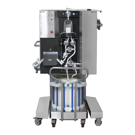
3 System description 3.2 System illustrations System illustrations ÄKTA ready with a flow kit Part Function ÄKTA ready cabinet ReadyToProcess column (ordered separately) ÄKTA ready flow kit (ordered separately) Note: Section 3.5.1 Flow kit overview, on page 37 for more information. Column trolley ÄKTA ready Operating Instructions 28960345 AE... - Page 24 3 System description 3.2 System illustrations ÄKTA ready gradient with a flow kit The gradient pump is an optional component of the ÄKTA ready. Part Function ÄKTA ready gradient pump ÄKTA ready gradient flow section Note: Section 3.5.1 Flow kit overview, on page 37 for more information.
- Page 25 3 System description 3.2 System illustrations ÄKTA ready detailed view The following illustration shows a detailed view of the ÄKTA ready cabinet front. The system is shown with an isocratic flow kit. Part Component ID tag Description PAUSE/ Pressing the button pauses an ongoing process. CONTINUE Pressing second time continues the process.
- Page 26 3 System description 3.2 System illustrations Part Component ID tag Description Stops the pump and places the system in Pause EMERGENCY mode. STOP button Handle Used to move the system. P-201 System pump Peristaltic pump for buffer and sample input. XV-001 to Inlet valves Six valves for liquid input.
- Page 27 3 System description 3.2 System illustrations Position Description FLOW KIT All valves are open. The user can manually open and close the INSTALL valve safety locks. All valves are engaged and controlled by UNICORN. The user cannot open the valve safety locks. COLUMN The valves between air trap outlet and column inlet are open.
-
Page 28: System Components
3 System description 3.3 System components System components Introduction This section provides the overview of ÄKTA ready components. For further details and specifications refer to the documentation package provided with the system. In this section Section See page 3.3.1 Skid and electrical cabinet 3.3.2 Pumps 3.3.3... -
Page 29: Skid And Electrical Cabinet
3 System description 3.3 System components 3.3.1 Skid and electrical cabinet 3.3.1 Skid and electrical cabinet Skid and cabinet The ÄKTA ready hardware consists of a stainless steel cabinet that is placed on a skid. The stainless steel cabinet contains electrical and pneumatic components, and the control unit. -
Page 30: Pumps
3 System description 3.3 System components 3.3.2 Pumps 3.3.2 Pumps Description ÄKTA ready is equipped with one or two pumps depending on the configuration. • Pump P-201 is used for isocratic operation. • Pumps P-201 and P-202 are used for gradient operation. The pump is a peristaltic pump with the capacity up to 510 L/h at a back pressure up to 4 bar g. -
Page 31: Valves
3 System description 3.3 System components 3.3.3 Valves 3.3.3 Valves Pinch valves Pinch valves are used to control the path of the liquid through the flow kit. The valves have manually operated safety locks keeping the tubing in place and preventing the valves from accidentally closing during the flow kit installation. - Page 32 3 System description 3.3 System components 3.3.3 Valves When the system is set to the Pause mode, the air trap valves remain in the same posi- tion as during the run. The user can change this setting in the System Settings in UNICORN.
-
Page 33: System Transmitters And Sensors
3 System description 3.3 System components 3.3.4 System transmitters and sensors 3.3.4 System transmitters and sensors Introduction This section describes the transmitters delivered with the system. for information about transmitters and Section 3.5.2 Flow kit sensors, on page 43 sensors delivered with the flow kit. Flow meter The flow meter, FE-141, measures the liquid velocity using ultrasound. -
Page 34: Flowchart
3 System description 3.4 Flowchart Flowchart Flowchart illustration The following illustration shows a schematic diagram of the ÄKTA ready flow path. HV-301 XV-056 P-202 XV-055 AT-221 XV-054 XV-053 XV-052 PT-111 PT-112 FE-141 AE-131 PT-113 XV-051 XV-001 P-201 XV-002 AE-121 TE-161 CE-101 XV-003 XV-004 XV-005... - Page 35 3 System description 3.4 Flowchart Label Description PT-111 to PT-113 Pressure sensors TE-161 Temperature sensor XV-001 to XV-006 Buffer A inlet valves XV-051 to XV-056 Outlet valves Pressure limits The table below specifies the maximum operating pressure of parts A to D in the flow path, as shown in the flowchart.
-
Page 36: Flow Kits
3 System description 3.5 Flow kits Flow kits Introduction This chapter provides descriptions of the disposable flow kits and an overview of the components. The flow kit specifications are described in the product documentation provided with each flow kit. In this section Section See page 3.5.1... -
Page 37: Flow Kit Overview
3 System description 3.5 Flow kits 3.5.1 Flow kit overview 3.5.1 Flow kit overview Description ÄKTA ready can be used for isocratic or gradient operation. The table below shows the flow kit components needed for these operations. Operation mode Required flow kit parts Isocratic •... - Page 38 3 System description 3.5 Flow kits 3.5.1 Flow kit overview Part Component ID tag Description Air vent tubing Air flow to and from the air trap. Manually controlled by the AIR VENT button through valve HV-301. AT-221 Air trap Allows removal of air from buffers and sample. Manually filled with liquid by pressing the AIR VENT button (air is released).
- Page 39 3 System description 3.5 Flow kits 3.5.1 Flow kit overview Part Component ID tag Description PT-112 Pressure sensor Measures the post-column pressure. Part of the safety monitoring of the medium pressure. AE-121 pH electrode The sensor for pH measurement (optional). The elec- (optional) trode is attached to the flow cell of pressure sensor PT-112, replacing the dummy electrode in the holder.
- Page 40 3 System description 3.5 Flow kits 3.5.1 Flow kit overview Part Component ID tag Description Air vent tubing Air flow to and from the air trap. Manually controlled by the AIR VENT button through valve HV-301. AT-221 Air trap Allows removal of air from buffers and sample. Manually filled with liquid by pressing the AIR VENT button (air is released).
- Page 41 3 System description 3.5 Flow kits 3.5.1 Flow kit overview Part Component ID tag Description XV-001 to Inlet manifold Manifold for liquid input. The six inlets correspond to XV-006 valves XV-001 to XV-006. Gradient pump Liquid input using a peristaltic pump. tubing Note: This tubing is installed in the gradient pump (P-202)
- Page 42 3 System description 3.5 Flow kits 3.5.1 Flow kit overview The following illustration shows the gradient flow section. Delivery of flow kits All parts of the flow kit are delivered in double plastic bags and are pre-treated with gamma radiation or autoclaving. Flow kit components are labeled and equipped with bar codes.
-
Page 43: Flow Kit Sensors
3 System description 3.5 Flow kits 3.5.2 Flow kit sensors 3.5.2 Flow kit sensors Introduction This section describes sensors that are part of the flow kit. For further details see the product documentation package provided with the system. Section 3.3.4 System transmitters and sensors, on page 33 for information about transmitters and sensors delivered with the system. - Page 44 3 System description 3.5 Flow kits 3.5.2 Flow kit sensors Pressure Location Function sensor PT-112 In the medium pressure flow Measures the pressure in the path, downstream of the flow path after the column. The column. difference between pressures at PT-111 and PT-112 is the pressure drop over the column and the packed bed.
-
Page 45: Unicorn Control System
Information on how to use UNICORN can be obtained from the UNICORN documenta- tion and available tutorials. Contact your local Cytiva representative for advice if required. System operators are responsible for designing methods which conform to standard operating procedures and Good Manufacturing Practice procedures. - Page 46 3 System description 3.6 UNICORN control system Software modules The UNICORN control software consists of four modules. Module Function Administration File handling and administration tasks, for example definition of systems and managing user profiles. Method Editor Method creation and editing of preprogrammed control of the system.
-
Page 47: Installation
This chapter describes how to transport and install ÄKTA ready. The components are either fitted on the system or provided as part of the flow kit. Installation must be performed by experienced personnel authorized by Cytiva. In this chapter Section... -
Page 48: Safety Precautions
4 Installation 4.1 Safety precautions Safety precautions WARNING The product must be installed and prepared by Cytiva personnel or a third party authorized by Cytiva. WARNING Move transport crates. Make sure that the lifting equipment has the capacity to safely lift the crate weight. Make sure that the crate is properly balanced so that it does not accidentally tip when moved. - Page 49 4 Installation 4.1 Safety precautions WARNING Protective ground. The product must always be connected to a grounded power outlet. WARNING Supply voltage. Before connecting the power cord, make sure that the supply voltage provided in the facility corresponds to the supply voltage required for the system.
- Page 50 NOTICE ÄKTA ready must be installed and prepared by personnel from Cytiva or third party authorized by Cytiva. Contact Cytiva if you require re-installation at a new site. NOTICE Disconnect power. To prevent damage to the system, always disconnect the power from the product before an module is removed or installed, or a cable is connected or disconnected.
-
Page 51: Site Requirements
4 Installation 4.2 Site requirements Site requirements Dimensions of ÄKTA ready Property ÄKTA ready ÄKTA ready gradient Width × Depth × 100 × 80 ×165 cm 116 × 80 × 165 cm Height Weight 230 kg 250 kg Space required at 280 ×... -
Page 52: Included In The Delivery
4 Installation 4.3 Included in the delivery Included in the delivery General ÄKTA ready is delivered with the following components: • System cabinet • Column trolley • Box containing an accessory kit, system documentation folder, and user documen- tation ÄKTA ready is delivered pre-assembled in the transport crate. No specific assembly prior to site installation is required. -
Page 53: Unpacking
4 Installation 4.4 Unpacking Unpacking Introduction This section describes how to unpack ÄKTA ready and the flow kit in a safe way. In this section Section See page 4.4.1 Unpack ÄKTA ready 4.4.2 Unpack the flow kit ÄKTA ready Operating Instructions 28960345 AE... -
Page 54: Unpack Äkta Ready
• For ÄKTA ready gradient: ÄKTA ready gradient Unpacking Instructions (29042082) Check for damage Check the system for damage before starting assembly and installation. If any damage is found, document the damage, and contact your Cytiva representative. ÄKTA ready Operating Instructions 28960345 AE... -
Page 55: Unpack The Flow Kit
4 Installation 4.4 Unpacking 4.4.2 Unpack the flow kit 4.4.2 Unpack the flow kit Flow kit package ÄKTA ready flow kits are delivered in double plastic bags. The flow kit package contains the following items: • Main part of the flow kit •... -
Page 56: Transport
4 Installation 4.5 Transport Transport Release brakes to move ÄKTA ready The ÄKTA ready can be rolled on hard and level surface when brakes on the casters are released. After positioning the system at its designated location, lock the casters. Use the handle to move ÄKTA ready Use the handle on the left side of the cabinet to move the system. - Page 57 4 Installation 4.5 Transport CAUTION Do not attempt to lift the system by the handle on the left side of the system cabinet. The handle is for maneuvering the cabinet on the floor, not for lifting. ÄKTA ready Operating Instructions 28960345 AE...
- Page 58 4 Installation 4.5 Transport Center of gravity The center of gravity for ÄKTA ready is indicated with a dash-dotted vertical line in the drawings below. Note: The center of gravity line is located slightly towards the back of the cabinet. This causes a tipping hazard and must be taken into consideration when moving or lifting the cabinet.
-
Page 59: Connections
4 Installation 4.6 Connections Connections Introduction This section describes how to connect the power, compressed air, computer, and equipment to CUSTOMER I/O connector of the ÄKTA ready. In this section Section See page 4.6.1 Connect power 4.6.2 Connect compressed air 4.6.3 Connect computer 4.6.4... -
Page 60: Connect Power
Power connection NOTICE Do not turn on the MAINS POWER switch before all connections are made. The mains power supply must be connected and configured by authorized service personnel. Contact your Cytiva representative for help. ÄKTA ready Operating Instructions 28960345 AE... -
Page 61: Connect Compressed Air
4 Installation 4.6 Connections 4.6.2 Connect compressed air 4.6.2 Connect compressed air Connection instructions CAUTION Make sure that correct air pressure is always maintained. Too high or too low air pressure may be hazardous and may cause erroneous results and leakage. Follow the instruction to connect the compressed air supply to the system. -
Page 62: Connect Computer
4 Installation 4.6 Connections 4.6.3 Connect computer 4.6.3 Connect computer General The computer must be installed and used according to the instructions provided by the manufacturer of the computer. It is recommended that the computer is dedicated to UNICORN and the related soft- ware. -
Page 63: Connect Equipment To Customer I/O Connector
4 Installation 4.6 Connections 4.6.4 Connect equipment to CUSTOMER I/O connector 4.6.4 Connect equipment to CUSTOMER I/O connector General The CUSTOMER I/O connector is located on the left side of the system cabinet, below the inlet valves. The connector is a 15 pole IP67-proof D-Sub male connector. A corre- sponding female connector containing a screw terminal block with watertight housing is supplied with the system. - Page 64 4 Installation 4.6 Connections 4.6.4 Connect equipment to CUSTOMER I/O connector ÄKTA ready +24 V Pins 11 and 15 (see image below) are used to receive an On signal (B) from an optional UPS during a power failure. ÄKTA ready +24 V Connect air sensors The two air sensors are connected to the CUSTOMER I/O as shown in the illustration...
- Page 65 4 Installation 4.6 Connections 4.6.4 Connect equipment to CUSTOMER I/O connector Customer I/O ÄKTA ready connector Air sensor 1 (Air_AE151) +5 V Black COM5V Green (Test) Signal H Orange Signal V Air sensor 2 (Air_AE152) +5 V Black COM5V Green (Test) Signal H Orange Signal V...
-
Page 66: Finish Installation
4 Installation 4.7 Finish installation Finish installation Establish computer connection Follow the steps below to set up a connection between ÄKTA ready and the computer. Step Action Turn the MAINS POWER switch to I position. Result: The green POWER indicator lamp on the front of the system is turned on. The light flashes slowly when communication with UNICORN is not estab- lished. - Page 67 4 Installation 4.7 Finish installation Install the bar code reader Follow the steps below to install and configure the bar code reader. Note: The installation requires bar codes to be scanned from the Quick Start Guide supplied with the bar code reader. The Quick Start Guide is also available on the bar code manufacturer's website.
-
Page 68: Operation
5 Operation Operation About this chapter This chapter provides the information required to prepare, start, operate, and shut down ÄKTA ready. In this chapter Section See page Safety precautions Start the system and log on to UNICORN Install flow kit Perform a component test Connect a column Set ÄKTA ready specific parameters in Method Editor... -
Page 69: Safety Precautions
WARNING Use columns that withstand expected pressures. If not, the columns might rupture, resulting in injury. Preferably use ReadyTo- Process columns from Cytiva. WARNING Always perform a component test when installing a flow kit. The component test includes verification of the pressure sensors. - Page 70 5 Operation 5.1 Safety precautions WARNING When the system is operated from a remote controlling computer, the operator must always make sure that no one is present and exposed when the system is started and that no one enters the risk area around the system during operation.
- Page 71 5 Operation 5.1 Safety precautions CAUTION Before use, check that the column is not damaged or otherwise defective. Damaged or defective columns may leak. CAUTION Make sure that the waste container is dimensioned for maximum possible volume when the system is left unattended. CAUTION Waste tubes and containers must be secured and sealed to prevent accidental spillage.
- Page 72 5 Operation 5.1 Safety precautions NOTICE Make sure that the temperature of the process liquid is not lower than 10°C below the ambient temperature. Larger temperature differences can cause condensation on the UV sensor cell. ÄKTA ready Operating Instructions 28960345 AE...
-
Page 73: Start The System And Log On To Unicorn
5 Operation 5.2 Start the system and log on to UNICORN Start the system and log on to UNICORN Introduction ÄKTA ready is usually kept switched on between runs. The system is switched off only during monthly maintenance and repair, or when not in operation for a longer period of time (more than a few days). - Page 74 5 Operation 5.2 Start the system and log on to UNICORN Step Action Click OK. In the System Control module, on the System menu, click Connect to Systems. Result: A dialog box opens. In the dialog box, do the following: a.
-
Page 75: Install Flow Kit
5 Operation 5.3 Install flow kit Install flow kit Introduction This section describes how to install the flow kit and the gradient flow section. In this section Section See page 5.3.1 Safety precautions 5.3.2 Prepare for flow kit installation 5.3.3 Create flow kit installation method 5.3.4 Install the flow kit for isocratic run... -
Page 76: Safety Precautions
5.3.1 Safety precautions 5.3.1 Safety precautions NOTICE Only use flow kits supplied by Cytiva. NOTICE Always perform a flow kit installation test when installing a flow kit. The test includes verification of the sensors. ÄKTA ready Operating Instructions 28960345 AE... -
Page 77: Prepare For Flow Kit Installation
5 Operation 5.3 Install flow kit 5.3.2 Prepare for flow kit installation 5.3.2 Prepare for flow kit installation Before flow kit installation • Locate the two TC clamps and gaskets supplied with the flow kit. Prepare three additional clamps and gaskets (not supplied) that are required to install the flow kit and run a component test. - Page 78 5 Operation 5.3 Install flow kit 5.3.2 Prepare for flow kit installation Step Action In the Edit dialog box, select the following check boxes as applicable for your system and process. Note: Äkta_Ready is selected by default. a. Äkta_Ready_Gradient, if your are working with ÄKTA ready gradient system.
- Page 79 5 Operation 5.3 Install flow kit 5.3.2 Prepare for flow kit installation Step Action Click OK to close the dialog box. ÄKTA ready Operating Instructions 28960345 AE...
-
Page 80: Create Flow Kit Installation Method
5 Operation 5.3 Install flow kit 5.3.3 Create flow kit installation method 5.3.3 Create flow kit installation method Create method The user must simultaneously create the flow kit installation method and install the flow kit. Follow the instructions in an applicable manual section to install the flow kit. •... - Page 81 5 Operation 5.3 Install flow kit 5.3.3 Create flow kit installation method Step Action Save the created flow kit installation method. ÄKTA ready Operating Instructions 28960345 AE...
-
Page 82: Install The Flow Kit For Isocratic Run
5 Operation 5.3 Install flow kit 5.3.4 Install the flow kit for isocratic run 5.3.4 Install the flow kit for isocratic run Introduction The following sections contain a step-by-step description how to install the flow kit for an isocratic run. The short outline of the procedure is also included as Flow Kit Instal- lation in the ÄKTA ready Installation Wizard. - Page 83 5 Operation 5.3 Install flow kit 5.3.4 Install the flow kit for isocratic run Open safety locks on pinch valves The safety locks keep the pinch valves in an open position. Follow the steps below to open the safety locks. Step Action Make sure that UNICORN is in the End mode.
- Page 84 5 Operation 5.3 Install flow kit 5.3.4 Install the flow kit for isocratic run Remove pump lid Step Action Locate the 10 mm wrench on the inside of the cabinet front door. Locate the two bolts holding the pump lid. Rotate the right-hand bolt counterclockwise, and the left-hand bolt clock- wise using the wrench, until both bolts are fully open.
- Page 85 5 Operation 5.3 Install flow kit 5.3.4 Install the flow kit for isocratic run Step Action ÄKTA ready Operating Instructions 28960345 AE...
- Page 86 5 Operation 5.3 Install flow kit 5.3.4 Install the flow kit for isocratic run Open pressure sensor holders Step Action Locate the three pressure sensor holders for pressure sensors PT-111, PT-112, and PT-113. PT-113 PT-111 PT-112 Loosen the screws on the latches, and turn the latches to open position. Do not remove the screws.
- Page 87 5 Operation 5.3 Install flow kit 5.3.4 Install the flow kit for isocratic run Attach the inlet manifold Step Action Open the bag containing the inlet manifold and the main part of the flow kit. Attach the inlet manifold to the system: insert each inlet tubing into the corresponding inlet pinch valve (XV-001 to XV-006).
- Page 88 5 Operation 5.3 Install flow kit 5.3.4 Install the flow kit for isocratic run Attach the main part tubing Step Action Lift the main part of the flow kit (see the illustration): • Hold the air trap (1) in your left hand. •...
- Page 89 5 Operation 5.3 Install flow kit 5.3.4 Install the flow kit for isocratic run Step Action Take the pump tubing out of the flow kit package. Place the tubing on top of the pump rollers of the isocratic pump. The larger connector block (for connection with the main part of the flow kit) must be to the right of the pump.
- Page 90 5 Operation 5.3 Install flow kit 5.3.4 Install the flow kit for isocratic run Step Action Connect the connector on right side of the pump tubing to the flow kit using a TC clamp. Connect the connector on left side to the inlet manifold using a TC clamp. Attach the pump lid Step Action...
- Page 91 5 Operation 5.3 Install flow kit 5.3.4 Install the flow kit for isocratic run Step Action Verify the position of the pegs at the back of the lid. The pegs must be in their lowermost position when the lid is closed. The system cannot work if the lid is not properly attached.
- Page 92 5 Operation 5.3 Install flow kit 5.3.4 Install the flow kit for isocratic run Install tubing and sensors Step Action Insert the tubing into the valves in the order specified below. Close the valve safety lock on each valve after inserting the tubing. a.
- Page 93 5 Operation 5.3 Install flow kit 5.3.4 Install the flow kit for isocratic run Step Action Push the three pressure sensors into their respective holders on the cabinet (sensors PT-111, PT-112, and PT-113). Attach the pressure sensors to the cabinet: turn the latch over the pressure sensor body and loosely fasten the screws (4, 5).
- Page 94 5 Operation 5.3 Install flow kit 5.3.4 Install the flow kit for isocratic run Step Action Align the holes in the body of the flow meter (FE-141) with the two knobs on the cabinet (7 and 8 in the illustration), and push the flow meter onto the knobs.
- Page 95 5 Operation 5.3 Install flow kit 5.3.4 Install the flow kit for isocratic run Step Action Screw the conductivity sensor cable into the connector on the system cabinet. Note: Do not use force when inserting the connector. Attach the outlet manifold Step Action Attach the outlet manifold (3) to the system: insert each inlet tubing into the...
- Page 96 5 Operation 5.3 Install flow kit 5.3.4 Install the flow kit for isocratic run Step Action Close the safety locks on all pinch valves: lift each black handle and turn the handle inward 180 degrees. Push the air vent tubing (attached to the top of the air trap) onto the holder (1) on top of the system cabinet.
- Page 97 5 Operation 5.3 Install flow kit 5.3.4 Install the flow kit for isocratic run Install the pH electrode Step Action Unscrew the plastic fastening nut (2) on top of pressure sensor (PT-112) and pull out the dummy (3) from the electrode holder. AE-121 PT-112 Locate the pH cable on the system cabinet (in the storage position), and...
- Page 98 It is possible to assemble the flow kit parts in a laminar flow cabinet, and then install the assembled kit on the ÄKTA ready system. Although this procedure may decrease the possibility for microbial contamination, Cytiva does not recommend the procedure. The pre-assembly may lead to incorrect orientation of the flow kit parts and cause tensions or damage the flow kit.
- Page 99 5 Operation 5.3 Install flow kit 5.3.4 Install the flow kit for isocratic run If pre-assembling the flow kit, make sure that the flow kit parts are correctly oriented towards each other and towards the ÄKTA ready system (for example, the inlet and outlet manifolds must be correctly oriented).
-
Page 100: Install The Flow Kit For Gradient Run
5 Operation 5.3 Install flow kit 5.3.5 Install the flow kit for gradient run 5.3.5 Install the flow kit for gradient run Introduction The following sections contain a step-by-step description on how to install the flow kit for a gradient run, including the gradient flow section. The short outline of the proce- dure is also included as Flow Kit Installation in the ÄKTA ready Installation Wizard. - Page 101 5 Operation 5.3 Install flow kit 5.3.5 Install the flow kit for gradient run Step Action Take the pump tubing out of the isocratic flow kit package. Place the pump tubing on the gradient pump rollers (pump P-202). The larger connector block (for connection with the main part of the flow kit) must be to the right of the pump.
- Page 102 5 Operation 5.3 Install flow kit 5.3.5 Install the flow kit for gradient run Step Action Stretch the tubing, and push it over the knob on the left side. Take the pump tubing and the jumper tubing out of the gradient flow section package.
- Page 103 5 Operation 5.3 Install flow kit 5.3.5 Install the flow kit for gradient run Step Action Connect the jumper tubing to the right side of the pump tubing on the gradient pump (P-202) using a TC clamp. Connect the other end of the jumper tubing to the right side of the pump tubing on the isocratic pump (P-201).
- Page 104 5 Operation 5.3 Install flow kit 5.3.5 Install the flow kit for gradient run Step Action Install the conductivity sensor and the pH electrode (see Install the pH elec- trode, on page 97). Attach the outlet manifold (see Attach the outlet manifold, on page 95).
-
Page 105: Perform A Component Test
5 Operation 5.4 Perform a component test Perform a component test Introduction This section gives instructions on how to perform the component test, and describes the test report. In this section Section See page 5.4.1 Run a component test 5.4.2 The test report Safety precautions NOTICE... -
Page 106: Run A Component Test
5 Operation 5.4 Perform a component test 5.4.1 Run a component test 5.4.1 Run a component test Introduction The component test is an option that can be included in the flow kit installation method. See Create method, on page 80 for details. - Page 107 5 Operation 5.4 Perform a component test 5.4.1 Run a component test Step Action Remove the protective end cap from Inlet 6, and connect the wash solution. Note: Containers must not be placed lower than 1 m below the inlets (that is, floor level).
- Page 108 5 Operation 5.4 Perform a component test 5.4.1 Run a component test Run the component test The component test is created as part of the flow kit installation method. All informa- tion added by the user (for example notes) is included in the test report. Running a component test takes about 10 minutes.
- Page 109 5 Operation 5.4 Perform a component test 5.4.1 Run a component test Actions during a component test The test progress can be followed in the UNICORN System Control module. Charts show the response curves for the different sensors. The software issues two messages during the test run. 1.
-
Page 110: The Test Report
5 Operation 5.4 Perform a component test 5.4.2 The test report 5.4.2 The test report Print the test report Information about an installation, including the results from the component test, are stored and can be compiled into a printed report. The report can be printed from the Evaluation Classic module. -
Page 111: Connect A Column
5 Operation 5.5 Connect a column Connect a column Introduction This section describes how to install a column on the system. The information in this section is also available in Column Installation in the ÄKTA ready installation wizard. The section also contains instructions for running a column efficiency test and for column rinsing. -
Page 112: Install A Column
Overpressure. Never block the outlet tubing with stop plugs or other items. This creates overpressure and may cause injury. Contact a local Cytiva representative for more information about using products other than ReadyToProcess columns with ÄKTA ready. More information about columns and chromatography resin is found on the Cytiva website. - Page 113 5 Operation 5.5 Connect a column 5.5.1 Install a column Position the column CAUTION Before use, check that the column is not damaged or otherwise defective. Damaged or defective columns may leak. Follow the steps below to position the column correctly. Step Action Place the column on the column trolley.
- Page 114 5 Operation 5.5 Connect a column 5.5.1 Install a column Step Action Roll the trolley into position between the system cabinet leg supports, and lock the trolley wheels (2). Note: Be careful when transporting smaller columns (for example 2.5 L) on the trolley.
- Page 115 5 Operation 5.5 Connect a column 5.5.1 Install a column Step Action In the Method Wizard, select the following options: a. Gradient or Isocratic, depending on your system. b. Include Efficiency Test of Column (optional). c. Include Rinsing of Column (optional) d.
- Page 116 5 Operation 5.5 Connect a column 5.5.1 Install a column Step Action Click Next to move to the next page in the Method Wizard. a. On each new page select and confirm the options as applicable for your system, and then click Next. b.
- Page 117 5 Operation 5.5 Connect a column 5.5.1 Install a column Connect the column Follow the instructions in the Method Wizard, as described in Create column installa- tion method, on page 114, to connect the column and create the optional test methods.
- Page 118 5 Operation 5.5 Connect a column 5.5.1 Install a column Step Action Turn the installation switch to the COLUMN INSTALL position. Result: The flow path from the air trap to the column opens. Let the liquid flow from the air trap into the column. Press the AIR VENT button on the system cabinet front to open the air trap and release the air.
- Page 119 5 Operation 5.5 Connect a column 5.5.1 Install a column Step Action Turn the installation switch to the RUN position. ÄKTA ready Operating Instructions 28960345 AE...
-
Page 120: Run A Column Efficiency Test (Optional)
5 Operation 5.5 Connect a column 5.5.2 Run a column efficiency test (optional) 5.5.2 Run a column efficiency test (optional) General A column efficiency test can be included when creating the column installation method with the installation wizard (see Create column installation method, on page for more information). - Page 121 5 Operation 5.5 Connect a column 5.5.2 Run a column efficiency test (optional) Step Action In the System Control module, click File →Open, and select the applicable method. Result: The Start Protocol window opens. On the Notes tab, verify the information. Type your input as applicable, and then click Next to continue.
- Page 122 5 Operation 5.5 Connect a column 5.5.2 Run a column efficiency test (optional) Step Action In the dialog box, select the format AKTAready_Column_T (1). Note: This format is specifically adapted for the column test report. Click Print or Preview (2) as applicable. A column test report does not state if the column has passed or failed the test.
-
Page 123: Rinse A Column (Optional)
5 Operation 5.5 Connect a column 5.5.3 Rinse a column (optional) 5.5.3 Rinse a column (optional) Introduction The rinsing methods can be predefined or customized by the user. The predefined method is included as an optional step in the column installation wizard (see Create column installation method, on page 114). -
Page 124: Set Äkta Ready Specific Parameters In Method Editor
5 Operation 5.6 Set ÄKTA ready specific parameters in Method Editor Set ÄKTA ready specific parameters in Method Editor Introduction This section describes how to change specific features for ÄKTA ready in the UNICORN Method Editor. The changes are applied to existing methods. See UNICORN manuals for instructions on how to create methods. -
Page 125: Set Uv Stray Light Calibration
5 Operation 5.6 Set ÄKTA ready specific parameters in Method Editor 5.6.1 Set UV stray light calibration 5.6.1 Set UV stray light calibration Introduction The UV sensor is automatically calibrated when a new flow kit is installed using the installation wizard. In addition, manual calibration of the UV sensor can also be included in the methods. - Page 126 5 Operation 5.6 Set ÄKTA ready specific parameters in Method Editor 5.6.1 Set UV stray light calibration Step Action Click Insert (2). When the method is executed and the stray light calibration starts, the following message is shown: Stray light reduction calibration. Do not perform any other instruc- tion during the next 15 seconds.
-
Page 127: Set Flow Meter Fine Tuning
5 Operation 5.6 Set ÄKTA ready specific parameters in Method Editor 5.6.2 Set flow meter fine tuning 5.6.2 Set flow meter fine tuning Introduction The flow meter uses ultrasound to measure the flow rate. Fine tuning is used to correct the measured flow rate for differences in sound speed through plastic and liquid. -
Page 128: Set Totalizers
5 Operation 5.6 Set ÄKTA ready specific parameters in Method Editor 5.6.3 Set totalizers 5.6.3 Set totalizers Introduction A totalizer monitors the accumulated volumes passing through an inlet or an outlet. Every inlet or outlet has a specific totalizer. Set totalizer Follow the steps below to set or reset a totalizer, or activate a totalizer alarm. - Page 129 5 Operation 5.6 Set ÄKTA ready specific parameters in Method Editor 5.6.3 Set totalizers Step Action To activate an alarm for an enabled totalizer, do the following: a. Expand Alarms&Mon b. Scroll down, and then click Alarm_Inlet1_Totalizer. c. On the Setpoint list, select an applicable volume (1.0 to 500 L). d.
-
Page 130: Set Pressureflowcontrol
5 Operation 5.6 Set ÄKTA ready specific parameters in Method Editor 5.6.4 Set PressureFlowControl 5.6.4 Set PressureFlowControl Introduction The PressureFlowControl functionality is used to set limits to pressure and flow rate. The functionality adjusts the flow rate to maintain the defined pressure, or maintains the defined flow rate. - Page 131 5 Operation 5.6 Set ÄKTA ready specific parameters in Method Editor 5.6.4 Set PressureFlowControl Step Action On the Instructions list, click PressureFlowLimit (4). Result: The parameters for the function are displayed. On the Flow+ list (5), select an applicable value for flow rate deviation (0.0 to 100 l/hour).
- Page 132 5 Operation 5.6 Set ÄKTA ready specific parameters in Method Editor 5.6.4 Set PressureFlowControl Step Action Click Disabled (2). Click Insert (3). ÄKTA ready Operating Instructions 28960345 AE...
-
Page 133: Run A Method
5 Operation 5.7 Run a method Run a method Introduction This section describes how to start, monitor and end a method run. Running a method on ÄKTA ready is automated. User interaction is required in the preparation phase (for example connecting the column and containers, checking connections and the flow kit). -
Page 134: Prepare Before A Run
5 Operation 5.7 Run a method 5.7.1 Prepare before a run 5.7.1 Prepare before a run Safety precautions WARNING Hazardous substances and biological agents. When using hazardous chemical and biological agents, take all suitable protec- tive measures, such as wearing protective clothing, glasses and gloves resistant to the substances used. - Page 135 5 Operation 5.7 Run a method 5.7.1 Prepare before a run Connect containers Connect the containers shown in the table below. Container Action Buffers Connect the buffer inlet tubing to the appropriate buffer containers. The liquid level in the inlet containers should be equal, and similarly equal in the outlet containers.
- Page 136 5 Operation 5.7 Run a method 5.7.1 Prepare before a run Set valve switch time The valve switch time is a short period when two inlet valves or two outlet valves are open simultaneously, as the flow is switched from one valve to another. This allows the pump to run continuously without a blocked flow due to a closed inlet or outlet mani- fold.
- Page 137 5 Operation 5.7 Run a method 5.7.1 Prepare before a run Set OutletCloseTime The OutletCloseTime function specifies the length of the time delay before the outlet valves are closed. This allows the system to get depressurized when the method ends. Follow the steps below to set the OutletCloseTime.
- Page 138 5 Operation 5.7 Run a method 5.7.1 Prepare before a run • Make sure that the entire flow path, including the tubing to inlet containers, is filled with liquid and that no air bubbles remain in the system. If air reaches the flow meter during a run, a message Uncertain flow is displayed, and the system goes to Pause mode.
- Page 139 5 Operation 5.7 Run a method 5.7.1 Prepare before a run ÄKTA ready Operating Instructions 28960345 AE...
- Page 140 5 Operation 5.7 Run a method 5.7.2 Run a method 5.7.2 Run a method Start a run Follow the steps below to start a run. Step Action In the System Control module, click File →Open. In the Method Navigator pane, double-click the applicable method. Result: The Start Protocol window opens.
- Page 141 5 Operation 5.7 Run a method 5.7.2 Run a method Monitor a run The progress of the run can be viewed in detail in the UNICORN System Control module. Up to four separate panes can be displayed simultaneously to show different aspects of the run.
- Page 142 5 Operation 5.7 Run a method 5.7.2 Run a method View results The results can be viewed and saved using a UNICORN evaluation module. Two evalua- tion modules are available: Evaluation and Evaluation Classic. Only the Evaluation Classic module supports report formats that are linked to the Method Wizard. See specific UNICORN manuals for more information about viewing results and customizing the result layout.
-
Page 143: Controlled Shutdown
5 Operation 5.8 Controlled shutdown Controlled shutdown Remove flow kit and column WARNING Hazardous biological agents during a run. After using hazardous biological agents flush the whole system tubing with a bacteriostatic solution, neutral buffer, and then water before doing service or maintenance. - Page 144 5 Operation 5.8 Controlled shutdown Step Action Turn the installation switch to the FLOW KIT INSTALL position. Remove all flow kit sensors from their holders or connectors. Clean the contact surfaces of the flow meter connectors. Open the safety locks on all pinch valves: lift the black handle of the valve safety lock and turn the handle outward 180 degrees.
- Page 145 5 Operation 5.8 Controlled shutdown Step Action Turn the MAINS POWER switch to the O position. ÄKTA ready Operating Instructions 28960345 AE...
-
Page 146: Maintenance
6 Maintenance Maintenance About this chapter This chapter provides schedules and instructions for preventive maintenance that should be performed by the user of the ÄKTA ready system. Instructions for spare part replacement, calibration, and cleaning are also provided. In this chapter Section See page Safety precautions... -
Page 147: Safety Precautions
WARNING Use only approved parts. Only spare parts and accessories that are approved or supplied by Cytiva may be used for maintaining or servicing the product. WARNING Electrical shock hazard. All installation, service and maintenance of components inside the electronics cabinet must be done by service personnel authorized by Cytiva. - Page 148 6 Maintenance 6.1 Safety precautions WARNING Disconnect power. Always disconnect power before resetting circuit breakers. WARNING Hazardous biological agents during a run. After using hazardous biological agents flush the whole system tubing with a bacteriostatic solution, neutral buffer, and then water before doing service or maintenance.
-
Page 149: Maintenance Schedule
Cytiva representative. Preventive service must be performed annually by qualified service personnel author- ized by Cytiva. Contact your local Cytiva representative for more information about the available service agreements. Any abnormal behavior or aberrant noise must be examined and rectified. -
Page 150: Maintenance Procedures
6 Maintenance 6.3 Maintenance procedures Maintenance procedures Apply lubricant to flow meter If the warning Fine_tuning_flow_meter_failed is displayed in UNICORN, there may be insufficient lubricant between the flow meter and the transducers. Follow the instruction below to apply new lubricant. Step Action Allow the ongoing run to finish. - Page 151 6 Maintenance 6.3 Maintenance procedures Test the temperature sensor The accuracy of the temperature sensor can be tested with the Temperature Test Tool. Contact Cytiva to order the tool. Follow the steps below to test the temperature sensor. Step Action Remove the pH electrode or pH electrode dummy from the pressure sensor PT112.
- Page 152 6 Maintenance 6.3 Maintenance procedures Replace the air filter Check the condition of the air filter regularly, it can become clogged under extreme conditions. If the filter is dirty, follow the steps below to replace it. Step Action Locate the filter beneath the cabinet front panel (arrow in the illustration). Remove the filter cover and the filter by unscrewing the six nuts (see the illustration below).
- Page 153 6.3 Maintenance procedures Pump head maintenance Changes in vibration or sound of the pump can indicate that pump components need to be replaced. Contact your local Cytiva service engineer to change pump compo- nents. Replace wheels Before replacing a wheel, carefully read the instructions about lifting and moving the system, see Section 4.5 Transport, on page...
-
Page 154: Calibration
6 Maintenance 6.4 Calibration Calibration Introduction This section describes how to calibrate the sensors and the gradient pump. In this section Section See page 6.4.1 Calibrate sensors 6.4.2 Calibrate the gradient pump ÄKTA ready Operating Instructions 28960345 AE... -
Page 155: Calibrate Sensors
6 Maintenance 6.4 Calibration 6.4.1 Calibrate sensors 6.4.1 Calibrate sensors Introduction This section describes how to calibrate the conductivity sensor, the flow meter, the pH electrode, and the pressure sensors. Calibrate the conductivity sensor Calibration of the conductivity sensor is generally not needed, because the standard setting of the cell constant that is used in UNICORN, is applicable for the most applica- tions. - Page 156 6 Maintenance 6.4 Calibration 6.4.1 Calibrate sensors Step Action In the System Control module, click System →Calibrate. In the Calibration window, on the Monitor to calibrate list, select Cond_Calibr (3). Read the conductivity value in the Current value text box (4). ÄKTA ready Operating Instructions 28960345 AE...
- Page 157 6 Maintenance 6.4 Calibration 6.4.1 Calibrate sensors Step Action Read the theoretical conductivity value on the graph below, and compare the measured value with the theoretical value. Temperature (°C) • If the measured value corresponds to the theoretical value, no further action is needed.
- Page 158 6 Maintenance 6.4 Calibration 6.4.1 Calibrate sensors Step Action Type the theoretical conductivity value in the Set the reference value box (5). Click Read value 1 (6). Result: The new conductivity cell constant is automatically calculated and updated. ÄKTA ready Operating Instructions 28960345 AE...
- Page 159 6 Maintenance 6.4 Calibration 6.4.1 Calibrate sensors Calibrate the flow meter The flow meter needs to be recalibrated (zero adjustment) when the flow readings differ from zero under no flow conditions (for example, when the system is in the End state), or when there is a difference between calculated and actual liquid consumption caused by zero point offset.
- Page 160 6 Maintenance 6.4 Calibration 6.4.1 Calibrate sensors Step Action Rinse the pH electrode with purified water and place the pH electrode in the first standard solution. Type the pH of the standard solution in the first Set the reference value box (1), and wait for the current pH value to stabilize (2).
- Page 161 A pressure calibration cell and pump are needed for the calibration. Contact your Cytiva representative for ordering information. It is recommended to calibrate the pressure sensors without a flow kit attached to the system. Follow the steps below to perform the calibration.
- Page 162 6 Maintenance 6.4 Calibration 6.4.1 Calibrate sensors Step Action Install the calibration cell on pressure meter PT-111 (a calibration cell without the pump tubing is shown in the illustration). Apply up to 5 bar g pressure to the pressure sensor a few times until the reading at atmospheric pressure is stable.
- Page 163 6.4.1 Calibrate sensors Step Action Remove the calibration cell. Make sure that the pressure reading is ≤ -0.20 bar g. If the reading is higher, contact Cytiva. Result: PT-111 is calibrated. Repeat the calibration procedure with pressure sensors PT-112 and PT-113.
-
Page 164: Calibrate The Gradient Pump
6 Maintenance 6.4 Calibration 6.4.2 Calibrate the gradient pump 6.4.2 Calibrate the gradient pump Description The calibration procedure compensates for differences in capacity of pump A (P-201) and pump B (P-202) at a given speed due to the pump tubing position and properties. The flow rate and the pump speed (rpm) are linearly proportional. - Page 165 6 Maintenance 6.4 Calibration 6.4.2 Calibrate the gradient pump Step Action Start the isocratic pump manually: a. In the Instructions box, expand Pump. b. Select ManFlow, and then set the ManFlow value to 50%. c. Click Insert, and then click Execute. Run the pump until the flow rate is stable.
- Page 166 6 Maintenance 6.4 Calibration 6.4.2 Calibrate the gradient pump Step Action Set the flow rate: a. Expand Pump, select Gradient, and then set Target to 0% B. b. Select Flow. c. Set the FlowRate to at least 20 L/h for LowFlow Kit and 40 L/h for High- Flow Kit d.
- Page 167 6 Maintenance 6.4 Calibration 6.4.2 Calibrate the gradient pump Step Action Set the P-201 pump instruction: a. Expand Pump, and select P201Gain. b. Click Execute. c. Select Gradient, and set Target to 100% B. d. Click Execute. Wait until the flow rate is stable. ÄKTA ready Operating Instructions 28960345 AE...
- Page 168 6 Maintenance 6.4 Calibration 6.4.2 Calibrate the gradient pump Step Action Set the P-202 pump instruction: a. Expand Pump, and select P202Gain. b. Click Execute. c. Select FlowCompensation, and then select ON. Note: FlowCompensation is switched off when a manual run or a method run ends.
- Page 169 6 Maintenance 6.4 Calibration 6.4.2 Calibrate the gradient pump Activate flow compensation factor The FlowCompensation function must be activated for each run that uses a cali- brated P-202 pump. Follow the steps below to activate the function. Step Action In the System Control module, click Manual →Execute Manual Instruc- tion.
-
Page 170: Cleaning
6 Maintenance 6.5 Cleaning Cleaning Safety precautions CAUTION To avoid contamination, make sure the system is thoroughly cleaned before changing the flow kit. CAUTION Connectors on the system (for example connectors for pH, conduc- tivity, network) that are not used, must be plugged to prevent cleaning liquid from entering the connector. - Page 171 6 Maintenance 6.5 Cleaning • If NaOH was used, rinse the system with a neutralizing buffer before rinsing it with water. Note: Rinsing the system with water directly after cleaning with NaOH causes the tubing inner walls to stick together. •...
-
Page 172: Storage
6 Maintenance 6.6 Storage Storage Prepare for storage If the system is stored for a period of more than a few days, perform the following: • Remove the flow kit (see Remove flow kit and column, on page 143). • Clean the cabinet (see Cleaning, on page 170). -
Page 173: Troubleshooting
Section 7.2 Troubleshooting a failed component test, on page 181. If the suggested actions in this guide do not solve the problem or if the problem is not covered by this guide, contact your Cytiva representative. In this chapter Section See page... -
Page 174: Troubleshooting The System
7 Troubleshooting 7.1 Troubleshooting the system Troubleshooting the system Air in flow path Problem Corrective action Air enters the flow path. The Identify the cause, for example, damaged tubing or connector, a alarm Uncertain flow is dislocated TC gasket, or inlet tubing not properly located in liquid. displayed and the system In rare cases, cavitation due to negative pressure can cause air to enters Pause mode. - Page 175 7 Troubleshooting 7.1 Troubleshooting the system Computer Problem Corrective action No system found when starting 1. Make sure the system is switched on. up UNICORN. 2. Check communication cable and connectors. 3. If system is connected to a switch or hub, check that the cross- over cable (3 m) is connected in series with the long (10 m) cable.
- Page 176 7 Troubleshooting 7.1 Troubleshooting the system Problem Corrective action Errors in temperature readings. The conductivity measurement is temperature compensated and is dependent on correct temperature measurements. 1. Loosen the flow meter. Verify that the flow meter is properly pushed onto the two knobs (see Install tubing and sensors, on page 92).
- Page 177 7 Troubleshooting 7.1 Troubleshooting the system Problem Corrective action Cavitation (small air bubbles In rare cases, cavitation due to negative pressure can cause air to produced by under-pressure), enter the flow path. Cavitation can be recognized by a hissing which results in unstable flow noise.
- Page 178 7.1 Troubleshooting the system Problem Corrective action Fuse blows repeatedly. Shut the ÄKTA ready down using the main switch and contact your local Cytiva representative. Pressure sensors Problem Corrective action Incorrect pressure measure- • Make sure that the pressure sensor is correctly aligned in the ment.
- Page 179 • Check if the pump rotor is slipping on the drive shaft. Contact Cytiva service personnel for reparation. Pulsation of liquid in flow kit. • Check that the viscosity of liquid is within specified range. Refer to the General Specifications.
- Page 180 7 Troubleshooting 7.1 Troubleshooting the system Valves Problem Corrective action The message Valve error is A valve lock may be open. Check the valve locks and close them. displayed. Note: Before closing the manual valve lock, make sure the valve is in open position in the software.
-
Page 181: Troubleshooting A Failed Component Test
7 Troubleshooting 7.2 Troubleshooting a failed component test Troubleshooting a failed component test Introduction When a component test fails, a Test Failed message is shown. For troubleshooting a failed component test it is recommended to use the Troubleshooting option in the installation wizard. - Page 182 7 Troubleshooting 7.2 Troubleshooting a failed component test Troubleshoot with installation wizard Follow the steps below to troubleshoot a failed component test using the installation wizard. Step Action In the Method Editor module, click File →New Method. In the New Method dialog box, select Method Wizard, and then click OK. In the wizard, select Troubleshoot Failed Component Test, and then select the applicable check boxes for the previously failed components for additional troubleshooting.
-
Page 183: Reference Information
8 Reference information Reference information About this chapter This chapter provides required information that is useful when installing, operating, maintaining, and troubleshooting the ÄKTA ready system. It also contains ordering information. In this chapter Section See page Specifications Chemical resistance Environmental requirements PID control Recycling information... -
Page 184: Specifications
8 Reference information 8.1 Specifications Specifications System capacity ÄKTA ready ÄKTA ready Property Low Flow Kit High Flow Kit Volumetric flow rates 3 to 175 L/h 7.5 to 510 L/h Pump speed 225 rpm (100%) 340 rpm (100%) Maximal pressure, peri- ≥... -
Page 185: Chemical Resistance
Only the flow kit components are wetted parts. Consider the compatibility of the wetted parts and your process chemicals before using the system. Contact your local Cytiva representative if you are not sure about the compatibility of your process chemicals. - Page 186 8 Reference information 8.2 Chemical resistance Chemical Concentration Guanidine hydrochloride Hydrochloric acid 0.1 M Imidazole Mercaptoethanol 20 mM Pluronic™ F-68 Polyethylene glycol, PEG 500 Polyethylene glycol, PEG 1000 Polyethylene glycol, PEG 5000 Potassium phosphate 1-propanol 2-propanol Sodium acetate Sodium chloride Sodium citrate Sodium sulfate Sodium hydroxide...
-
Page 187: Environmental Requirements
8 Reference information 8.3 Environmental requirements Environmental requirements Environmental specifications The installation site must comply with the following specifications: Process Parameter Specification Operation Allowed location Indoor use only Ambient temperature 2°C to 30°C Relative humidity 20% to 95%, non-condensing Dust-free filtered air Atmospheric pressure 950 to 1050 mbar Storage, system... -
Page 188: Pid Control
8 Reference information 8.4 PID control PID control Introduction PID control is a well established and widely used method for feedback control of processes. This section contains general information about PID control, and how it is used in ÄKTA ready. Principles A PID controller uses the difference (error) between the actual (measured) value and a designated setpoint to calculate the adjustment required for keeping a process within... - Page 189 8 Reference information 8.4 PID control Step Action Click FlowTune (1). Locate the I-parameter that corresponds to your installed flow kit (2): • I_LowFlow for the Low Flow Kit. • I_HighFlow for the High Flow Kit. Change the I-parameter depending on the required change. •...
-
Page 190: Recycling Information
Recycling of hazardous substances The product contains hazardous substances. Detailed information is available from your Cytiva representative. Disposal of electrical components Waste electrical and electronic equipment must not be disposed of as unsorted munic- ipal waste and must be collected separately. - Page 191 8 Reference information 8.5 Recycling information Disposal of flow kit and column Make sure to follow local regulations when disposing of the flow kit and the column. Consult the column documentation for further information about disposing the column. Follow the steps below for disposal of the flow kit and the column. Step Action Disconnect the flow kit and the column as instructed in...
-
Page 192: Regulatory Information
8 Reference information 8.6 Regulatory information Regulatory information Introduction This section lists the regulations and standards that apply to the products. In this section Section See page 8.6.1 Contact information 8.6.2 European Union and European Economic Area 8.6.3 Eurasian Economic Union Евразийский... -
Page 193: Contact Information
Manufacturing information The table below summarizes the required manufacturing information. Requirement Information Name and address of manufacturer Cytiva Sweden AB Björkgatan 30 SE 751 84 Uppsala Sweden Telephone number of manufacturer + 46 771 400 600 ÄKTA ready Operating Instructions 28960345 AE... -
Page 194: European Union And European Economic Area
8 Reference information 8.6 Regulatory information 8.6.2 European Union and European Economic Area 8.6.2 European Union and European Economic Area Introduction This section describes regulatory information for the European Union and European Economic Area that applies to the equipment. Conformity with EU Directives See the EU Declaration of Conformity for the directives and regulations that apply for the CE marking. -
Page 195: Eurasian Economic Union
Presnenskaya nab., 10, fl. 12, pr. III, room 6 Telephone: + 7 495 739 6931 Fax nr: + 7 495 739 6932 E-mail: rucis@cytiva.com Информация о производителе и импортере В следующей таблице приводится сводная информация о производителе и импортере, согласно требованиям Технических регламентов Таможенного союза... - Page 196 Пресненская наб., д. 10, эт. 12, пом. III, ком. 6 Телефон: + 7 495 739 6931 Факс: + 7 495 739 6932 Адрес электронной почты: rucis@cytiva.com Description of symbol on the system label Описание обозначения на этикетке системы This Eurasian compliance mark indicates that the product is...
-
Page 197: Regulations For North America
Note: The user is cautioned that any changes or modifications not expressly approved by Cytiva could void the user’s authority to operate the equip- ment. This equipment has been tested and found to comply with the limits for a Class A digital device, pursuant to part 15 of the FCC Rules. -
Page 198: Regulatory Statements
8 Reference information 8.6 Regulatory information 8.6.5 Regulatory statements 8.6.5 Regulatory statements Additional design considerations For additional design considerations, such as ASME-BPE, GMP and cGMPs information refer to the product-specific specification information provided in the documentation package delivered with each ÄKTA ready. ÄKTA ready Operating Instructions 28960345 AE... -
Page 199: Declaration Of Hazardous Substances (Dohs)
8 Reference information 8.6 Regulatory information 8.6.6 Declaration of Hazardous Substances (DoHS) 8.6.6 Declaration of Hazardous Substances (DoHS) 根据 SJ/T11364-2014《电子电气产品有害物质限制使用标识要求》特提供如下 有关污染控制方面的信息。 The following product pollution control information is provided according to SJ/ T11364-2014 Marking for Restriction of Hazardous Substances caused by electrical and electronic products. - Page 200 8 Reference information 8.6 Regulatory information 8.6.6 Declaration of Hazardous Substances (DoHS) 有害物质的名称及含量 Name and Concentration of Hazardous Substances 产品中有害物质的名称及含量 Table of Hazardous Substances’ Name and Concentration 部件名称 有害物质 Compo- Hazardous substance nent name 铅 汞 镉 六价铬 多溴联苯 多溴二苯醚 (Pb) (Hg) (Cd)
-
Page 201: Flow Kit Ordering Information
Both the isocratic flow kit and the gradient flow kit are available with two tubing diame- ters. The diameter determines the maximum flow rate. For other available flow kit options, see the Cytiva website or contact your local Cytiva representative. Isocratic flow kits... -
Page 202: More Information
• Other issues not covered by this manual Training Cytiva recommends that all new operators attend the training courses available from Cytiva. The courses provide necessary information for inexperienced operators to safely operate ÄKTA ready. Courses in the field of bioprocess development and manu- facturing are available from Cytiva Fast Trak Training &... -
Page 203: Health And Safety Declaration Form
Service Ticket #: To make the mutual protection and safety of Cytiva service personnel and our customers, all equipment and work areas must be clean and free of any hazardous contaminants before a Service Engineer starts a repair. To avoid delays in the servicing of your equipment, complete this checklist and present it to the Service Engineer upon arrival. - Page 204 To make sure the mutual protection and safety of Cytiva personnel, our customers, transportation personnel and our environment, all equipment must be clean and free of any hazardous contaminants before shipping to Cytiva. To avoid delays in the processing of your equipment, complete this checklist and include it with your return.
-
Page 205: Index
Index Index rinse, 123 types, 112 Abbreviations, 10 valves, 32 Accessories, 202 Component test, 105, 106, 108, Accessory kit, 52 110, 181 Air filter, 152 prepare, 106 replacement, 152 start, 108 Air in flow path, 174 test report, 110 troubleshooting, 174 troubleshooting, 181 Air sensor, 33 Components, 25, 27... - Page 206 Index Flammable liquids, 15 precautions, 15 Illustration, 23–25, 27 Flow kit, 37, 42, 55, 75, 77, 80, connectors, 27 82–84, 86–88, 90, 95, 98, 143, 177, gradient system, 24 184, 191, 201 alternative installation isocratic system, 23 procedure, 98 system front, 25 attach inlet manifold, 87 Important user information, 5 attach main part tubing, 88...
- Page 207 Index Safety precautions, 12 Sensors, 155 Personal protection, 14 calibration, 155 precautions, 14 Service, 149, 202 pH electrode, 44, 159 annual, 149 calibration, 159 Skid, 29 PID control, 188 Spare parts, 202 PID parameters, 188 Specifications, 184 Pinch valves, 31 Storage, 172, 187 Power, 60, 177 Stray light calibration, 73, 109...
- Page 208 Index Unpack, 55 flow kit, 55 UV, 125 stray light calibration, 125 UV sensor, 33, 179 troubleshooting, 179 Valve position, 137 Pause mode, 137 Valve switch time, 136 override, 136 set, 136 Valves, 180 troubleshooting, 180 Weight, 51 Wheels, 153 replacement, 153 ÄKTA ready Operating Instructions 28960345 AE...
- Page 209 Page intentionally left blank...
- Page 210 Cytiva and the Drop logo are trademarks of Global Life Sciences IP Holdco LLC or an affiliate. ReadyToProcess, UNICORN, and ÄKTA are trademarks of Global Life Sciences Solutions USA LLC or an affiliate doing business as Cytiva. Microsoft and Windows are registered trademarks of Microsoft Corporation. Pluronic is a trademark of BASF SE.
Need help?
Do you have a question about the AKTA ready and is the answer not in the manual?
Questions and answers