Table of Contents
Advertisement
Quick Links
Advertisement
Table of Contents

Related Manuals for ABB UCU-22


Summary of Contents for ABB UCU-22
- Page 1 — ABB INDUSTRIAL DRIVES UCU-22/23/24/25/26 control units Hardware manual...
- Page 3 UCU-22/23/24/25/26 control units Hardware manual Table of contents 3. Mechanical installation 4. Electrical installation 3AXD50000817726 Rev A Original instructions EFFECTIVE: 2023-09-15...
-
Page 5: Table Of Contents
UCU-22…26 ground isolation diagram ........ - Page 6 6 Table of contents 7 Dimension drawings Contents of this chapter ............... . Dimension drawings of the control unit .
-
Page 7: Introduction To The Manual
Introduction to the manual 7 Introduction to the manual Contents of this chapter This chapter gives information on the manual. Safety WARNING! Obey the safety instructions of the drive. If you ignore them, injury or death, or damage to the equipment can occur. If you are not a qualified electrical professional, do not do installation, commissioning or maintenance work. -
Page 8: Related Documents
8 Introduction to the manual Related documents You can find manuals on the Internet. See below for the relevant code/link. For more documentation, go to www.abb.com/drives/documents. Name Code General manuals ACS880 multidrive cabinets and modules safety instructions 3AUA0000102301 ACS880 liquid-cooled multidrive cabinets and modules safety instructions... -
Page 9: Operation Principle And Hardware Description
The data is stored on the microSDHC memory card inserted into the microSD card slot in the UMU-01 memory unit and can be analyzed by ABB service personnel. The control unit requires an external 24 V DC power source. It has three option slots for I/O extensions, encoders and fieldbus adapters, and a removable memory unit. -
Page 10: Fiber Optic Connections
10 Operation principle and hardware description Fiber optic connections The different control unit types have a different number of fiber optic connections. Type No. of fiber optic connections UCU-22 2 (V1…V2) UCU-23 8 (V1…V8) UCU-24 14 (V1…V14) UCU-25 20 (V1…V20) UCU-26 26 (V1…V26) -
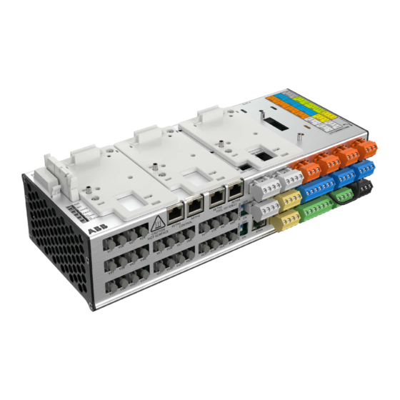
Page 11: Layout
Operation principle and hardware description 11 Layout The figures show the layout of the control unit. For the default I/O connection diagrams and more information on the connections, refer to the applicable hardware manual. Description I/O terminals SLOT 1 I/O extension, encoder interface or fieldbus adapter module connection. - Page 12 12 Operation principle and hardware description Description Analog input Analog output XCAN CAN bus XCAN TERM CAN bus termination switch Digital input XDIO Digital input/output XD2D Drive-to-drive link XD24 +24 V output (for digital input) XETH1 Ethernet ports for fieldbus, internal switch XETH2 XETH3 Ethernet ports for tool communication, internal...
- Page 13 Operation principle and hardware description 13 Description XFSO Not in use Environmental Humidity and temperature measurements sensors...
-
Page 15: Mechanical Installation
Mechanical installation 15 Mechanical installation Contents of this chapter This chapter describes the installation procedures and the contents of the delivery. Examining the delivery Make sure that these items are included: • control unit with the I/O connector plugs • UMU-01 memory unit •... -
Page 16: Installing The Control Unit On A Din Rail
The minimum recommended distance from such components is 200 mm (7.9 in). ABB recommends to install metallic screening between the control unit and the source of disturbance. This can reduce the required distance. - Page 17 Mechanical installation 17 Push the control unit to the DIN rail. It makes a click. To prevent the movement of the control unit, attach it to the DIN rail with end brackets (optional).
-
Page 18: Installing The Slot Adapter
18 Mechanical installation Installing the slot adapter WARNING! Obey the safety instructions of the drive. If you ignore them, injury or death, or damage to the equipment can occur. If you are not a qualified electrical professional, do not do installation, commissioning or maintenance work. -
Page 19: Electrical Installation
Electrical installation 19 Electrical installation Contents of this chapter This chapter describes the electrical installation of the control units. Installation procedure WARNING! Obey the safety instructions of the drive. If you ignore them, injury or death, or damage to the equipment can occur. If you are not a qualified electrical professional, do not do installation, commissioning or maintenance work. -
Page 21: Maintenance
Maintenance 21 Maintenance Contents of this chapter This chapter gives instructions on how to do maintenance on the control unit. -
Page 22: Replacing The Real-Time Clock Battery
22 Maintenance Replacing the real-time clock battery WARNING! Obey the safety instructions of the drive. If you ignore them, injury or death, or damage to the equipment can occur. If you are not a qualified electrical professional, do not do installation, commissioning or maintenance work. -
Page 23: Replacing The Memory Unit
Maintenance 23 Replacing the memory unit WARNING! Obey the safety instructions of the drive. If you ignore them, injury or death, or damage to the equipment can occur. If you are not a qualified electrical professional, do not do installation, commissioning or maintenance work. -
Page 24: Replacing The Microsdhc Memory Card
24 Maintenance Replacing the microSDHC memory card WARNING! Obey the safety instructions of the drive. If you ignore them, injury or death, or damage to the equipment can occur. If you are not a qualified electrical professional, do not do installation, commissioning or maintenance work. -
Page 25: Replacing The Control Unit
Tilt the control unit away from the DIN rail and lift it out. Make sure that the type of the new unit is correct. Type Can be replaced with UCU-22 UCU-22, UCU-23, UCU-24, UCU-25, UCU-26 UCU-23 UCU-23, UCU-24, UCU-25, UCU-26 UCU-24 UCU-24, UCU-25, UCU-26... -
Page 27: Technical Data
(22…12 AWG) Maximum tightening torque 0.45 N·m (4 lbf·in) 19…32 V DC, 2.9 A External power input. Two supplies can be connected to the UCU-22…26 for redundancy. Relay outputs RO1…RO4 Connector pitch 5 mm, wire size 0.5 … 2.5 mm (22…12 AWG) - Page 28 28 Technical data Digital inputs/outputs DIO1 and DIO2 Connector pitch 5 mm, wire size 0.5 … 2.5 mm (22…12 AWG) (XDIO:1 and XDIO:2) Maximum tightening torque 0.45 N·m (4 lbf·in) Input/output mode selection by As inputs: 24 V logic levels: "0" < 5 V, "1" > 15 V. R : 2.0 kohm.
- Page 29 Technical data 29 CAN connection (XCAN) Connector pitch 5 mm, wire size 0.5 … 2.5 mm (22…12 AWG) Maximum tightening torque 0.45 N·m (4 lbf·in) Termination by switch (XCAN TERM) Safe torque off connection (XSTO) Connector pitch 5 mm, wire size 0.5 … 2.5 mm (22…12 AWG) Maximum tightening torque 0.45 N·m (4 lbf·in) Input voltage range: -3…30 V DC...
-
Page 30: Ucu-22
30 Technical data UCU-22…26 ground isolation diagram ■ XPOW XD2D X485 XCAN XETH1 XETH2 XETH3 XETH4 XPAN XRO1-XRO4 COM1 … COM4 XD24 +24VD DICOM +24VD DIOGND XDIO DIO1 DIO2 DIOGND DIOGND DIIL XSTO XSTO OUT Power supply ground *The maximum common mode voltage between each AI input and AGND is ±30 V... -
Page 31: Additional Information On The Connections
Use shielded twisted-pair cable with a twisted pair for data and a wire or another pair for signal ground (nominal impedance 100…165 ohm, for example Belden 9842) for the wiring. For best immunity, ABB recommends high quality cable. Keep the cable as short as possible. Avoid unnecessary loops and parallel runs near power cables such... -
Page 32: The X485 Connector
The control unit has an on-board data logger that collects real-time data from the power modules to help fault tracing and analysis. The data is stored onto the microSDHC memory card inserted into the UMU memory unit and can be analyzed by ABB service personnel. -
Page 33: Other Information
Technical data 33 Other information Weight 1.70 kg (3.75 lb) Protection classes Degree of protection IP20 (IEC/EN 60529) Enclosure type (UL 508C) UL Open Type Overvoltage category (IEC 60664-1) Protective class (IEC/EN 61800-5-1) Protective class (IEC 62109-1) Ambient conditions Air temperature in opera- -10…70 °C (14…158 °F) tion Storage and transportation conditions... -
Page 34: Cyber Security Disclaimer
ABB and its affiliates are not liable for damages and/or losses related to such security breaches, any unauthorized access, interference, intrusion, leakage and/or theft of... - Page 35 Dimension drawings 35 Dimension drawings Contents of this chapter This chapter shows the dimensions of the control unit.
- Page 36 36 Dimension drawings Dimension drawings of the control unit...
- Page 37 Product and service inquiries Address any inquiries about the product to your local ABB representative, quoting the type designation and serial number of the unit in question. A listing of ABB sales, support and service contacts can be found by navigating to www.abb.com/searchchannels.
- Page 38 3AXD50000817726A © Copyright 2023 ABB. All rights reserved. Specifications subject to change without notice.