Advertisement
Quick Links
Field Intelligent Device Series
Electromagnetic Flowmeter
Introduction
The electromagnetic flowmeter uses Faraday's Law of
electromagnetic induction to measure the process flow.
The device consists of two units: a detector, through
which the fluid to be measured flows and in which
low-level signals proportional to flow rates are obtained;
and a converter, which supplies excitation current to the
detector, and amplifies the signals from the detector and
then processes and converts the signals into the 4–20
mA dc current signal. The LF470 is a small meter size
detector designed to measure a small amount of fluids
containing substances such as chemicals.
The wetted materials for the LF470 are corrosion
resistant ceramic and platinum electrodes and are
applicable to almost any kind of fluids. The LF470 is a
lightweight
palm-sized
multi-functional converter LF622 (separate type) and
1
LF232*
(separate type) equipped with its patented
Noise-Sentry original noise-suppression circuit and
advanced algorithms. The LF470 is highly resistant to
noise and provides a stable output even for fluids
containing slurries. IR (Infrared) switches enable
parameter setting of the converter without removing the
cover. Flow direction can be set in either way, and its
unique 128 x 128 dot matrix LCD display allows the
LCD to be rotated electronically to be rotated to 90, 180
and 270 degrees without opening the cover
*1: Please refer to the document "TIC-LF232".
*2: HART protocol (Highway Addressable Remote
Transducer) is a communication protocol for industrial
sensors recommended by the HCF (HART Communication
Foundation).
** DevComm2000 Smart Device Communicator available
through TIC for performing HART device configurations on PC
or laptop.
*3: PROFIBUS is the communication protocol for factory
and process automation that the PROFIBUS Organization
recommends. Instead of analog control with a
conventional analog signal (4-20mA), it is the fieldbus
which digitizes all signals. Flowmeters support
PROFIBUS-PA.
*4: Modbus is the communication protocol that Modicon Inc.
developed. Physical layer is RS485.
*
Modbus is the communication protocol that Modicon Inc.
developed. Physical layer is RS485.
Fluid to be
measured
Signal cable
Excitation cable
LF470
Detector
Figure 1. Configuration Diagram
detector.
Combined
with
Power supply
4-20mA dc output
and pulse output
LF622 or LF232
Converter
1/10",1/6",1/4" (2.5,4,6mm )
LF470
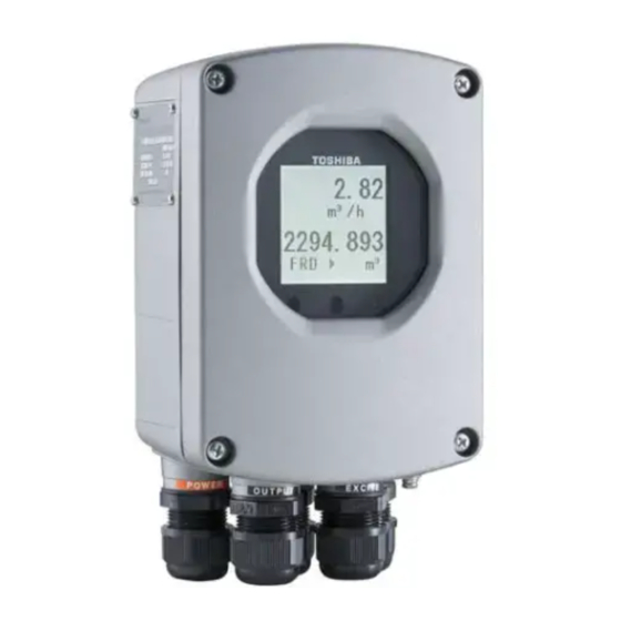
Figure 2. Electromagnetic Flowmeter
LF470/LF622
Certification number
Specifications
Overall Specifications
Measurement range in terms of flow velocity:
0–1.0ft/s to 0–32.8ft/s (0–0.3 m/s to 0–10 m/s )
Accuracy: The overall accuracy combined with the
LF622 or LF232 converter is shown in the
following table.
Flow rate as a
percent of range
1.0-3.3ft/s
(0.3-1.0m/s )
±0.8% of FS
50~100%
±0.8% of FS
0~50%
Note: The accuracy is measured under standard
operating conditions at Toshiba's calibration facility.
Fluid conductivity: 50µS/cm minimum
Fluid temperature:
Pipe connection material
Stainless steel and other metals
Polyvinyl chloride
(shock-resistant)
Ambient temperature: 14 to 140 °F (–10 to +60 °C )
Structure: IP67
Power consumption:
・When combined with the LF622 converter:
Standard:10W(14VA)
at AC100V and Excitation current:0.2A
MAX:15W (22VA)
MAX:17W(24VA) with PROFIBUS
LF470/LF622
LF622
Z01207
Accuracy
3.3-32.8ft/s
(1.0-10m/s )
±0.8% of rate
±0.4% of FS
Fluid temperature
14 to 248 °F
(-10℃~+120℃)
14 to 140 °F
(-10℃~+60℃)
TIC-LF470H
Advertisement

Related Manuals for Toshiba LF470


Summary of Contents for Toshiba LF470
- Page 1 4–20 mA dc current signal. The LF470 is a small meter size detector designed to measure a small amount of fluids LF622 LF470 containing substances such as chemicals.
- Page 2 Output signals Approximately 14W (25VA) Current output: Model LF470 Detectors 4–20mAdc (load resistance 0 to 750) Fluid pressure: - 15 to 150 psi, or - 1.0 to 10 bar Note: The current output cannot be used with the (-0.1 to 1 MPa) PROFIBUS-PA communication.
- Page 3 Zero span calibration tool allows unit to be See Figure 5 re-calibrated and verified using an internal software MTBF: program. (For more information contact Toshiba Converter: 220,000 hours (25 years) at 77 °F (25 °C) International Corp.) based on strict military specification MIL-HDBK-217F Detector: 350,000 hours (40 years) at 77 °F (25 °C)
-
Page 4: Installation
Th is le n g th b ec o me s 78 m m if th e pip e If a mounting plate is needed for the LF470, fix the plate (a) c o nn e c tio n p o r t t hr e ad is Rc ( PT) 1/ 2 above to the bottom of the LF470. -
Page 5: Profibus-Pa
Signal common for DI and DO Digital output 1 Grounding with 100Ω or less Power cable Connected detector I/O cable ground resistance Figure 6. Separate type LF470/LF622 flowmeters wiring Diagram Table 1. LF622 Converters Signal Table Symbol Description Cable L1 (+) Power supply Power cable L2 (-) -
Page 6: Ordering Information
(3) The fluid to be measured must be held still in the In areas like the following, there may be the case that pipe when the LF470 is being adjusted. If the fluid infrared switches do not function correctly. (If these are can not be stopped after the LF470 installation, unavoidable, use an appropriate cover.) - Page 7 TIC-LF470H Table 4. Specification Code ( LF470 Detector ) Model Specification Code Description 1 2 3 4 5 6 7 8 9 10 11 12 13 14 L F 4 7 0 LF470 Flowmeter Meter size 1/10" (2.5 mm ) 1/6"...
- Page 8 Specifications are subject to change without notice. Printed in Japan 2011-6 (TDOC) Misuse of this product can result in damage to property or human injury. © TOSHIBA Corporation 2011 Read related manuals carefully before using this product. All Rights Reserved.