Advertisement
Quick Links
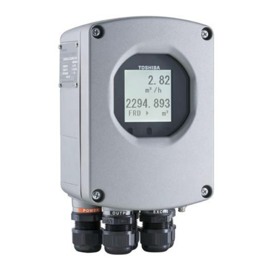
Field Intelligent Device – Mount-Anywhere Series - Wafer
Electromagnetic Flowmeter
Introduction
The electromagnetic flowmeter uses Faraday's Law of
electromagnetic induction to measure the process flow.
The device consists of two units: a detector, through
which the fluid to be measured flows and in which
low-level signals proportional to flow rates are
obtained; and a converter, which supplies excitation
current to the detector, and amplifies the signals from
the detector and then processes and converts the signals
into the 4–20mAdc current signal or communication
signal. The meter features a Mount- Anywhere
magnetic field distribution technology, the meter is
highly immune to upstream flow disturbances.
Combined with a multi-functional converter LF620
(combined type) or LF622 (separate type) equipped
with its patented Noise-Sentry original noise-
suppression circuit and advanced algorithms. The
LF410 has a very high tolerance to noise, giving the
unit a very stable output even for slurry fluid
measurement. IR (Infrared) switches enable parameter
setting of the converter without removing the cover.
Flow direction can be set in either way, and its unique
128 x 128 dot matrix LCD display allows the LCD to
be rotated electronically to 90, 180 and 270 degrees
without opening the cover.
*1: HART protocol (Highway Addressable Remote
Transducer) is a communication protocol for industrial
sensors recommended by the HCF (HART
Communication Foundation).
** DevComm2000 Smart Device Communicator available for
performing HART device configurations on PC or laptop is
available through the supplier .
*2: PROFIBUS is the communication protocol for factory
and process automation that the PROFIBUS
Organization recommends. Instead of analog control
with a conventional analog signal (4-20mA), it is
fieldbus which digitizes all signals. Flowmeters support
PROFIBUS-PA.
*
Modbus is the communication protocol that Modicon Inc.
developed. Physical layer is RS485.
Converter
I/O
Terminal box
Power
Detector
supply
Combined type
LF410/LF620
LF414/LF620F
Figure1. Configuration
Converter
Signal cable
Power
supply
I/O
Detector
Separate type
LF410/LF622
LF414/LF622F
1/2" to 4" (15 to 100 mm)
LF410/LF620
LF414/LF620F
Figure2. LF410 Mount-Anywhere series
Flowmeters
Specifications
Overall Specifications
Measurement range in terms of flow velocity:
1.0 ft/s to 32.8 ft/s (0.3 m/s to 10 m/s).
0.3 ft/s to 1.0 ft/s (0.1 m/s to 0.3 m/s)
range is available optionally.
± ± ± ± 0.2 % of Rate
Accuracy:
* This pulse output error result is established under standard
operating conditions at Toshiba's flow calibration facility,
Fuchu Japan. (NIST Traceable).
* Individual meter measurement error may vary up to ±0.5% of
Rate at 1.64ft/s (0.5m/s) or more and ±0.3% of rate ±0.039
inch/s (1mm/s) at 1.64 ft/s (0.5 m/s) or less.
* Current output: plus ± 8µA (0.05% of span.)
* Refer to individual calibration data for each individual meter's
measurement error.
Fluid conductivity: 5µS/cm minimum
Fluid temperature:
14 to 356 °F (–10 to +180°C):Separate type for
ceramic tube.
14 to 248°F (–10 to +120°C): Combine type for
ceramic tube
Ambient temperature: - 4 to 140 °F ( - 20 to + 60 °C)
LF410 /LF620
LF410 /LF622
LF410
LF622
LF414
LF622F
Certification number
Z01207
*
EJL-136F
Advertisement

Related Manuals for Toshiba LF410


Summary of Contents for Toshiba LF410
- Page 1 (combined type) or LF622 (separate type) equipped with its patented Noise-Sentry original noise- suppression circuit and advanced algorithms. The LF410 has a very high tolerance to noise, giving the unit a very stable output even for slurry fluid measurement. IR (Infrared) switches enable parameter setting of the converter without removing the cover.
- Page 2 Note: See Table 5 for optional materials and other Class I, II, III, Division 2, Groups A-G related information. Detector and converter combination: LF410/LF620: Combined type for standard Coating — specification. 1” to 4” (25 to 100mm): LF410/LF622: Separate type for standard No coating (stainless steel body).
- Page 3 EJL-136F Note: The same and simultaneous pulse is not available between DO1 and DO2.) Model LF620 and LF622 converters • Multi-range selection outputs (Note 1) Input signals • High, High high, Low, and/or Low low alarm Analog signal — the voltage signal from detector, outputs (Note 2) proportional to process flow rate (for LF622 •...
- Page 4 See Figure 9 (for Separate type) software program (For more information contact MTBF: Toshiba International Corp.) Converter: 220,000 hours (25 years) at 77 °F (25 °C) Conditions when power fails: based on strict military specification Parameter setting values are stored in non–volatile...
-
Page 5: Installation
9 3.15 8.90 2.60 approx. 9 Note: 1 inch = 25.4mm Figure 3. LF410/LF620 and LF414/LF620F flowmeters Figure 4. LF410/LF620 and LF414/LF620F Meter size 1/2"(15mm) flowmeters Meter size 1"(25mm) The dimension of L1 changes when Pt-Ir or Ta material is chosen from the grounding ring. - Page 6 Pt-Ir or Ta Meter size 1/2”(15mm) 3.03 inch(77mm) 1”(25mm) 3.74 inch(95mm) 1 1/2”(40mm) 4.53 inch(115mm) 2”(50mm) 4.96 inch(126mm) Note1: 1 inch = 25.4mm 3”(80mm) 4.96 inch(126mm) 4”(100mm) 5.35 inch(136mm) Figure 5. LF410/LF620 and LF414/LF620F flowmeters Meter sizes 1 1/2"(40mm) to 4"(100mm)
- Page 7 Note1: Cable glands are not provided for LF414 of FM and 3”(80mm) 4.96 inch(126mm) CSA approved type. 4”(100mm) 5.35 inch(136mm) Refer to the part of Cable connection port at detector. Note2: 1 inch = 25.4mm Figure 6. Separate type detectors LF410/LF414 Meter sizes 1/2" (15mm)
- Page 8 1 1/2”(40mm) 4.53 inch(115mm) CSA approved type. 2”(50mm) 4.96 inch(126mm) Refer to the part Cable connection port at detector. 3”(80mm) 4.96 inch(126mm) Note2: 1 inch = 25.4mm 4”(100mm) 5.35 inch(136mm) Figure 7. Separate type detectors LF410/LF414 Meter sizes 1" (25mm)
- Page 9 4.53 inch(115mm) CSA approved type. 2”(50mm) 4.96 inch(126mm) Refer to the part of Cable connection port at 3”(80mm) 4.96 inch(126mm) detector. 4”(100mm) 5.35 inch(136mm) Note2: 1 inch = 25.4mm Figure 8. Separate type detectors LF410/LF414 Meter sizes 1 1/2"(40mm) to 4"(100mm)
- Page 10 *1 Locate an external double-pole power switch on the power line near the flowmeter within easy reach of operation. Use the appropriate switch rating as shown below: Switch rating: 250Vac, 6A or more In rush current: 15A or more Figure 10. Combined type LF410/LF620 and LF414/LF620F flowmeters Wiring Diagram...
-
Page 11: Profibus-Pa
Digital output 1 Grounding with 100Ω or less Power cable Connected detector I/O cable ground resistance Figure 11. Separate type LF410/LF622 and LF414/LF622F flowmeters wiring Diagram Table 2. LF620, LF620F, LF622 and LF622F Converters Signal Table Symbol Description Cable L1 (+) - Page 12 EJL-136F (7) Only one PROFIBUS-PA cable goes through a Wiring Precautions cable gland of the Electromagnetic Flowmeter. (1) Explosion proof type flowmeters are not provided Please use the junction box at system cable glands. configuration Refer to the part Cable connection port at detector (8) Install a terminator to flowmeter that connected and converter.
- Page 13 (2) Where smoke and steam may occur. (3) Where exposed to direct snow, ice or mud. Ordering Information 1. When ordering the LF410 series flowmeters, refer to Tables 5 and 6 (Type Specification Codes). An entry must be made for each of the columns in each of these tables.
- Page 14 Note5: Phthalic acid resin coating is standard for the flowmeter with meter size 1/2”(15mm). Note6: Consult Toshiba before ordering when choose materials at the wetting parts. Note7: Check the Table 1 whether your chosen meter size meets this directive or not when the meter is shipped to EU. If yes, need to choose this code.
- Page 15 Specifications are subject to change without notice. Printed in Japan 2017-7 (TBLS) Misuse of this product can result in damages to property or human injury. ©Toshiba Infrastructure Systems & Solutions Corporation Read related manuals carefully before using this product. 2017...