Table of Contents
Advertisement
Field Intelligent Device Series
Sanitary Electromagnetic Flowmeter
Introduction
Sanitary electromagnetic flowmeters LF490 series are
designed for applications handling food and beverages.
Sanitary flowmeters must be structured in such a way
that operation and handling is simple, easy and
thorough for the purpose of sanitary control such as
cleaning (CIP/SIP), sterilization and drying. The
sanitary flowmeter has features provided with normal
electromagnetic flowmeters and by using sanitary
fittings for pipeline connections fluid does not remain
in any place along the detector pipeline. Therefore, it is
fit for flowrate measurement for food and beverages.
The electromagnetic flowmeter uses Faraday's Law of
electromagnetic induction to measure the process flow.
The device consists of two units: a detector, through
which the fluid to be measured flows and in which
low-level signals proportional to flow rates are
obtained; and a converter, which supplies excitation
current to the detector, and amplifies the signals from
the detector and then processes and converts the
signals into the 4–20mAdc current signal or
communication signal. With the unique patented
Mount-Anywhere magnetic field distribution
technology, the meter is highly immune to upstream
flow disturbances. Combined with a multi-functional
converter LF610 (combined type) or LF612 (separate
type) equipped with its patented Noise-Sentry original
noise-suppression circuit and advanced algorithms.
The LF490 has a very high tolerance to noise, giving
the unit a very stable output even for slurry fluid
measurement. IR (Infrared) switches enable parameter
setting of the converter without removing the cover.
Flow direction can be set in either way, and its unique
128 x 128 dot matrix LCD display allows the LCD to
be rotated electronically to 90, 180 and 270 degrees
without opening the cover.
Converter
I/O
Power supply
Detector
Combined type
LF490/LF610
LF494/LF610F
Figure1. Configuration
Converter
Signal cable
Terminal box
Excitation cable
Detector
Separate type
LF490/LF612
LF494/LF612F
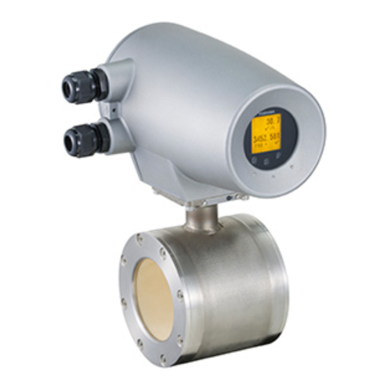
LF490/LF610
LF494/LF610F
Figure2. LF490 series flowmeters
The AF900 hand-held terminal (HART*
communicator) can be used to communicate with the
flowmeter from a remote place. PROFIBUS-PA*
interface is available as an option.
*1: HART protocol (Highway Addressable Remote
Transducer) is a communication protocol for industrial
sensors recommended by the HCF (HART
Communication Foundation).
*2: PROFIBUS is the communication protocol for factory
and process automation that the PROFIBUS
Organization recommends. Instead of analog control
with a conventional analog signal (4-20mA), it is the
fieldbus which digitizes all signals. Flowmeters support
PROFIBUS-PA.
Power
supply
I/O
LF494/LF610
LF494/LF612
1S to 4S (25 to 100 mm)
LF490
LF612
LF494
LF612F
Certification
number
Z01207
1
TIC-LF494B
2
Advertisement
Table of Contents

Related Manuals for Toshiba Sanitary Electromagnetic Flowmeter TIC-LF494B


Summary of Contents for Toshiba Sanitary Electromagnetic Flowmeter TIC-LF494B
- Page 1 Field Intelligent Device Series Sanitary Electromagnetic Flowmeter Introduction Sanitary electromagnetic flowmeters LF490 series are designed for applications handling food and beverages. Sanitary flowmeters must be structured in such a way that operation and handling is simple, easy and thorough for the purpose of sanitary control such as cleaning (CIP/SIP), sterilization and drying.
-
Page 2: Specifications
±0.2 % of Rate Accuracy: * This pulse output error result is established under standard operating conditions at Toshiba's flow calibration facility, Fuchu Japan. (NIST Traceable). * Individual meter measurement error may vary up to ±0.5% of Rate at 1.64 ft/s (0.5m/s) or more and ±0.3% of rate ±0.039 inch/s (1mm/s) at 1.64ft/s (0.5 m/s) or less. -
Page 3: Communications Output
Zero span calibration tool allows unit to be re-calibrated and verified using an internal software program. (For more information contact Toshiba International Corp.) Conditions when power fails: Parameter setting values are stored in non-volatile memory and the values will be restored when the power returns to normal condition. -
Page 4: Surge Protection
• Digital output: OFF • LCD display: No display • PROFIBUS: No communication Power supply: One of the following can be selected: • 100 to 240Vac, 50/60Hz (std.) (allowable voltage 80 to 264Vac) • 24Vdc (allowable voltage 18 to 36Vdc) •... -
Page 5: Installation
Installation Dimensions (Combined type) Clamp connection 8.86(225) 1.42(36) 5.16(131) Note1: Clamp (Joint) size is different from meter size of LF490 and LF494. See the following table. Note2: Cable glands are not provided for cFMus approved type. For English unit Meter size Joint size (inch) (ISO2852) - Page 6 Dimensions (Separate type) Clamp connection 3.46(88) 1.57(40) 1.38(36) R(PT)1/2 Male screw (L2) ΦD1 Clamp (Joint) size is different from meter size Note1: of LF490. See the following table. Cable glands are not provided for cFMus Note2: approved type. For English unit Meter size Joint size (inch)
- Page 7 101.6 2.85 119.0 72.3 76.3 100 (4S) 5 1/2S 101.6 5.6 155.0 97.6 101.6 Note1: This special Ferrule, which fits on TOSHIBA LF490 and LF494, can be fastened to ISO2852 clamp. Tri-clamp® is available to use the same joint size instead of ISO2852 clamp except meter size 4"...
-
Page 8: External Connections
4 – φ0.43(φ11) 4-φ 11 5.94(151) Attachment 取付金具 2.91(74) LCD display 74 ±0.3 LCD 表示器 IR Switch 赤外線スイッチ Cable ground ケーブルグランド 矢視A Figure 8. Separate type converter LF612 and LF612F External Connections Combined type LF490/LF610 and LF494/LF610F flowmeters Ground terminal Intermediate voltage (IV) wire, 5.5mm... - Page 9 Separate type LF490/LF612 and LF494/LF612F flowmeters Terminal board Thick walled steel conduit Signal cable (2-wire shielded hard-rubber sheathed cable) Connected detector Excitation cable (3-wire shielded hard-rubber cable) Figure 10. Separate type LF490/LF612 and LF494/LF612F flowmeters wiring Diagram Table 1. LF610, LF610F, LF612 and LF612F Converters Signal Table Symbol L1 (+) L2 (-)
-
Page 10: Wiring Precautions
Wiring Precautions (1) Explosion proof type flowmeters are not provided cable glands. Refer to the part Cable connection port at detector and converter. (2) Connect the grounding wire (IV wire 5.5mm² or more) to a good earth ground (100 Ω or less ground resistance). -
Page 11: Ordering Information
4. I/O function setting 5. Ordering scope: Flow calibration data: (required or not) 6. Other items Specifications other than standard items Consult a Toshiba representative before ordering when choosing materials of the wetted parts such as lining, electrodes, and grounding rings. - Page 12 Note2: Tri-clamp® is available to use the same joint size instead of ISO2852 clamp except meter size 100mm (4"). Note3: Toshiba’s original ferrule is required to use for LF490 series detectors to keep just fitting between the joint in case of choosing clamp type.
- Page 13 Table 6. Specification Code for converters Model Specification Code 1 2 3 4 5 6 7 8 9 10 11 12 13 14 L F 6 1 Code explanation: : Standard Table 7. Type Specification Code for Maintenance Parts Meter size Joint size inch(mm) (ISO2852)
- Page 14 TIC-LF494B This Page Intentionally Blank...
- Page 15 TIC-LF494B This Page Intentionally Blank...
- Page 16 Specifications are subject to change without notice. Misuse of this product can result in damages to property or human injury. Printed in Japan 2008-5 (TDOC) Read related manuals carefully before using this product. © TOSHIBA Corporation 2008 All Rights Reserved. http://www.toshiba.com/ind/ TIC-LF494B...