Advertisement
Quick Links
M.A. Selmon Company, Inc
203-377-3525
4 Oxford Rd.
Milford, CT 06460
Introduction
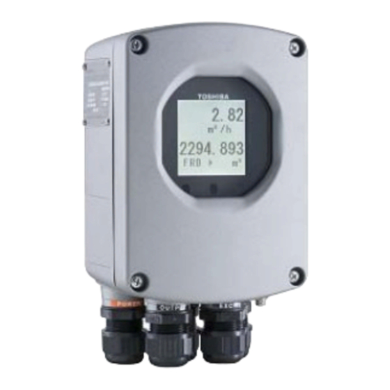
Combined with a multi-functional converter LF620
(combined type) or LF622 (separate type) equipped
with its original noise-suppression circuit and
advanced algorithms. IR (Infrared) switches enable
parameter setting of the converter without removing
the cover. Flow direction can be set in either way, and
its 128 x 128 dot matrix LCD display allows the LCD
to be rotated electronically to 90, 180 and 270 degrees
without opening the cover. The terminal block in LCD
side make easy to wire in case of the combined type.
*1: HART protocol (Highway Addressable Remote Transducer) is a
communication protocol for industrial sensors recommended by the
HCF (HART Communication Foundation).
** DevComm2000 Smart Device Communicator available
through TIC for performing HART device configurations on
PC or laptop .
*2: PROFIBUS is the communication protocol for factory automation and
process automation that the PROFIBUS Organization recommends.
Instead of analog control with a conventional analog signal (4-20mA),
it is one kind of the fieldbus which digitizes all signals. Flowmeters
support PROFIBUS-PA.
*3: Modbus is the communication protocol that Modicon Inc. developed.
Physical layer is RS485.
Figure1. LF620 series Flowmeter Converters
Field Intelligent Device Series
Electromagnetic Flowmeter Converter
LF620
LF622
LF620F
LF622F
Certification number
Z01207
Specifications
Model LF620 and LF622 converters
Input signals
Analog signal — the voltage signal from detector,
proportional to process flow rate (For LF622
separate type converter).
Digital input DI
Signal type: 20 to 30Vdc voltage signal
Input resistance: 2.7k
Number of inputs: one point
Note: DI cannot be used with the Modbus
communication.
DI function — One of the following functions can
be assigned to the optional DI signal.
Range switching — Selects either the higher or
lower range in the unidirectional or
bidirectional 2-range setting.
Totalizer control — Starts and stops the built-in
totalizer.
Fixed-value outputs — Outputs fixed-values for
current and pulse outputs.
Zero adjustment — Executes zero adjustment
(on-stream at zero flow rate).
Output signals
Current output:
4–20mAdc (load resistance 0 to 750)
Note: The current output cannot be used with
the PROFIBUS-PA communication.
Digital outputs — Two points are available as
follows.
Digital output DO1 :
Output type: Transistor open collector
Number of outputs: One point
Output capacity: 30Vdc, 200mA maximum
Note: DO1 cannot be used if Modbus
communication connection is 3 lines.
Digital output DO2 :
Output type: Solidstate relay output (non
polarity)
Number of outputs: One point
Output capacity: 150Vdc, 150mA maximum
or 150 V ac (peak to peak), 100mA maximum
Note: DO2 cannot be used with the Modbus
communication.
LF620,LF622
TIC-LF620E
Advertisement

Related Manuals for Toshiba LF620


Summary of Contents for Toshiba LF620
- Page 1 Field Intelligent Device Series LF620,LF622 Electromagnetic Flowmeter Converter Introduction Specifications Combined with a multi-functional converter LF620 Model LF620 and LF622 converters (combined type) or LF622 (separate type) equipped Input signals with its original noise-suppression circuit and advanced algorithms. IR (Infrared) switches enable Analog signal —...
- Page 2 Function blocks : AI(Flow)×1 , Totalizer×1 • Modbus(opt.) Cable connection ports: Physical layer : RS485 Cable glands — Protocol : Modbus LF620 and LF622 without cFMus Approval: Mode : RTU Provided as standard OD of cableφ11~13mm Baudrate : 4800, 9600, 19200bps Material Nylon 66 Data length : 8bit G (PF) 1/2 male threads..
- Page 3 TIC-LF620E Applicable diameter — 11 to 13mm (0.433 to 0.512 inch) Vibration resistance: No resonance to the following levels of vibration: • 10 to 150Hz with acceleration of 9.8m/s • Vibration of 30Hz with 29.4 m/s in 4h in each direction will not cause any defect to unit.
-
Page 4: Installation
TIC-LF620E Installation Dimension Attachment LCD display I/O cable ground Excitation cable ground Plate Power supply Signal cable ground cable ground Option cable ground IR Switch Note: Cable glands are not provided for LF622F cFMus approved type. Refer to the part Cable connection port at detector. Figure 2. - Page 5 *1 Locate an external double-pole power switch on the power line near the flowmeter within easy reach of operation. Use the appropriate switch rating as shown below: Switch rating: 250Vac, 6A or more In rush current: 15A or more Figure 3. Combined type LF620 and LF620F converters Wiring Diagram...
-
Page 6: Profibus-Pa
TIC-LF620E Instrument panel : Ordered separately Grounding with 100Ω or less Ⅳ wire 5.5mm or more ground resistance Power switch Grounding with 100Ω or less (External double-pole power switch) ground resistance Power supply Thick walled steel conduit Current output (4~20mAdc) Signal cable or PROFIBUS (2-wire shielded hard-rubber sheathed cable) -
Page 7: Wiring Precautions
An independent earth ground is recommended. (2) The allowable cable lengths between Toshiba detector and Toshiba converter for the separate type flowmeter depend on the electrical conductivity of the object fluid. Refer to each specification sheet. - Page 8 Specifications are subject to change without notice. Printed in Japan 2011-6 (TDOC) Misuse of this product can result in damages to property or human injury. © TOSHIBA Corporation 2011 Read related manuals carefully before using this product. All Rights Reserved.