
Related Manuals for Erbe VIO 300 S


Summary of Contents for Erbe VIO 300 S
- Page 1 SERVICE MANUAL 300 S 200 S ® ® V 2.0.x V 2.0.x ELECTROSURGERY 80116-918 10.15...
- Page 3 SERVICE MANUAL 300 S ® 200 S ®...
- Page 4 (by photocopying, microfilming or other methods) or processed, duplicated or dissem- inated by the use of electronic systems without the written consent of Erbe Elektromedizin GmbH. The information contained in this manual may be amended or supplemented without prior notice and represents no obli- gation on the part of Erbe Elektromedizin GmbH.
-
Page 5: Table Of Contents
Table of Contents Table of Contents Safety information ........7 Classification of the safety information. - Page 6 Table of Contents Maintenance and servicing ....... . 39 Who is allowed to perform servicing and maintenance work? ... . . 39 What is a technical safety check?.
-
Page 7: Safety Information
The supply voltage must match the voltage specified on the rating plate. Connect the unit / the equipment cart to a properly installed grounded outlet. Only use the Erbe power cord or an equivalent power cord for this purpose. The power cord must bear the national test sym- bol. -
Page 8: Electrostatically Sensitive Components
Liability and warranty ATTENTION! Adjustments, tests, modifications, maintenance and repair work may only be performed by Erbe or persons trained by Erbe. If the work is not performed by trained persons, Erbe accepts no liability and warranty rights become void. -
Page 9: Unit Description
In the VIO 300 S the unit variant 1 (= basic variant) contains all modes ap- proved for this unit. These modes are described in the User Manual of the unit. All other unit variants contain less modes than the basic variant. A list of all unit variants for the VIO 300 S can be requested from Erbe Tübingen. -
Page 10: Controls At The Front
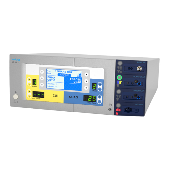
This chapter contains an overview of the controls of the unit(s). The rel- evant User Manual for the unit(s), knowledge of which is assumed for servicing work, provides detailed information about how to use the unit(s). VIO 300 S 300 S FORCED COAG... -
Page 11: Controls At The Rear
2 • Unit description Controls at the rear Fig. 2-2 Footswitch sockets ECB socket (Erbe Communication Bus) Potential equalization terminal Power supply module with fuses / 64... - Page 12 2 • Unit description / 64...
-
Page 13: Technical Data
3 • Technical Data CHAPTER 3 Technical Data Power connection Rated supply voltage 100 V – 120 V ± 10 % 220 V – 240 V ± 10 % Rated supply frequency 50 / 60 Hz 50 / 60 Hz Line current Power input in standby mode 40 watts... - Page 14 3 • Technical Data Acclimatizing If the unit has been stored or transported at temperatures below +10 °C or above +40 °C, the unit will require approx. 3 hours to acclimatize at room temperature. Standards Classification according to EC Directive 93/42/EEC II b Protection class as per EN 60 601-1 Type as per EN 60 601-1...
-
Page 15: Setup And Service Settings
4 • Setup and Service settings CHAPTER 4 Setup and Service settings General information This unit features two levels for changing settings: • Setup level • Service level Overview of Setup settings Accessible to users and service personnel. Setting Available from Description Contrast V 2.0.x... -
Page 16: Overview Of Service Settings
4 • Setup and Service settings Overview of Service settings Only accessible for service personnel. Password-protected. IMPORTANT! The service menu is only available in English depending on the lan- guage setting selected on the unit. Setting Available from Description Date V 2.0.x Self-explanatory. -
Page 17: Call Up Setup And Service Settings
4 • Setup and Service settings Setting Available from Description IES parameter V 2.0.x Setting the parameters for operation of the IES 2 smoke evacu- ation system. EIP parameter V 2.0.x Setting the parameters for operation of the EIP 2 irrigation pump. - Page 18 4 • Setup and Service settings Call up Service level 1. Call up "CUT-COAG" box and select menu item "Prog.Setup". 2. Select menu item "Service". The unit switches to the "Password input" box. 3. In the menu item "Case" select upper case. 4.
-
Page 19: Change Settings
4 • Setup and Service settings 7. Confirm password with menu item "SERVICE". The unit switches to the Service level. For the settings that can be changed there see table page 16. IMPORTANT! Once the keyword has been entered and provided the unit remains switched on, the Service level can be called up direct, i.e. - Page 20 4 • Setup and Service settings / 64...
-
Page 21: Remedying Malfunctions
Safety information ATTENTION! Adjustments, technical tests, modifications, maintenance and repair work may only be performed by Erbe or persons trained by Erbe. If the work is not performed by trained persons, Erbe accepts no liability and warranty rights become void. -
Page 22: A/E-Errors
Description Action nizing code mation module Restart the unit. If the error occurs again, notify Erbe Ser- vice. 02 – 04 Restart the unit. If the error occurs again, notify Erbe Ser- vice. Button error receptacle 1. Check the keyboard. - Page 23 21 – 23 Restart the unit. If the error occurs again, notify Erbe Ser- vice. Restart the unit. If the error occurs again, notify Erbe Ser- vice. Type detection of receptacle 1 Check and save the recepta- fails to agree with the stored cle configuration in the "Ver-...
- Page 24 Description Action nizing code mation module 7D + 7E Restart the unit. If the error occurs again, notify Erbe Ser- vice. Operating system error. Information, no fault condi- tion. Internal state incorrect. Information, no fault condi- tion. 81 – 83 Protocol violation CAN.
-
Page 25: B-Errors
02 + 03 Restart the unit. If the error occurs again, notify Erbe Ser- vice. NESSY message. NE is not Check the NE accessories and correctly applied: NE setting in setup. Occurs if measurement of the... - Page 26 Occurs if an error is signaled by the Nessy symmetry mon- itoring during activation. 2A – 2C Restart the unit. If the error occurs again, notify Erbe Ser- vice. 50 – 59 Restart the unit. If the error occurs again, notify Erbe Ser- vice.
- Page 27 Occurs if a footswitch is dis- connected from the system. Restart the unit. If the error occurs again, notify Erbe Ser- vice. Restart the unit. If the error occurs again, notify Erbe Ser- vice. No status message from APC Check connectors.
- Page 28 Activation is only possible Check the accessories. If the with a valid instrument: error persists, notify Erbe Occurs if a MF receptacle is Service. activated at which no instru- ment is recognized.
- Page 29 Occurs if the EIP module is disconnected from the sys- tem. D4 – D6 Restart the unit. If the error occurs again, notify Erbe Ser- vice. Occurs if a module responds Remove the module con- that is not supported by the cerned from the unit and system.
-
Page 30: C-Errors
Description Action nizing code mation module Restart the unit. If the error occurs again, notify Erbe Ser- vice. 04 – 06 Restart the unit. If the error occurs again, notify Erbe Ser- vice. Restart the unit. If the error occurs again, notify Erbe Ser- vice. - Page 31 Action nizing code mation module 7D – 7F Restart the unit. If the error occurs again, notify Erbe Ser- vice. 81 – 84 Restart the unit. If the error occurs again, notify Erbe Ser- vice. 91 + 92 Restart the unit. If the error occurs again, notify Erbe Ser- vice.
-
Page 32: D-Errors
ECB fault. Restart the unit. If the error occurs again, notify Erbe Ser- vice. The VIO first receives a one- Information, no fault condi- second signal from the IES 2 tion. and then from the VIO master Change the activation unit. -
Page 33: Err-Errors
Err = Error display on the seven-segment displays Display Description Action ErrdIS Restart the unit. If the error occurs again, notify Erbe Service. ErrtAS Restart the unit. If the error occurs again, notify Erbe Service. F-Errors Recognizing module: F = Footswitch... -
Page 34: 2,3,5,6-Errors
2,3,5,6 01 – 07 Restart the unit. If the error (Buchse) occurs again, notify Erbe Ser- vice. 2,3,5,6 Overcurrent activation recog- Check the accessories. If the (Buchse) nition: error persists, notify Erbe The measurement current for Service. - Page 35 Erbe instrument type. Service. 2,3,5,6 87 – 89 Restart the unit. If the error (Buchse) occurs again, notify Erbe Ser- vice. 2,3,5,6 8A – 8F Restart the unit. If the error (Buchse) occurs again, notify Erbe Ser- vice.
-
Page 36: Ne)-Errors
4 (NE) 01 – 08 Restart the unit. If the error occurs again, notify Erbe Ser- vice. 4 (NE) 0C – 0E Restart the unit. If the error occurs again, notify Erbe Ser- vice. 4 (NE) 10 + 11 Restart the unit. -
Page 37: 9-Errors
5 • Remedying malfunctions 9-Errors Recognizing module: 9 = Erbe Irrigation Pump EIP 2 Recog- Error Additional infor- Description Action nizing code mation module CRC Error. Restart the unit. If the error occurs again, notify Erbe Ser- vice. Pump lid open at User error:... - Page 38 5 • Remedying malfunctions / 64...
-
Page 39: Maintenance And Servicing
ATTENTION! Adjustments, tests, modifications, maintenance and repair work may only be performed by Erbe or persons trained by Erbe. If the work is not performed by trained persons, Erbe accepts no liability and warranty rights become void. It is recommended that the technical safety check also be performed by Erbe or persons trained by Erbe. -
Page 40: Technical Safety Check - Step By Step
Test equipment, measuring equipment, and auxiliary test equipment (cables, test boxes, etc.) are listed separately at the beginning of each test unit. Where Erbe article numbers are specified, only original Erbe test equipment, measuring equipment, and auxiliary test equipment may be used. -
Page 41: Testing And Measuring Equipment
Testing and measuring equipment IMPORTANT! The following list contains the testing and measuring equipment rec- ommended by Erbe for servicing. Where Erbe article numbers are spec- ified, only original Erbe testing and measuring equipment should be used. Erbe Art. No. -
Page 42: User Manual And Visual Inspections
6 • Maintenance and servicing User manual and visual inspections • Test specimen and accessories (where enclosed) undamaged exter- nally. • User manual present. • All labels on the test specimen (conformity declaration mark, rating plate, and all wording) present and readily legible. Tests to be conducted in accordance with the national specifications and regulations Grounded conductor test... -
Page 43: Dc Resistance
6 • Maintenance and servicing DC resistance Testing and measuring equipment Erbe Art. No. Description 20192-127 Patient cable AE Patient cable AE, international 20192-110 20190-045 Electrode handle ICC/ACC – Laboratory measuring cable 20194-070 Patient cable NE Patient cable NE, international... -
Page 44: Performance Tests
>200 MOhm. 4. Determine insulation resistance using the safety tester. The measured value must be >2 MOhm. 5. Document the measured value. Performance tests Testing and measuring equipment Erbe Art. No. Description 20189-302 Dual-pedal footswitch 20194-070 Patient cable NE... -
Page 45: Footswitch Activation
2. Press COAG pedal on the dual-pedal footswitch at least twice. When pressing the pedal there must be an acoustic signal every time (=acknowledgement tone). Footswitch activation Testing and measuring equipment Erbe Art. No. Description 20188-300 Single-pedal footswitch 20189-302... -
Page 46: Fingerswitch Activation
2. Press CUT pedal on the dual-pedal footswitch. On the test specimen CUT must be activated. 3. Press COAG pedal on the dual-pedal footswitch. On the test specimen COAG must be activated. Fingerswitch activation Testing and measuring equipment Erbe Art. No. Description 20192-127 Patient cable AE Patient cable AE, international 20192-110... -
Page 47: Automatic Start Mode
4. Connect the electrode handle with the AE patient cable to the 2nd Monopolar receptacle (if present) on the test specimen. 5. Repeat test steps 2 and 3. Automatic start mode Testing and measuring equipment Erbe Art. No. Description 20196-045 Bipolar cable Bipolar cable, international 2PIN 22... -
Page 48: Automatic Stop Mode
2. On the VIO Testbox press button T1. The test specimen must start activation after the set start delay. 3. Press button T2. The test specimen must terminate activation. Automatic stop mode Testing and measuring equipment Erbe Art. No. Description 20196-045 Bipolar cable Bipolar cable, international 2PIN 22... - Page 49 6 • Maintenance and servicing Test setup Testbox 20100-102 Fig. 6-3 • The test specimen is connected to the power supply via the power cord. • The Bipolar receptacle of the test specimen is connected to the VIO Testbox via the bipolar cable with the adapter cable. •...
-
Page 50: Spark Monitor
6 • Maintenance and servicing Spark monitor Testing and measuring equipment Erbe Art. No. Description 20192-127 Patient cable AE Patient cable AE, international 20192-110 20190-045 Electrode handle ICC/ACC – Laboratory measuring cable 20194-070 Patient cable NE Patient cable NE, international... - Page 51 "Output receptacle" (select here: 2 = receptacle slot, MONOPOLAR = arrangement with monopolar receptacle). Measurement 1. On the Testbox press button S1. 2. In the test program read off the measured value for "Spark". The tol- erance range is 245 to 285 ERBE. / 64...
-
Page 52: Hf Power Output Cut
6 • Maintenance and servicing HF power output CUT Testing and measuring equipment Erbe Art. No. Description 20192-127 Patient cable AE Patient cable AE, international 20192-110 20190-045 Electrode handle ICC/ACC – Laboratory measuring cable 20194-070 Patient cable NE Patient cable NE, international... - Page 53 3. Activate test specimen via CUT button on the electrode handle. 4. Determine and document measured value. The tolerance range is 160 to 240 watts. Test procedure VIO 300 S 1. Set test specimen to: AUTO CUT, Effect 8, 300 watts 2.
-
Page 54: Hf Power Output Coagulate
3. Activate test specimen via CUT pedal on the footswitch. 4. Determine and document measured value. The tolerance range is 80 to 120 watts. HF power output COAGULATE Testing and measuring equipment Erbe Art. No. Description 20192-127 Patient cable AE Patient cable AE, international... - Page 55 6 • Maintenance and servicing BIPOLAR SOFT COAG Test setup Bipolar HF power meter Fig. 6-7 • The test specimen is connected to the power supply via the power cord. • The levels of power are determined with the HF power meter. The measuring cables are plugged into the HF power meter direct.
- Page 56 3. Activate test specimen via COAG button on the electrode handle. 4. Determine and document measured value. The tolerance range is 96 to 144 watts. Test procedure VIO 300 S 1. Set test specimen to: SOFT COAG, Effect 8, 200 watts 2.
-
Page 57: Performance Test Upgrades
6 • Maintenance and servicing Performance test upgrades Testing and measuring equipment Erbe Art. No. Description 20192-127 Patient cable AE Patient cable AE, international 20192-110 20190-045 Electrode handle ICC/ACC – Laboratory measuring cable 20194-070 Patient cable NE Patient cable NE, international... -
Page 58: Monitor Circuits
6. Determine the duration of the cutting pulse. The tolerance range is 320 to 380 ms. Monitor circuits NE monitoring of critical resis- Testing and measuring equipment tance Erbe Art. No. Description single surfaced 20194-070 Patient cable NE return electrodes... - Page 59 6 • Maintenance and servicing Presets on the test specimen • AUTO CUT, Effect 1, 10 watts. • Neutral electrode "single surface". Test set-up and test procedure 1st test step Testbox 20100-101 Fig. 6-10 • The test specimen is connected to the power supply via the power cord.
- Page 60 2. Activate AUTO CUT via the footswitch. It must be possible to activate the test specimen without error or warning signals. NE monitoring of critical resis- Testing and measuring equipment tance Erbe Art. No. Description dual surfaced 20194-070 Patient cable NE...
- Page 61 6 • Maintenance and servicing • The test specimen is connected to the power supply via the power cord. • The test is performed without a load. • The NE receptacle of the test specimen is connected to the VIO Testbox via the patient cable NE with the adapter cable.
- Page 62 2. Activate AUTO CUT via the footswitch. The test specimen must inhibit activation and emit or display an optical and acoustic warning. NE monitoring of asymmetry Testing and measuring equipment Erbe Art. No. Description 20192-127 Patient cable AE Patient cable AE, international...
- Page 63 6 • Maintenance and servicing Test set-up and test procedure 1st test step Testbox 20100-101 Fig. 6-15 • The test specimen is connected to the power supply via the power cord. • The NE receptacle of the test specimen is connected to the VIO Testbox via the patient cable NE with the adapter cable.
- Page 64 6 • Maintenance and servicing 1. Activate test specimen via CUT button on the electrode handle for approx. 10 seconds. There must be an optical warning signal 2 seconds after activation at the latest. The test specimen must not interrupt activation. 3rd test step Testbox 20100-101 Fig.
Need help?
Do you have a question about the VIO 300 S and is the answer not in the manual?
Questions and answers