Erbe VIO 300 D Service Manual
Hide thumbs
Also See for VIO 300 D:
- User manual (182 pages) ,
- Service manual (110 pages) ,
- Service manual (84 pages)

Subscribe to Our Youtube Channel
Related Manuals for Erbe VIO 300 D


Summary of Contents for Erbe VIO 300 D
- Page 1 SERVICE MANUAL 300 D 200 D ® ® V 2.1.x V 2.1.x V 2.2.x V 2.2.x V 2.3.x V 2.3.x V 2.7.x V 2.8.x ELECTROSURGERY 80116-287 2018-09...
- Page 3 SERVICE MANUAL 300 D ® 200 D ®...
- Page 4 (by photocopying, microfilming or other methods) or processed, duplicated or dissem- inated by the use of electronic systems without the written consent of Erbe Elektromedizin GmbH. The information contained in this manual may be amended or supplemented without prior notice and represents no obli- gation on the part of Erbe Elektromedizin GmbH.
-
Page 5: Table Of Contents
Table of Contents Table of Contents Safety information ........7 Classification of the safety information. - Page 6 Monitor circuits ..........75 Bipolar resection adapter (VIO 300 D from V 2.2.x only) ....80...
-
Page 7: Safety Information
The supply voltage must match the voltage specified on the rating plate. Connect the unit / the equipment cart to a properly installed grounded outlet. Only use the Erbe power cord or an equivalent power cord for this purpose. The power cord must bear the national test sym- bol. -
Page 8: Electrostatically Sensitive Components
Liability and warranty ATTENTION! Adjustments, tests, modifications, maintenance and repair work may only be performed by Erbe or persons trained by Erbe. If the work is not performed by trained persons, Erbe accepts no liability and warranty rights become void. -
Page 9: Modifications
2 • Modifications CHAPTER 2 Modifications From VIO version 2.2.x Hardware No changes Software Component affected Description of the modification Bipolar resection adapter The bipolar resection adapter can be connected to the multifuc- tion socket on the VIO. Supplement to the safety check to test the bipolar resection adapter. -
Page 10: From Vio Version 2.7.X
VIO module New mode/new upgrade (only relevant for VIO 300 D): BiTherm -> enables the use of the HYBRIDtherm application (= combination of VIO 300 D + ERBECRYO 2 + HYBRIDtherm instru- ment). ERROR list B error now includes HYBRIDtherm messages. -
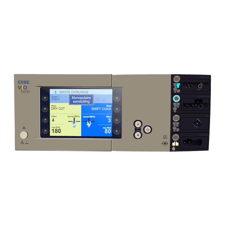
Page 11: Controls
This chapter contains an overview of the controls of the unit(s). The rel- evant User Manual for the unit(s), knowledge of which is assumed for servicing work, provides detailed information about how to use the unit(s). Controls at the front VIO 300 D Fig. 3-1 Power Switch 2–9 Selection buttons... -
Page 12: Controls At The Rear
3 • Controls Controls at the rear Fig. 3-2 Footswitch sockets ECB socket (Erbe Communication Bus) Potential equalization terminal Power supply module with fuses / 84... -
Page 13: Technical Data
4 • Technical Data CHAPTER 4 Technical Data Power connection Rated supply voltage 100 V – 120 V ± 10 % 220 V – 240 V ± 10 % Rated supply frequency 50 / 60 Hz 50 / 60 Hz Line current Power input in standby mode 40 watts... - Page 14 4 • Technical Data Acclimatizing If the unit has been stored or transported at temperatures below +10 °C or above +40 °C, the unit will require approx. 3 hours to acclimatize at room temperature. Standards Classification according to EC Directive 93/42/EEC II b Protection class as per EN 60 601-1 Type as per EN 60 601-1...
-
Page 15: Setup
5 • Setup CHAPTER 5 Setup General information This unit has two Setup levels. The first level is accessible to users and ser- vice staff. The second level is only for use by the service staff. Overview of settings for Setup level 1 Accessible to users and service personnel. -
Page 16: Overview Of Settings For Setup Level 2
5 • Setup Setting Available from Description AUTO V 2.1.x Input of start delay for the AUTO START function. START 2 The start delay value for AUTO START 2 depends on the value entered for AUTO START 1 but is always above the start delay value of AUTO START 1. - Page 17 5 • Setup Setting Available from Description Expert mode V 2.1.x If the expert mode is activated, the following settings are also avail- able: – Temperature monitoring for neutral electrodes – Advanced setting options for ENDO CUT I and Q –...
- Page 18 5 • Setup Setting Available from Description °-Modes V 2.2.x Activation/deactivation of the ° modes Next safety V 2.1.x Self-explanatory. check Test pro- V 2.1.x Error list: grams Stores all errors detected and signaled by the control panel. V 2.1.x Event list:...
- Page 19 5 • Setup Setting Available from Description V 2.1.x Upgrade list: Indicates which upgrades have been installed. V 2.1.x Reset Passwords: Deactivates all passwords assigned for user programs. It is not possi- ble to delete only one password for a specific user program. The assigned passwords are activated again after restarting the unit.
-
Page 20: Call Up Setup
(a) with the Down button or (b) with the selection button next to the "next" menu item. Only variant (a) is used in this manual. VIO 300 D Fig. 5-1 Call up Setup level 1 1. Call up "Guide" window. -
Page 21: Change Settings
5 • Setup Change settings 1. Select the setting to be changed using the adjacent selection button (1...8). The setting is highlighted. 2. Change the setting with the Up/Down buttons (9/10). 3. Confirm the changed setting with the Enter button (12). / 84... - Page 22 5 • Setup / 84...
-
Page 23: Remedying Malfunctions
Safety information ATTENTION! Adjustments, technical tests, modifications, maintenance and repair work may only be performed by Erbe or persons trained by Erbe. If the work is not performed by trained persons, Erbe accepts no liability and warranty rights become void. -
Page 24: A/E-Errors
Description Action nizing code mation module Restart the unit. If the error occurs again, notify Erbe Ser- vice. 2 – 4 Restart the unit. If the error occurs again, notify Erbe Ser- vice. Button error socket 1. Check the keyboard. - Page 25 21 – 23 Restart the unit. If the error occurs again, notify Erbe Ser- vice. Restart the unit. If the error occurs again, notify Erbe Ser- vice. Type detection of socket 1 Check and save the socket fails to agree with the stored configuration in the "Version...
- Page 26 Description Action nizing code mation module 7D + 7E Restart the unit. If the error occurs again, notify Erbe Ser- vice. Operating system error. Information, no fault condi- tion. Internal state incorrect. Information, no fault condi- tion. 81 – 83 Restart the unit.
-
Page 27: B-Errors
1 + 2 Restart the unit. If the error occurs again, notify Erbe Ser- vice. 5 + 6 Restart the unit. If the error occurs again, notify Erbe Ser- vice. Restart the unit. If the error occurs again, notify Erbe Ser- vice. - Page 28 (e.g. by AutoStop) and the activation signal remains (longer than 5 s) (e.g. footswitch). Restart the unit. If the error occurs again, notify Erbe Ser- vice. CAN ID of activation Activation signal during Check the accessories. If the signal (e.g. 100 with switch-on: ...
- Page 29 Occurs if a PowerFail signal age. is received but the PowerFail does not actually happen within 2 s. Restart the unit. If the error occurs again, notify Erbe Ser- vice. CRC check not yet com- Wait until the CRC check is pleted: complete.
- Page 30 Occurs if an error is signaled by the Nessy symmetry monitoring during activa- tion. Restart the unit. If the error occurs again, notify Erbe Ser- vice. Occurs if activation was ter- Check the accessories. If the minated automatically (e.g. error persists, notify Erbe by AutoStop) and tissue is Service.
- Page 31 Check whether the waste gas tube is obstructed. The ERBECRYO 2 is signaling Check the accessories. If the an unknown instrument. error persists, notify Erbe Service. 81 + 82 Restart the unit. If the error occurs again, notify Erbe Ser- vice. / 84...
- Page 32 APC socket 1 recognized: Information, no fault condi- Occurs if an APC socket 1 is tion. recognized. Restart the unit. If the error occurs again, notify Erbe Ser- vice. Single-pedal footswitch rec- Information, no fault condi- ognized: tion.
- Page 33 Action nizing code mation module 8E + 8F Restart the unit. If the error occurs again, notify Erbe Ser- vice. Restart the unit. If the error occurs again, notify Erbe Ser- vice. No status message from Check connectors. Check IES module: ...
- Page 34 6 • Remedying malfunctions Recognizing module: B = Control panel Recog- Error Additional infor- Description Action nizing code mation module Activation type: This activation type is not Assign the correct activation available: type to the instrument. 1 => Dual-pedal Occurs if the user assigns an footswitch both activation signal that is not...
- Page 35 Occurs if the user wants to assign a different mode to an instrument with a fixed mode. Restart the unit. If the error occurs again, notify Erbe Ser- vice. Error number of Footswitch not assigned: Assign the footswitch activa- footswitch (see Occurs if a footswitch which tion.
- Page 36 Occurs if the AutoStart func- tion is assigned while con- tact has already been recognized. AD – AF Restart the unit. If the error occurs again, notify Erbe Ser- vice. NESSY symmetry NESSY symmetry warning: Check the NE accessories. value in %.
- Page 37 tion. Occurs if rinsing of an APC instrument is initiated. B5 + B6 Restart the unit. If the error occurs again, notify Erbe Ser- vice. Permissible limit value of Information, no fault condi- AUTO START activation has tion.
- Page 38 6 • Remedying malfunctions Recognizing module: B = Control panel Recog- Error Additional infor- Description Action nizing code mation module VEM 2 module discon- Information, no fault condi- nected: tion. Occurs if socket extension module VEM 2 is discon- nected from the system.
- Page 39 The HYBRIDtherm instru- Use VIO with the required ment has been connected to software version (V 2.8.x and a VIO that has not been above). => Notify ERBE Ser- enabled for the vice. HYBRIDtherm application. More than one HYBRIDtherm Information, no fault condi- instrument has been con- tion.
- Page 40 6 • Remedying malfunctions Recognizing module: B = Control panel Recog- Error Additional infor- Description Action nizing code mation module D3 + D4 Fully open the bottle valve. Allow the gas bottle to warm up to room temperature. Con- nect a full gas bottle. The input pressure sensor Allow the gas bottle to cool on the ERBECRYO 2 is sig-...
- Page 41 6 • Remedying malfunctions Recognizing module: B = Control panel Recog- Error Additional infor- Description Action nizing code mation module The minimum power for the Information, no fault condi- HYBRIDtherm application tion. has not been reached. Power Down: Information, no fault condi- Occurs if the unit is switched tion.
-
Page 42: C-Errors
Description Action nizing code mation module Restart the unit. If the error occurs again, notify Erbe Ser- vice. 4 – 6 Restart the unit. If the error occurs again, notify Erbe Ser- vice. Restart the unit. If the error occurs again, notify Erbe Ser- vice. - Page 43 Action nizing code mation module 7D – 7F Restart the unit. If the error occurs again, notify Erbe Ser- vice. 81 – 84 Restart the unit. If the error occurs again, notify Erbe Ser- vice. BiCision short circuit detec- Information, no fault condi- tion:...
-
Page 44: D-Errors
ECB fault. Restart the unit. If the error occurs again, notify Erbe Ser- vice. The VIO first receives a one- Information, no fault condi- second signal from the IES 2 tion. and then from the VIO mas- Change the activation ter unit. -
Page 45: F-Errors
6 • Remedying malfunctions F-Errors Recognizing module: F = Footswitch Recog- Error Additional infor- Description Action nizing code mation module CRC error: Replace the ECB footswitch. Occurs if an error is detected during CRC monitoring of the footswitch at start-up (e.g. -
Page 46: 2,3,5,6-Errors
2,3,5,6 1 – 7 Restart the unit. If the error (socket) occurs again, notify Erbe Ser- vice. 2,3,5,6 Overcurrent activation rec- Check the accessories. If the (socket) ognition: error persists, notify Erbe The measurement current Service. - Page 47 Erbe with instrument type. Service. 2,3,5,6 87 – 89 Restart the unit. If the error (socket) occurs again, notify Erbe Ser- vice. 2,3,5,6 8A – 8F Restart the unit. If the error (socket) occurs again, notify Erbe Ser- vice.
-
Page 48: Ne)-Errors
4 (NE) 1 – 8 Restart the unit. If the error occurs again, notify Erbe Ser- vice. 4 (NE) C – E Restart the unit. If the error occurs again, notify Erbe Ser- vice. 4 (NE) 10 + 11 Restart the unit. -
Page 49: 9-Errors
6 • Remedying malfunctions 9-Errors Recognizing module: 9 = Erbe Irrigation Pump EIP 2 Recog- Error Additional infor- Description Action nizing code mation module Restart the unit. If the error occurs again, notify Erbe Ser- vice. Pump lid open at User error:... - Page 50 6 • Remedying malfunctions / 84...
-
Page 51: Maintenance And Servicing
ATTENTION! Adjustments, tests, modifications, maintenance and repair work may only be performed by Erbe or persons trained by Erbe. If the work is not performed by trained persons, Erbe accepts no liability and warranty rights become void. It is recommended that the technical safety check also be performed by Erbe or persons trained by Erbe. -
Page 52: Technical Safety Check - Step By Step
Test equipment, measuring equipment, and auxiliary test equipment (cables, test boxes, etc.) are listed separately at the beginning of each test unit. Where Erbe article numbers are specified, only original Erbe test equipment, measuring equipment, and auxiliary test equipment may be used. -
Page 53: Testing And Measuring Equipment
Testing and measuring equipment IMPORTANT! The following list contains the testing and measuring equipment rec- ommended by Erbe for servicing. Where Erbe article numbers are spec- ified, only original Erbe testing and measuring equipment should be used. Erbe Art. No. -
Page 54: User Manual And Visual Inspections
7 • Maintenance and servicing Erbe Art. No. Description 20100-101 VIO Testbox Symmetry/Resistance (NE asymmetry/critical resistance) 20100-102 VIO Testbox Auto Start/Auto Stop (bipolar start/stop) 20100-019 Testbox spark monitor, 230 V Testbox spark monitor, 120 V 20100-028 User manual and visual inspections •... -
Page 55: Dc Resistance
5. Close all relays in the test program via „All switch on“: – ------ Relays closed – --/-- Relays open 6. Perform the measurement. 7. Switch the test specimen off. DC resistance Testing and measuring equipment Erbe Art. No. Description 20192-127 Patient cable AE Patient cable AE, international 20192-110 20190-045 Electrode handle ICC/ACC –... - Page 56 7 • Maintenance and servicing Test setup WARNING! Across the measuring lines there is the DC voltage of 500 V! In order to avoid injuries, only switch on the test specimen and safety tester when all the electrical connections have been made. Fig.
-
Page 57: Performance Tests
7 • Maintenance and servicing Performance tests Testing and measuring equipment Erbe Art. No. Description 20189-303 Dual-pedal footswitch with ReMode 20194-070 Patient cable NE Patient cable NE, international 20194-075 20100-033 Adapter cable NE Test setup • The test specimen is connected to the power supply via the power cord. -
Page 58: Footswitch Activation
2. Press COAG pedal on the dual-pedal footswitch at least twice. When pressing the pedal there must be an acoustic signal every time (=acknowledgement tone). Footswitch activation Testing and measuring equipment Erbe Art. No. Description 20188-300 Single-pedal footswitch 20189-303... - Page 59 7 • Maintenance and servicing Test procedure 1. Call up Setup level 2 (see page 20). 2. Select the "Test programs" setting. 3. Use the Up button to select "Hardware TP" and press Enter to con- firm. The test specimen switches to the test program mode. 4.
-
Page 60: Fingerswitch Activation
7 • Maintenance and servicing Fingerswitch activation Testing and measuring equipment Erbe Art. No. Description 20192-127 Patient cable AE Patient cable AE, international 20192-110 20190-045 Electrode handle ICC/ACC 20190-115 VIO ReMode electrode handle (only if an MF socket or an MF-2 socket is available) -
Page 61: Instrument Recognition Multifunction Sockets
1. Press the Up button until "Restart" appears. 2. Press Enter to confirm the setting. The test specimen exits the test program mode. Instrument recognition multifunction sockets Testing and measuring equipment Erbe Art. No. Description 20100-152 BiClamp measuring cable (only if a MF socket is available) -
Page 62: Automatic Start Mode
7 • Maintenance and servicing Automatic start mode Testing and measuring equipment Erbe Art. No. Description 20196-045 Bipolar cable Bipolar cable, international 2Pin 22 20196-053 20100-034 Adapter cable bipolar 20100-102 VIO Testbox Auto Start/Auto Stop (bipolar start/stop) Test setup Testbox 20100-102 Fig. -
Page 63: Automatic Stop Mode
2. On the VIO Testbox press button T1. The test specimen must start activation after the set start delay. 3. Press button T2. The test specimen must terminate activation. Automatic stop mode Testing and measuring equipment Erbe Art. No. Description 20196-045 Bipolar cable Bipolar cable, international 2Pin 22... -
Page 64: Spark Monitor
4. Hold down button T3 for approx. 5 s, then let go. Within another 9 s at the latest the test specimen must terminate activation and emit two brief signal tones. Spark monitor Testing and measuring equipment Erbe Art. No. Description 20192-127 Patient cable AE Patient cable AE, international... - Page 65 "Output socket" (select here: 2 = socket slot, MONOPOLAR = arrange- ment with monopolar socket). 6. On the Testbox press button S1. 7. In the test program read off the measured value for "Spark". The tol- erance range is 245 to 285 ERBE. / 84...
-
Page 66: Hf Power Output Cut
7 • Maintenance and servicing HF power output CUT Testing and measuring equipment Erbe Art. No. Description 20192-127 Patient cable AE Patient cable AE, international 20192-110 20190-045 Electrode handle ICC/ACC – Laboratory measuring cable 20194-070 Patient cable NE Patient cable NE, international... - Page 67 • The dual-pedal footswitch with ReMode is connected. 1. The DRY CUT is only standard scope of supply with VIO 300 D electrosurgical units. With VIO 200 D electrosurgical units it can be purchased and installed as an upgrade. For details of how to test DRY CUT with VIO 200 D electrosurgical units see chapter "Performance test upgrades".
- Page 68 7 • Maintenance and servicing Test procedure 1. Set test specimen to: BIPOLAR CUT, Effect 8, 100 watts 2. Set HF power meter to: RL = 500 ohms 3. Activate test specimen via CUT pedal on the footswitch. 4. Determine and document measured value. The tolerance range is 80 to 120 watts.
-
Page 69: Hf Power Output Coagulate
7 • Maintenance and servicing HF power output COAGULATE Testing and measuring equipment Erbe Art. No. Description 20192-127 Patient cable AE Patient cable AE, international 20192-110 20190-045 Electrode handle ICC/ACC – Laboratory measuring cable 20194-070 Patient cable NE Patient cable NE, international... - Page 70 7 • Maintenance and servicing Test procedure 1. Set test specimen to: BIPOLAR FORCED COAG, Effect 2, 90 watts 2. Set HF power meter to: RL = 200 ohms 3. Activate test specimen via COAG pedal on the footswitch. 4. Determine and document measured value. The tolerance range is 72 to 108 watts.
-
Page 71: Performance Test Upgrades
7 • Maintenance and servicing Only relevant with VIO 300 D 1. Set test specimen to: SPRAY COAG, Effect 2, 120 watts 2. Set HF power meter to: RL = 500 ohms 3. Activate test specimen via COAG button on the electrode handle. - Page 72 7 • Maintenance and servicing DRY CUT Test setup (only to be tested as an upgrade with VIO 200 D) HF power meter Fig. 7-10 • The test specimen is connected to the power supply via the power cord. • The levels of power are determined with the HF power meter. The measuring cables are plugged into the HF power meter direct.
- Page 73 7 • Maintenance and servicing ENDO CUT I and Q Test setup IMPORTANT! For these tests in Setup level 2 set the Expert mode to "ON". Oscilloscope High Voltage Differential probe HF power meter Fig. 7-11 • The test setup is designed as shown in the illustration above. •...
- Page 74 7 • Maintenance and servicing 1. Set test specimen to: EndoCut Q, Effect 1, Cutting duration 4, Cutting interval 2 2. Set HF power meter to: RL = 1000 ohms 3. Connect the probe of an oscilloscope to AE and NE. 4.
-
Page 75: Monitor Circuits
7 • Maintenance and servicing Monitor circuits NE monitoring of critical resis- Testing and measuring equipment tance Erbe Art. No. Description single surfaced 20194-070 Patient cable NE return electrodes Patient cable NE, international 20194-075 20100-033 Adapter cable NE 20100-101 VIO Testbox Symmetry/Resistance (NE... - Page 76 2. Activate AUTO CUT via the footswitch. It must be possible to activate the test specimen without error or warning signals. NE monitoring of Testing and measuring equipment critical resistance Erbe Art. No. Description dual surfaced 20194-070 Patient cable NE...
- Page 77 7 • Maintenance and servicing Test set-up and test procedure 1st test step Testbox 20100-101 Fig. 7-15 • The test specimen is connected to the power supply via the power cord. • The test is performed without a load. • The NE socket of the test specimen is connected to the VIO Testbox via the patient cable NE with the adapter cable.
- Page 78 2. Activate AUTO CUT via the footswitch. The test specimen must inhibit activation and emit or display an optical and acoustic warning. NE monitoring of asymmetry Testing and measuring equipment Erbe Art. No. Description 20192-127 Patient cable AE Patient cable AE, international...
- Page 79 7 • Maintenance and servicing Test set-up and test procedure 1st test step Testbox 20100-101 Fig. 7-18 • The test specimen is connected to the power supply via the power cord. • The NE socket of the test specimen is connected to the VIO Testbox via the patient cable NE with the adapter cable.
-
Page 80: Bipolar Resection Adapter (Vio 300 D From V 2.2.X Only)
2 seconds an acoustic warning must be emitted. The test specimen must interrupt activation. Bipolar resection adapter (VIO 300 D from V 2.2.x only) Testing and measuring equipment Erbe Art. No. - Page 81 RESECTOSCOPE VIO MF Fig. 7-21 • The power cord connects the VIO 300 D to the power supply. • The VIO 300 D is switched off. • The bipolar resection adapter is connected to the MF socket of the VIO 300 D.
- Page 82 • The test setup is configured as illustrated above. IMPORTANT! The test is carried out without a connected load. • The power cord connects the VIO 300 D to the power supply. • The bipolar resection adapter is connected to the MF socket of the VIO 300 D.
- Page 83 – Output socket: 3 BIPOLAR (3 = sockets slot, BIPOLAR = arrange- ment with multifuction socket, to which the bipolar resection adapter is connected) 6. Use the footswitch to activate the VIO 300 D. 7. Use the oscilloscope to determine the peak value of the HF output voltage.
- Page 84 VIO MF HF power meter Fig. 7-23 • The power cord connects the VIO 300 D to the power supply. • The bipolar resection adapter is connected to the MF socket of the VIO 300 D. • The bipolar resection adapter is connected to the HF power meter via the measuring cable.
Need help?
Do you have a question about the VIO 300 D and is the answer not in the manual?
Questions and answers