
Subscribe to Our Youtube Channel
Related Manuals for Raymarine DSM300


Summary of Contents for Raymarine DSM300
- Page 1 DSM300 Digital Sounder Module Operation with hsb PLUS Series Displays Document number: 81249-1 Date: November 2004...
-
Page 2: Trademarks And Registered Trademarks
Trademarks and registered trademarks Autohelm, HSB, Raymarine, RayTech Navigator, Sail Pilot, SeaTalk and Sportpilot are registered trademarks of Raymarine Limited. Apelco is a registered trademark of Raymarine Holdings Limited.(Registered in all Major marketing territories.) AST, Autoadapt, Auto GST, Autoseastate, Autotrim, Bidata, Marine Intelligence,... -
Page 3: Table Of Contents
Technical Accuracy ... 8 Chapter 1: Overview ...9 1.1 Introduction ... 9 General ... 10 1.2 Fishfinder (Sonar) Mode Display Features ... 10 1.3 How to Use this Handbook ... 10 Chapter 2: Getting Started ...13 2.1 Introduction ... 13 2.2 Powering on the Sounder Module ... - Page 4 Selecting the Frequency ...54 Using Bottom Lock ...55 Using Zoom ...59 Chapter 5: Sonar Mode Operation ...63 5.1 Introduction ...63 5.2 Interpreting and Adjusting the Sounder Image ...64 Target Indications ...64 Using White Line ...65 DSM300 Operation with PLUS Series Displays...
- Page 5 Adjusting Display Gain (Sensitivity) ... 65 Color Gain ... 67 5.3 Using VRM ... 70 5.4 Waypoints ... 71 Placing a Waypoint ... 72 5.5 MOB ... 73 Appendix A: List of Abbreviations ...75 Index ...79...
- Page 6 DSM300 Operation with PLUS Series Displays...
-
Page 7: Preface
If the transducer cable is accidentally removed while the DSM300 is powered on, remove power from the sounder module, replace the transducer cable, and then return power to the module. As a safety feature, the DSM300 only recognizes that the transducer is connected at power-up. -
Page 8: Emc Conformance
Technical Accuracy To the best of our knowledge, the technical and graphical information contained in this handbook was correct as it went to press. However, the Raymarine policy of continuous improvement and updating may change product specifications without prior notice. As a result, unavoidable differences between the product and handbook may occur from time to time, for which liability cannot be accepted by Raymarine. -
Page 9: Chapter 1: Overview
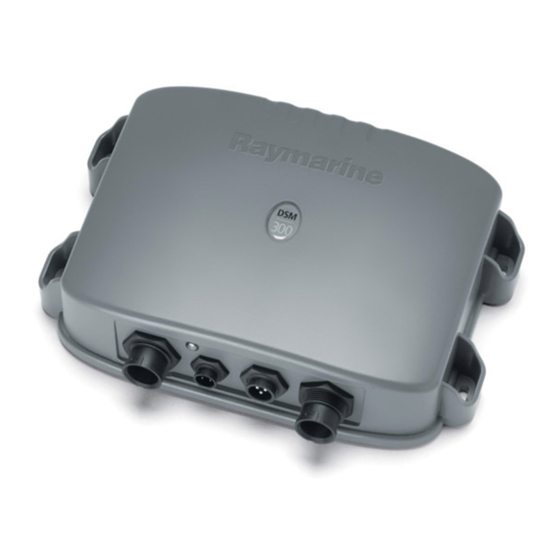
Figure 1-1: DSM300 Digital Sounder Module The DSM300 employs a very high transmission repetition or “ping” rate which, along with the digital adaptive high sample rate receiver, ensures that fish and bottom structure are presented in superb detail and optimal color allocation. The... -
Page 10: General
The DSM300 system is comprised of the Digital Sounder Module, hsb (Pathfinder) Series display unit, transducer, and associated cables. The DSM300 module is waterproof to IPX7 and can be installed either above or below deck. The unit includes connections to: •... - Page 11 Chapter 1: Overview Radome DSM300 Transducer Figure 1-2: DSM300 in an Integrated System PLUS Display used VHF Radio NMEA SeaTalk Power Supply MENU 16/9 HI/LO SCAN WATCH RS-232 Interface Box...
- Page 12 DSM300 Operation with PLUS Series Displays...
-
Page 13: Chapter 2: Getting Started
However, there is a one-minute delay from the time you make the setting change to when the DSM300 places it in memory. If you power down the sounder less than one minute after making a change, the setting is lost. -
Page 14: Selecting Sonar Mode
(color LCD) border and the mode is displayed on the screen. When SONAR mode is shown (as in Figure 2-1), press ENTER or CLEAR. The default soft keys are displayed. The display shows the sounder screen. DSM300 Operation with PLUS Series Displays PLUS Series Radar, Chartplotter or Fishfinder CHART SONAR... -
Page 15: Selecting Repeater Mode
In this case, both units are capable of collecting sonar data. You must tell the display it is to be a repeater for the DSM300 and not a master unit on its own. If your DSM300 is repeating its sonar data over a PLUS Series radar or chartplotter display, the proper settings are made automatically. -
Page 16: Sonar Mode Display
This is a graphical representation of the echoes seen by the DSM300. As time passes, this display scrolls from right to left and becomes a record of the echoes seen. A typical display is shown in Figure 2-2. - Page 17 Chapter 2: Getting Started Power Frequency Auto Zoom Mode Range Indicators Color gain Gain AUTO GCRZFH Cursor, controlled by trackpad Bottom depth Figure 2-2: Typical Display in Sonar Mode Alarm enabled Shallow, Deep Fish 50kHz D6181-1 Target Depth ID On Frequency Alarm Indicators...
-
Page 18: Operating Modes
Table 2-2: Vertical Half-Screen Window Options Full-screen mode Note: Receiving and displaying position data requires a GPS connected to your system. DSM300 Operation with PLUS Series Displays Horizontal Half-Screen Window Options Course Deviation Indicator (CDI), Bearing and Distance Indicator (BDI), Depth/Temp graph, Chart plotter, Radar... -
Page 19: Sonar Options
Sonar Options The DSM300 provides controls to select additional modes: • Frequency – you can select the transducer frequency: 50 kHz for wide cover- age and deep water, 200 kHz for a detailed view, both frequencies simulta- neously or auto-frequency. -
Page 20: Sounder Functions
All of these options are available when the sonar data is displayed in a half-screen window. Sounder Functions The DSM300 includes the following functions: • Automatic or manual selection of scroll speed for bottom graph display • Automatic or manual selection of transducer frequency •... -
Page 21: Simulator Mode
Sonar Mode without data from the transducer. Before using Simulator mode, make sure the display cable is connected from the DSM300 to the display unit and that both the DSM300 and display unit are connected to power. If you have not fully installed the sonar module, you can still operate in Simulator mode by connecting the DSM to the display device. -
Page 22: Viewing Simulator Data
Figure 2-5: Simulator Mode Setup Viewing Simulator Data After you have properly connected and powered up the DSM300 and display units, you can toggle Simulator mode on and off using the Sonar Setup menu. ➤ To view simulated sounder images: 1. -
Page 23: Chapter 3: System Setup
However, there is a one-minute delay from the time you make the setting change to when the DSM300 places it in memory. If you power down the sounder less than one minute after making a change, the setting is lost. - Page 24 5. Once you have set all the desired values, press ENTER to clear the menu and return to the set up soft keys. 6. Press ENTER, MENU, or CLEAR to clear the soft keys and return to the default display. DSM300 Operation with PLUS Series Displays D5019-1...
-
Page 25: System Set Up Parameters
Chapter 3: System Setup 3.3 System Set Up Parameters The SYSTEM SET UP option enables you to set up your system configuration and personal preferences. The following table lists the System menus and their options, shows the factory default setting, and provides a space for you to make a note of your new setting. Each parameter is described in the following subsections. - Page 26 NMEA-OUT SET UP CURSOR ECHO RADAR CURSOR IN CHART CURSOR IN SEATALK CURSOR OUT CURSOR ECHO LOCAL DATE FORMAT DSM300 Operation with PLUS Series Displays Options 30 SECONDS NAUTICAL MILES, STATUTE MILES, KILOMETERS, or KILOYARDS KNOTS, MILES PER HOUR, or...
-
Page 27: Data Boxes
Chapter 3: System Setup Table 3-1: System Set Up Parameters Menu TIME FORMAT TIME OFFSET GPS SOG/COG FILTER COMPASS SET UP LANGUAGE SIMULATOR Data Boxes Press the SELECT BOXES soft key to display the data box sub-menu. This enables you to select up to 6 data boxes that you can display on the sounder. A fixed set of sixteen (nine in the monochrome displays) of these data Notes: items are available for display in the Nav Data half-screen window. -
Page 28: Cursor Reference
The help message is cleared when an action is selected. Soft Keys When the Soft Keys option is set to ON, the default soft keys are displayed if no other operation is in progress. DSM300 Operation with PLUS Series Displays... -
Page 29: Key Beep
Chapter 3: System Setup When the Soft Keys option is set to OFF, the default soft keys are only displayed when a soft key is pressed and they disappear if no operation is performed for 10 seconds. Key Beep This option controls whether or not the keys sound a tone when you press them. MOB Data This option controls whether MOB data is based on position data, or on dead reckoning (DR). -
Page 30: Variation Source
SeaTalk instrument, the new value is used and the manual value that is displayed is updated. The Manual variation value defaults to 0°, so it is important to set up a value if vari- Note: ation is not available from an external source. DSM300 Operation with PLUS Series Displays... -
Page 31: Bridge Nmea Heading
Chapter 3: System Setup Bridge NMEA Heading The display unit sends NMEA input data to the SeaTalk bus. The Bridge NMEA Heading option can be used to prevent NMEA heading data being bridged onto the SeaTalk bus. For example, if you have a course computer connected on SeaTalk and NMEA, and an active compass connected on NMEA (for MARPA), SeaTalk data overrides NMEA data in the course computer. -
Page 32: Cursor Echo
The changes do not take effect until after ENTER is pressed. Consult your NMEA instrumentation documentation to determine which strings should remain ON. The DSM300 outputs the same depth value for DBT and DPT, regardless of the Note: Depth Offset value in Sonar Setup. -
Page 33: Date And Time Settings
LOW. Compass Set Up This option is used to calibrate a Raymarine heading sensor such as the Pathfinder Smart Heading System. Controls are provided for LINEARISE COMPASS, which detects and corrects for heading errors caused by metal objects, and ALIGN HEADING, which matches the displayed heading to a known heading or transit. -
Page 34: Language
Each parameter is described in the following subsections. Table 3-3: Sonar Mode Set Up Parameters Parameter TARGET DEPTH ID COLOR BAR DEPTH DIGIT SIZE DSM300 Operation with PLUS Series Displays Factory Options Default LARGE LARGE SMALL... -
Page 35: Target Depth Id
You can select small or large digits for the depth display. Sonar HSB Mode This parameter only pertains when the display to which you are outputting DSM300 Note: image data is a PLUS Series fishfinder. If your display is a PLUS Series radar or chartplotter display, the REPEATER setting is automatically selected and cannot be changed. -
Page 36: Depth Offset
Note: than one master unit will cause unpredictable results. A sonar MASTER unit is connected directly to the transducer. Only a DSM300 or a PLUS Series fishfinder display can be designated as the master. A REPEATER display is connected via hsb master has collected. -
Page 37: Speed Calibrate
Speed Calibrate If the transducer is equipped with a speed paddle wheel, the DSM300 calculates the speed of the boat through the water. The speed calibrate option enables you to adjust the displayed speed so that it matches your actual speed through the water. -
Page 38: Sonar Simulator
DISPLAY SW VERSION displays the software version of the display unit. MASTER SW VERSION displays the software version and product type of the master unit, which under most circumstances would be the DSM300. MASTER S/N displays the serial number of the master unit, which under normal circumstances would be the DSM300. -
Page 39: Chapter 4: Basic Display Controls
However, there is a one-minute delay from the time you make the setting change to when the DSM300 places it in memory. If you power down the sounder less than one minute after making a change, the setting is lost. -
Page 40: Brightness And Color Settings (Color Displays)
If you set the backlight to a high level, the key lighting is dimmed; if you set the backlight to a low level, the key lighting level is increased. DSM300 Operation with PLUS Series Displays D4895-2... -
Page 41: Adjusting The Brightness
Chapter 4: Basic Display Controls Adjusting the Brightness ➤ To change the screen brightness: 1. Press the MULTI key to display the soft key controls: 2. The LIGHT soft key indicates the brightness level, use the trackpad (up or down) to increase or decrease the setting. You can press and hold the track- pad to change the setting more rapidly. - Page 42 1. Press the MULT I key to display the soft key controls. 2. Press the COLOR SETTINGS soft key. 3. Press the COLOR SET soft key. This toggles between color set 1, bolder colors, and color set 2, softer colors. DSM300 Operation with PLUS Series Displays...
-
Page 43: Controlling The Display
If the data is available on your system, the following display modes can be selected: • Radar • Chart • Sonar (Fishfinder) • Data Log You use the DISPLAY key to select the full-screen display mode. The DISPLAY key also accesses the soft keys for the half-screen window options for additional information. - Page 44 The following information, if available on your system, can be shown: Table 4-1: Horizontal Half-Screen Window Options Full-screen mode Sonar Mode Chart Mode DSM300 Operation with PLUS Series Displays CHART SONAR D6212-1 Horizontal Half-Screen Window Options CDI, BDI, Depth/Temp, Chart, Radar...
- Page 45 Chapter 4: Basic Display Controls Table 4-1: Horizontal Half-Screen Window Options Full-screen mode Radar Mode Data Log Mode • Chart display : If data is available on the display or via the hsb can be displayed. • Radar display : If data is available on the display or via the hsb can be displayed.
- Page 46 CDI Window 50kHz AUTO GCRZFH STEER PORT WAYPOINT 001 Depth/Temperature Window 50kHz AUTO GCRZFH Figure 4-2: Horizontal Half-Screen Windows DSM300 Operation with PLUS Series Displays BDI Window AUTO GCRZFH 0.28 351° 26.8 STEER STARBOARD 03 :59 WAYPOINT 001 Chart Window...
- Page 47 Chapter 4: Basic Display Controls Radar Window 50kHz AUTO GCRZFH Figure 4-3: Radar Half-Screen Window Vertical Half-Screen Window Options You can also use the DISPLAY key to select a data window that is vertically split DISPLAY with the full-screen Sonar mode display. Vertical half-screen windows are only available in Sonar mode.
- Page 48 Figure 4-4: Selecting Vertical Half-Screen Windows Note: Receiving and displaying position data requires that a GPS is connected to your Raymarine system. 50kHz AUTO GC Figure 4-5: Vertical Half-Screen Windows A and B DSM300 Operation with PLUS Series Displays D6191-1 AUTO GC D6207-1 50kHz 81°06^34W 28°17^07N...
-
Page 49: Returning To The Full-Screen Display
Chapter 4: Basic Display Controls 50kHz AUTO GC Rng 2.95nm Brg 093°T Figure 4-6: Vertical Half-Screen Window C Returning to the Full-Screen Display To return to the full-screen display you can turn windows off, as previously described. To return to full-screen display: ➤... -
Page 50: Display Control Functions
Chapter 3. The default data box positions are along the bottom of the display. Each box can be moved to the desired position on the screen using the context-sensitive cursor. DSM300 Operation with PLUS Series Displays D6213-1... -
Page 51: Changing The Scroll Speed
Figure 4-7: Effect of the Scroll Speed The DSM300 defaults to manual scroll adjustment at full speed (100%). Use the trackpad to decrease the scroll speed in 10% increments down to 0% (pause). Unlike automatic adjustment, manual scroll speed is not related to boat speed over the bottom. -
Page 52: Selecting The Power Setting
1. Press the MULTI key ( MULTI knob on CRT radar units) to display the soft key MULTI controls. 2. Press the POWER soft key to toggle between AUTO, LO, or HI power. The selected setting is highlighted. 3. Press ENTER or CLEAR to return to the default screen. DSM300 Operation with PLUS Series Displays... -
Page 53: Changing The Sounder Range
Chapter 4: Basic Display Controls Changing the Sounder Range By default, the sounder automatically adjusts the display range, selecting the shallowest range that keeps the bottom in the lower half of the display window. Shift is disabled (the value is ignored) when auto-range is selected. Alternatively, the RANGE key lets you select the maximum depth displayed on the scrolling bottom and A-Scope displays. -
Page 54: Selecting The Frequency
5. Press ENTER to return to the default display. Selecting the Frequency The DSM300 uses dual frequency sonar—50 kHz and 200 kHz—and can be used in either auto or manual modes. The DSM300 can automatically select the appropriate frequency, based on the current display range. -
Page 55: Using Bottom Lock
Chapter 4: Basic Display Controls Alternatively, you can manually select either frequency, or both frequencies simultaneously (split frequency). Each is suitable for a particular purpose: 50 kHz Frequency When using this frequency, the transducer scans a wide area. The 50 kHz signal penetrates water well, so is good for use in deep water. - Page 56 4. To adjust the range, press the appropriate BTM LOCK RANGE soft key: press the up arrow to select a larger range, press the down arrow to select a smaller range. 5. Press ENTER or CLEAR to return to the default display. DSM300 Operation with PLUS Series Displays...
-
Page 57: Using A-Scope
Chapter 4: Basic Display Controls AUTO GC Z H Figure 4-8: Bottom Lock Display with Split Windows ➤ To reposition the bottom lock image: 1. Use the trackpad to move the cursor to the bottom image until the text BL is displayed near the cursor. - Page 58 If you have split frequency selected, the A-Scope image is displayed in both frequency win- dows. ➤ To remove the A-Scope image: 1. Press the A-SCOPE soft key. 2. Press the A-SCOPE ON OFF soft key to toggle off A-Scope. 3. Press ENTER . DSM300 Operation with PLUS Series Displays...
-
Page 59: Using Zoom
Chapter 4: Basic Display Controls A-SCOPE Mode 1 AUTO G Z Figure 4-9: The Three Modes of A-Scope Using Zoom Zoom enlarges all or part of the scrolling bottom display. You can select automatic zoom so the sounder keeps the bottom in the lower half of the display window. Alternatively, you can manually pick the area to be zoomed. - Page 60 OFF ON 3. Press ENTER or CLEAR to return to the default display. If manual zoom is selected, you can reposition the area of the image that is zoomed. DSM300 Operation with PLUS Series Displays 50kHz AUTO G RZ ZOOM...
- Page 61 Chapter 4: Basic Display Controls ➤ To reposition the zoom window: 1. If you have not already done so, make sure the unit is set to MANUAL zoom. 2. If the cursor is not already visible, press ENTER for the cursor to appear. 3.
- Page 62 AUTO positions the zoom range at the sea bottom. In MANUAL, the range is positioned by moving the Zoom Position Line with the trackpad. DSM300 Operation with PLUS Series Displays...
-
Page 63: Chapter 5: Sonar Mode Operation
Note: The settings described in this chapter are retained when the unit is powered off. However, there is a one-minute delay from the time you change the setting to when the DSM300 places it in memory. If you power down the sounder less than one minute after making a change, the setting is lost. -
Page 64: Interpreting And Adjusting The Sounder Image
5.2 Interpreting and Adjusting the Sounder Image The DSM300 uses sound waves to find fish and show bottom structure. The transducer sends high-frequency sound waves into the water; these sound waves strike fish, the bottom, or other objects in the water and return as echoes. The DSM300 interprets these echoes to present an image of the fish and bottom. -
Page 65: Using White Line
As a result, the sounder typically performs better in automatic mode than manual. For better performance Raymarine recommends selecting AUTO mode for all Gain options. If you change the settings, the new GAIN, COLOR GAIN, or STC values and mode... - Page 66 Automatic gain modes take advantage the hardware’s advanced DSP technology. As a result, the sounder typically achieves a sharper image in any of the automatic gain modes than is possible in manual mode. DSM300 Operation with PLUS Series Displays...
-
Page 67: Color Gain
Use COLOR THRESHOLD with COLOR GAIN to determine how echoes are displayed. The DSM300 provides automatic or manual COLOR GAIN adjustment. Automatic adjustment displays colors based on current conditions, with as many colors as possible, while minimizing noise and clutter. As conditions change the auto-color gain adjusts. -
Page 68: Using Alarms
MANUAL shallow water so that only the strongest echoes are displayed. Although you can manually set the STC level, Raymarine recommends letting the sounder module choose the proper level for you by selecting AUTO STC. Automatic STC mode takes advantage the hardware’s advanced DSP technology, which typically achieves a sharper image in auto mode than is possible in manual mode. -
Page 69: External Alarms
Chapter 5: Sonar Mode Operation The top line status bar shows the condition of the alarms: • indicates an alarm is enabled. The speaker symbol is unfilled until an alarm is triggered and silenced, then the symbol is shown solid. •... -
Page 70: Using Vrm
➤ To switch the VRM on, or re-position an off-screen VRM: 1. Press VRM/EBL. VRM/EBL The VRM is displayed in its last-used position. DSM300 Operation with PLUS Series Displays VRM Distance Unit meters feet feet... -
Page 71: Waypoints
Chapter 5: Sonar Mode Operation The cursor is positioned at the center of the crosshair and has control of the VRM, as indicated by four-way arrow, the solid crosshair and the text VRM. 2. Use the trackpad to position the center of the crosshair over the desired object. -
Page 72: Placing A Waypoint
CLEAR. You can use the EDIT WAYPOINT soft key to name the waypoint as described in Editing Waypoints below. 2. Press CLEAR or ENTER to remove the place waypoint soft keys. DSM300 Operation with PLUS Series Displays D5572-1 D4163-1... -
Page 73: Waypoint List
Chapter 5: Sonar Mode Operation ➤ To place a waypoint as latitude/longitude using the Waypoint List: MARKS 1. Press MARKS, followed by the WAYPOINT LIST soft key. The Waypoint List and associated soft keys are displayed. WAYPOINT LIST POSITION BRG _186° 2. - Page 74 To cancel the MOB, press and hold the MARKS key for 2 seconds. MARKS The MOB symbol and data box are removed. Note: The MOB procedure can also be initiated or cancelled if the appropriate SeaTalk message is received by the display unit. DSM300 Operation with PLUS Series Displays position D6188-1...
-
Page 75: Appendix A: List Of Abbreviations
Appendix A: List of Abbreviations °C Degrees Centigrade °F Degrees Farenheit Amperes Auto Automatic CCFL Cold Cathode Fluorescent Lamp Course Deviation Indicator Course Over Ground Closest Point of Approach Direct Current Digital Selective Calling Digital Sounder Module Electronic Bearing Line Electromagnetic Compatibility Fast Time Constant Global Positioning System... - Page 76 Mini Automatic Radar Plotting Aid Miles per hour Nautical Mile NMEA National Marine Electronics Association Route seconds Ships Heading Marker Statute Miles Speed Over Ground TCPA Time to Closest Point of Approach Time To Go Time Variable Gain DSM300 Operation with PLUS Series Displays...
- Page 77 Appendix A: List of Abbreviations Universal Time Constant Velocity Made Good Variable Range Marker Waypoint Cross Track Error...
- Page 78 DSM300 Operation with PLUS Series Displays...
-
Page 79: Index
Index Abbreviations 75 Alarms 68 Deep Water 68 External 69 Fish Alarm 68 MOB 74 Shallow Water 68 ALARMS Key 68 A-Scope 19 Autopilot Pop Up 25 Background Color 41 BDI Window Options 18 Bearing Mode 25 Bottom Lock 19 Bridge NMEA Heading 31 Brightness Control 41 Cancel MOB 74... - Page 80 Vertical 18 Heading 31 Heading Data Box 25 Help 25 High Voltage 7 Horizontal Half-Screen Windows 18 DSM300 Operation with PLUS Series Displays Key Beep 25 Keys Language 27 Lighting Control Log/Trip Data Box 25 Man Overboard (MOB) - See MOB...
- Page 81 Pilot Data Box 25 Position 74 Position Data Box 25 Power Setting 52 Radar Mode 18 Typical System Diagram 11 Window Options 18 RANGE Key 53 Returning to Full-Screen Display 49 Safety 7 High Voltage 7 Scroll Speed 51 Scrolling Bottom Graph 16 SeaTalk Data 32 Selecting...
- Page 82 Window Options BDI 18 CDI 18 Chart 18 Depth/Temp 18 Full Screen 18 Horizontal Half-Screen 18 Nav Data 18 Radar 18 Sonar 18 Vertical Half-Screen 18 XTE (Cross Track Error) Data Box 25 Zoom 19 DSM300 Operation with PLUS Series Displays...
Need help?
Do you have a question about the DSM300 and is the answer not in the manual?
Questions and answers