Raymarine AIS 350 Installation Instructions Manual
Hide thumbs
Also See for AIS 350:
- Installation instructions manual (64 pages) ,
- Installation instructions manual (68 pages) ,
- Installation instructions manual (68 pages)

Related Manuals for Raymarine AIS 350


Summary of Contents for Raymarine AIS 350
- Page 1 AIS 350 / 650 Installation instructions Da te : 03-2014 Docume nt numbe r: 87140-5 © 2014 Ra yma rine UK Limite d...
- Page 3 Product handbooks The latest versions of all English and translated handbooks are available to download in PDF format from the website www.raymarine.com. Please check the website to ensure you have the latest handbooks.
-
Page 5: Table Of Contents
Contents Chapter 1 Important information......7 2.7 System protocols ............18 Applicability ..............7 Chapter 3 AIS350 Receiver ........21 Certified Installation ............7 3.1 Product overview — AIS350 ........22 RF safety notice ............. 8 3.2 Planning the installation..........22 Safe compass distance ........... - Page 6 4.12 Technical specification ..........76 Chapter 5 Technical support ........77 5.1 Raymarine customer support ........78 Chapter 6 Options and accessories ....... 79 6.1 SeaTalk cables and accessories ......80 6.2 Spares and accessories ..........82 AIS350 / AIS650...
-
Page 7: Chapter 1 Important Information
Raymarine recommends certified installation by a Raymarine • Do NOT connect a device with an AC power source approved installer. A certified installation qualifies for enhanced (such as a PC or laptop) via USB to your Raymarine product warranty benefits. Contact your Raymarine dealer for product. -
Page 8: Rf Safety Notice
It is the also operating. user’s responsibility to use official government charts, notices to mariners, caution and proper navigational skill when operating this or any other Raymarine Water ingress product. Water ingress disclaimer... -
Page 9: Disclaimer
For optimum EMC performance we recommend that wherever possible: Raymarine does not warrant that this product is error-free or that it • Raymarine equipment and cables connected to it are: is compatible with products manufactured by any person or entity other than Raymarine. -
Page 10: Declaration Of Conformity
Whilst the WEEE Directive does not apply to some Technical accuracy Raymarine products, we support its policy and ask you to be aware of how to dispose of this product. To the best of our knowledge, the information in this document was correct at the time it was produced. - Page 11 As a result, Raymarine cannot accept liability for any differences between the product and this document. Please check the Raymarine website (www.raymarine.com) to ensure you have the most up-to-date version(s) of the documentation for your product.
- Page 12 AIS350 / AIS650...
-
Page 13: Chapter 2 Document And Product Information
Chapter 2: Document and product information Chapter contents • 2.1 Document information on page 14 • 2.2 Applicable products on page 14 • 2.3 Document illustrations on page 15 • 2.4 Installation guide on page 15 • 2.5 AIS overview on page 16 •... -
Page 14: Document Information
• troubleshoot problems and obtain technical support if required. AIS 650 Cla s s B Tra ns ce ive r Status This and other Raymarine product documents are available to US B PWR /Data GP S ANT VHF ANT download in PDF format from www.raymarine.com. -
Page 15: Document Illustrations
All images are provided for illustration purposes only. (AIS) device. Refer to the proAIS2 User Manual and the operating manual for your Raymarine Multifunction Display, for instructions on how to configure and operate your AIS system. All documents are available to download as PDFs from www.raymarine.com... -
Page 16: Ais Overview
2.5 AIS overview 2.6 Classes of AIS Your AIS device uses digital radio signals to exchange 'real-time' The AIS350 is a receiver that receives messages from vessels, land base stations, or aids to navigation (AToNs) carrying Class A information between vessels, shore based stations, or aids to navigation (AToNs) on dedicated VHF frequencies. - Page 17 Data Summary *Class B transceivers do not transmit a Gyro heading unless the transceiver is receiving an NMEA HDT sentence from an external Receiver Transceiver Transceiver source. Data (receive) (transmit) (receive) Ship's name Data reporting intervals AIS information is classed as either static or dynamic. Static Type information is broadcast, when data has been amended, or upon Call sign...
-
Page 18: System Protocols
2.7 System protocols Class B systems Ships Dynamic Conditions Reporting rate Your product can be connected to various products and systems to share information and so improve the functionality of the overall 0 to 2 knots 3 Minutes system. These connections may be made using a number of Above 2 knots 30 Seconds different protocols. - Page 19 was specifically intended to allow for a whole network of marine electronics from any manufacturer to communicate on a common bus via standardized message types and formats. NMEA 0183 The NMEA 0183 Data Interface Standard was developed by the National Marine Electronics Association of America. It is an international standard to enable equipment from many different manufacturers to be connected together and share information.
- Page 20 AIS350 / AIS650...
-
Page 21: Chapter 3 Ais350 Receiver
Chapter 3: AIS350 Receiver Chapter contents • 3.1 Product overview — AIS350 on page 22 • 3.2 Planning the installation on page 22 • 3.3 Cables and connections on page 29 • 3.4 Location and mounting on page 38 • 3.5 System checks on page 39 •... -
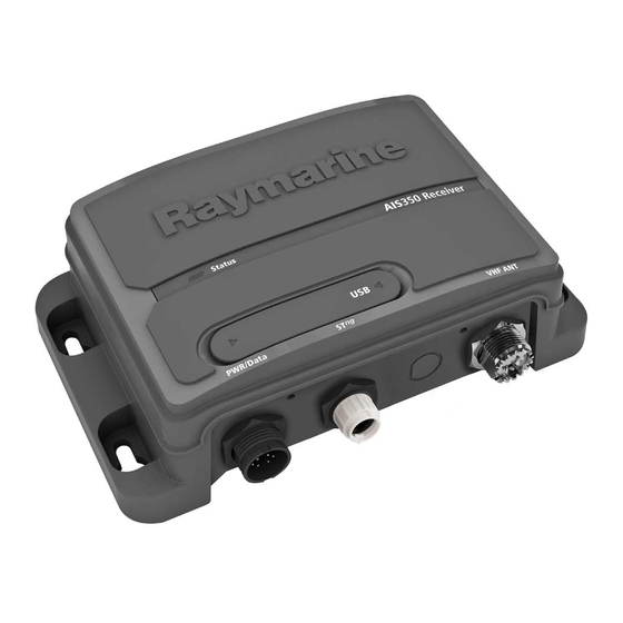
Page 22: Product Overview - Ais350
Installation includes the following activities: Installation Task Plan your installation. Obtain all required equipment and tools. Mount the system components. AIS 350 Re ce ive r S ta tus Route all cables. Drill cable and mounting holes. US B P WR/Da ta VHF ANT Make all connections to equipment. - Page 23 P WR/Da ta VHF ANT the AIS unit in a system that also includes a VHF radio, Raymarine recommends the use of a suitable AIS / VHF splitter (for example, the Raymarine AIS100). This will enable you to use a single VHF antenna for both the AIS and VHF radio units.
- Page 24 Chapter 6 Options and 12 V / 24 V accessories. 12 V / 24 V * • * Some Raymarine SeaTalk Multifunction displays are 12 V NM EA 0183 (38400, GPS) only. Refer to the product’s documentation for more information.
- Page 25 (including part numbers), refer to Chapter 6 Options and 12 V 24 V accessories. • * Some Raymarine SeaTalk Multifunction displays are 12 V SeaT alk ng only. Refer to the product’s documentation for more information. D12085-2 • For more information on general power requirements and...
- Page 26 (including part numbers), refer to Chapter 6 Options and accessories. VHF antenna • * Some Raymarine SeaTalk Multifunction displays are 12 V only. Refer to the product’s documentation for more information. • For more information on general power requirements and...
- Page 27 AIS350 Expanded system example (SeaTalk and NMEA 0183) Description Notes NMEA 0183 VHF radio • If your VHF radio is AIS-capable, NM EA 0183 (4800, DSC) the AIS functions on the radio should be disabled if connecting NM EA 0183 (4800, GPS) the radio to the AIS unit.
- Page 28 Chapter 6 Options and PWR/Da ta VHF ANT accessories. • * Some Raymarine SeaTalk Multifunction displays are 12 V only. Refer to the product’s documentation for more information. • For more information on general power requirements and connections, refer to the Power connection section.
-
Page 29: Cables And Connections
• Unless otherwise stated use only standard cables of the correct type, supplied by Raymarine. • Ensure that any non-Raymarine cables are of the correct quality and gauge. For example, longer power cable runs may require larger wire gauges to minimize voltage drop along the run. - Page 30 Ensure adequate strain relief is provided. Protect connectors from strain and ensure they will not pull out under extreme sea conditions. Circuit isolation AIS 350 Re ce ive r Status Appropriate circuit isolation is required for installations using both AC and DC current: •...
- Page 31 Making data connections — AIS350 To connect your AIS unit to a wider system of electronics including a multifunction display and / or VHF radio: Connections checklist Refer to the drawings in the Typical systems section to understand how the various devices connect together in a system and how the various data signals flow between these devices.
- Page 32 Data connections matrix The following table details the types of data (GPS and / or AIS) that can be exchanged using the various combinations of data connections (Low / High baud rate NMEA 0183; NMEA 2000 / SeaTalk ; USB). It is important to choose the right combination of connections in order to exchange the types of data you require.
- Page 33 US B Important: P WR/Da ta VHF ANT • As detailed in the table above, the 38400 high baud rate NMEA 0183 input and output connections on the AIS unit are NOT linked. This means that the AIS unit cannot receive NMEA 0183 data on the 38400 high baud rate input and then feed it to the 38400 high baud rate output.
- Page 34 • In systems which include a VHF radio, a separate AIS / VHF baud splitter (such as the Raymarine AIS100) is recommended. This splitter device is capable of taking a VHF signal from a single antenna and providing the signal to 2 separate devices (e.g. AIS unit and VHF radio) at the same time.
- Page 35 • Do NOT connect a device with an AC power source Power connection (such as a PC or laptop) via USB to your Raymarine product. Power supply protection • If you need to connect external equipment (such...
- Page 36 Grounding The following requirements apply when grounding Raymarine equipment which does not have a dedicated drain wire or shield: Common ground point The negative wire must be connected to a bonded common ground point, i.
- Page 37 The preferred minimum requirement for the path to ground (bonded VHF ANT or non-bonded) is via a flat tinned copper braid, with a 30 A rating PWR/Data (1/4 inch) or greater. If this is not possible, an equivalent stranded wire conductor may be used, rated as follows: •...
-
Page 38: Location And Mounting
When planning the installation, take the following site requirements into account. AIS requirement S ta tus AIS 350 Re ce ive r This product is NOT approved for use in hazardous/flammable US B atmospheres. Do NOT install in a hazardous/flammable atmosphere... -
Page 39: System Checks
3. Drill the mounting holes using a 3.2 mm (1/8”) drill bit. Using AIS 4. Part fit the screws. The exact method of using AIS depends on which type of Raymarine 5. Place the unit over the screws and move unit down to lock in multifunction display you are using. -
Page 40: Troubleshooting
• The VHF antenna lead is securely connected. 129794 AIS class A static and voyage related No vessel data At the relevant Raymarine multifunction display: data • Place the cursor over the targeted vessel and ensure 129801 AIS address safety messages... -
Page 41: Technical Specification
3.8 Technical specification NMEA 0183 Sentence Title Receiver specification AIVDM Received AIS message Waterproofing IPX2 AIVDO Own vessel AIS report Operating temperature range -15˚C to +55˚C (5˚F to 131˚F) AIALR Alarm condition state Storage temperature range -20˚C to +75˚C (-4˚F to 167˚F) AIACK Alarm acknowledgement Humidity... - Page 42 Weight 280 grams Connectors • VHF Antenna — SO-239 co–axial connector • SeaTalk • NMEA0183 HS — stripped wires • NMEA0183 LS — stripped wires • Power — stripped wires • AIS silent — stripped wires • USB — NMEA0183 AIS350 / AIS650...
-
Page 43: Chapter 4 Ais650 Class B Transceiver
Chapter 4: AIS650 Class B transceiver Chapter contents • 4.1 Product overview — AIS650 on page 44 • 4.2 Static data requirement on page 44 • 4.3 Requirements for USA & Canada on page 45 • 4.4 Requirements for areas outside of USA & Canada on page 48 •... -
Page 44: Product Overview - Ais650
Important: In the United States of America, the MMSI and A or Class B AIS transceivers. Static Data must be entered only by a Raymarine dealer or other appropriately qualified installer of marine communications This information is used to identify and track vessels in the surrounding area and to provide fast, automatic and accurate equipment on board vessels.The user is NOT authorized to do... -
Page 45: Requirements For Usa & Canada
2. This device must accept any interference received, including interference that may cause undesired operation. Changes or modifications to this equipment not expressly approved in writing by Raymarine Incorporated could violate compliance with FCC rules and void the operator’s authority to operate the equipment. - Page 46 Le présent appareil est conforme aux CNR d'Industrie Canada You do not need a license to operate this product within sovereign applicables aux appareils radio exempts de licence. L'exploitation waters of Canada or the US. You will need a license to operate est autorisée aux deux conditions suivantes : this radio outside of Canada or the US.
- Page 47 • connected to the radio before transmitting otherwise input any inaccurate data in this device. The MMSI and Static Data must be entered only by a Raymarine dealer or • located where it will be away from people other appropriately qualified installer of marine communications •...
-
Page 48: Requirements For Areas Outside Of Usa & Canada
4.4 Requirements for areas outside of Denmark Norway USA & Canada Estonia Poland Finland Portugal Maritime Mobile Service Identity (MMSI) France Romania A nine-digit Maritime Mobile Service Identity (MMSI) number is required to operate your AIS Transceiver. In some areas, a radio Germany Slovakia operator licence is required before an MMSI number will be issued. -
Page 49: Planning The Installation
• VHF antenna. If you only have one antenna and you are using Obtain all required equipment and tools. the AIS unit in a system that also includes a VHF radio, Raymarine Mount the system components. recommends the use of a suitable AIS / VHF splitter (for example, the Raymarine AIS100). - Page 50 GPS ANT VHF ANT (including part numbers), refer to Chapter 6 Options and accessories. • * Some Raymarine SeaTalk Multifunction displays are 12 V only. Refer to the product’s documentation for more information. 12 V / 24 V 12 V 12 V / 24 V * •...
- Page 51 (including part numbers), refer to Chapter 6 Options and accessories. NM EA 0183 (38400, GPS + AIS) D13034-1 • * Some Raymarine SeaTalk Multifunction displays are 12 V only. Refer to the product’s documentation for more information. Description Notes • For more information on general power requirements and...
- Page 52 AIS650 Expanded system example (SeaTalk only) Description Notes SeaTalk VHF radio • If your VHF radio is AIS-capable, 12 V / 24 V the AIS functions on the radio should be disabled if connecting the radio to the AIS unit. For instructions on how to do this, Status AIS Sp...
- Page 53 AIS650 Cla s s B Tra ns ce ive r Status accessories. PWR/Data GPS ANT VHF ANT • * Some Raymarine SeaTalk Multifunction displays are 12 V only. Refer to the product’s documentation for more information. 12 V / 24 V * 12 V / 12 V •...
- Page 54 AIS unit by NMEA 0183 and SeaTalk at the same time. • * Some Raymarine SeaTalk Multifunction displays are 12 V only. Refer to the product’s documentation for more information. AIS / VHF splitter For example, AIS100 splitter.
- Page 55 Parts supplied — AIS650 Description Quantity Fixing screws 3 studs, 3 thumb nuts Fixing studs and nuts for GPS receiver (supplied fixings may differ slightly from those shown in the illustration). Status AIS650 Class B Tra ns ce ive r SeaTalk dust cap US B...
-
Page 56: Cables And Connections
• Unless otherwise stated use only standard cables of the correct type, supplied by Raymarine. Strain relief • Ensure that any non-Raymarine cables are of the correct quality Ensure adequate strain relief is provided. Protect connectors from and gauge. For example, longer power cable runs may require strain and ensure they will not pull out under extreme sea conditions. - Page 57 Making data connections — AIS650 Cable shielding Ensure that all data cables are properly shielded that the cable To connect your AIS unit to a wider system of electronics including shielding is intact (e.g. hasn’t been scraped off by being squeezed a multifunction display and / or VHF radio: through a tight area).
- Page 58 Connections checklist For information on how to make USB connections, refer to the connection topic in this section. Refer also to the important information provided in the Do NOT connect a USB device with an AC power source topic. If using NMEA 0183 / 2000, refer to the 3.7 NMEA sentences section to understand which data sentences (PGNs) are supported by the...
- Page 59 Data connections matrix The following table details the types of data (GPS and / or AIS) that can be exchanged using the various combinations of data connections (Low / High baud rate NMEA 0183; NMEA 2000 / SeaTalk ; USB). It is important to choose the right combination of connections in order to exchange the types of data you require.
- Page 60 US B Important: P WR/Da ta VHF ANT • As detailed in the table above, the 38400 high baud rate NMEA 0183 input and output connections on the AIS unit are NOT linked. This means that the AIS unit cannot receive NMEA 0183 data on the 38400 high baud rate input and then feed it to the 38400 high baud rate output.
- Page 61 VHF ANT connection on the AIS unit. • In systems which include a VHF radio, a separate AIS / VHF 4800 splitter (such as the Raymarine AIS100) is recommended. This baud splitter device is capable of taking a VHF signal from a single antenna and providing the signal to 2 separate devices (e.g.
- Page 62 Configuration tab of the ProAIS2 software, as shown in the US B following screenshot: GP S ANT VHF ANT WR/Da ta D12091-1 Note: Raymarine recommends that you make this check before you use the AIS unit for the first time. AIS350 / AIS650...
- Page 63 Sharing a breaker Wire color Signal / Description Where more than 1 piece of equipment shares a breaker you must — Bespoke switch provide protection for the individual circuits. E.g. by connecting an in-line fuse for each power circuit. Orange AIS Silent + Light Green AIS Silent –...
- Page 64 • for runs of >1 m (3 ft), use 8 mm (#8 AWG) or greater. Grounding The following requirements apply when grounding Raymarine In any grounding system, always keep the length of connecting equipment which does not have a dedicated drain wire or shield: braid or wires as short as possible.
- Page 65 To prevent potential grounding problems and possible damage to equipment: • Do NOT connect a device with an AC power source (such as a PC or laptop) via USB to your Raymarine product. • If you need to connect external equipment (such...
- Page 66 The ability to configure the ProAIS2 software to output GPS data from the AIS unit on its NMEA0183 connection is intended for diagnostic purposes only. Raymarine recommends Note: Raymarine recommends that you make this check before that an additional NMEA 0183 or SeaTalk GPS receiver is used you use the AIS unit for the first time.
-
Page 67: Location And Mounting
4.7 Location and mounting Important: The GPS antenna must be mounted in a location that provides a good direct line of site to the entire sky, around the horizon. Site requirements When planning the installation, take the following site requirements Ensure that the selected mounting location is: for the AIS transceiver and GPS antenna, into account. - Page 68 Unit dimensions — AIS650 Mounting Fitting the AIS unit Note: To ensure water resistance the unit must be mounted vertically with the connectors facing down. Note: If you are fitting the AIS unit to fiberglass that has a gelcoat surface, overdrill the surface to prevent the gelcoat from damage when securing the screws.
- Page 69 5. Place the unit over the screws and move unit down to lock in Surface mounting position When surface mounting the GPS antenna, you can route the cable either centrally (Option A) or from the side of the antenna (Option B). 6.
- Page 70 3. Screw the 3 mounting studs (2) into the underside of the antenna. Pole mounting 4. Stick the supplied gasket (3) to the mounting surface, ensuring If you want to pole-mount the GPS antenna, obtain a pole of suitable that the holes on the gasket correspond with the drilled holes. length with a 1 inch 14 TPI thread.
-
Page 71: System Checks
4.10 Troubleshooting section for more information. Configuration Warning: Configure before use This Raymarine product must be correctly configured, to ensure optimum performance and minimize the chances of unsafe or other erroneous data. Configuration requirement After installation and successful switch on, the AIS transceiver must be configured for optimum performance aboard the vessel. - Page 72 You can check the GPS output status of your AIS650 by connecting data programmed into your AIS transceiver. If this information is it to the ProAIS2 software (via the USB connection). Ensure that the incorrect please contact your Raymarine dealer before using the following GNSS sentences are disabled: transceiver.
-
Page 73: Diagnostics
• The transceiver is starting up, or Using AIS • The transceiver has not The exact method of using AIS depends on which type of Raymarine transmitted for more than 2 multifunction display you are using. reporting periods. This could... -
Page 74: Troubleshooting
• The VHF antenna cable is securely connected. • MMSI number has been properly configured (use the No vessel data Using the relevant Raymarine multifunction display: supplied proAIS application to check this). • In the Chart application, place the cursor over the... -
Page 75: Nmea Sentences
4.11 NMEA sentences NMEA 0183 Sentence Title Your product transmits and receives the following NMEA 2000 Parameter Group Numbers (PGNs) and NMEA 0183 sentences: AIVDM Received AIS message NMEA 2000 AIVDO Own vessel AIS report Title AIALR Alarm condition state 129038 Class A position report AIACK... -
Page 76: Technical Specification
4.12 Technical specification Connectors • VHF Antenna — SO-239 co-axial connector Transceiver specification • GPS antenna — TNC co-axial connector Waterproofing IPX2 • SeaTalk Operating temperature range -15˚C to +55˚C (5˚F to 131˚F) • NMEA0183 HS — stripped wires Storage temperature range -20˚C to +75˚C (-4˚F to 167˚F) •... -
Page 77: Chapter 5 Technical Support
Chapter 5: Technical support Chapter contents • 5.1 Raymarine customer support on page 78 Technical support... -
Page 78: Raymarine Customer Support
• Product identity. • Serial number. Raymarine provides a comprehensive customer support service. You can contact customer support through the Raymarine website, • Software application version. telephone and e-mail. If you are unable to resolve a problem, please • System diagrams. -
Page 79: Chapter 6 Options And Accessories
Chapter 6: Options and accessories Chapter contents • 6.1 SeaTalk cables and accessories on page 80 • 6.2 Spares and accessories on page 82 Options and accessories... -
Page 80: Seatalk Cables And Accessories
6.1 SeaTalk cables and accessories Description Part No Notes SeaTalk 5 m (16.4 ft) A06041 SeaTalk cables and accessories for use with compatible products. spur Description Part No Notes SeaTalk 0.4 m (1.3 ft) A06042 SeaTalk starter kit T70134 Includes: elbow spur •... - Page 81 Description Part No Notes Description Part No Notes SeaTalk backbone A06030 DeviceNet adaptor cable E05026 Allows the connection of NMEA (Female) to bare ends. extender 2000 devices to a SeaTalk system. SeaTalk to SeaTalk E22158 Allows the connection of SeaTalk converter kit devices to a SeaTalk system.
-
Page 82: Spares And Accessories
6.2 Spares and accessories The following spares are available for the AIS receiver / transceiver: Part number Description R62241 GPS antenna — passive (with 10 m coaxial cable) — AIS650 only R32162 2 m power/Data cable AIS350 / AIS650... - Page 84 0168 www.ra ym a rin e .c o m...
Need help?
Do you have a question about the AIS 350 and is the answer not in the manual?
Questions and answers