
Related Manuals for ABB Galaxy Millennium J2011002


Summary of Contents for ABB Galaxy Millennium J2011002
- Page 1 PRODUCT MANUAL Galaxy Millennium® SC Controller J2011002 Product Manual Ordering code: 850015641 Page 1 © Copyright 2023 ABB. All rights reserved. Millennium SC_MAN Rev 2.0...
- Page 2 Notice: The information, specifications, and procedures in this manual are subject to change without notice. ABB assumes no responsibility for any errors that may appear in this document. © 2012 abbpowerconversion.com All International Rights Reserved Printed in U.S.A. Page 2 ©...
-
Page 3: Table Of Contents
Record Customer Specified Minimum Configuration ..............40 Remove Existing Controller ......................... 41 Galaxy SC Controller Removal ......................42 MCS Controller Removal ........................60 Other Controller Removal ........................68 Page 3 © Copyright 2023 ABB. All rights reserved. Millennium SC_MAN Rev 2.0... - Page 4 None Load Share Mode........................143 Configuring Load Share Mode ......................143 Network Access - LAN (Gateway) ....................... 143 Slope Thermal Compensation ........................145 Battery Recharge Current Limit ......................... 145 Page 4 © Copyright 2023 ABB. All rights reserved. Millennium SC_MAN Rev 2.0...
-
Page 5: List Of Figures
Figure 20 History Menus ..........................33 Figure 21 Statistics Menus ..........................33 Figure 22 Status Menus 1 of 2 .......................... 34 Figure 23 Status Menus 2 of 2 ......................... 35 Page 5 © Copyright 2023 ABB. All rights reserved. Millennium SC_MAN Rev 2.0... - Page 6 Figure 51 Controller Fuses ..........................94 Figure 52 Controller Drawer .......................... 99 Figure 53 MSC Controller SW202 ........................100 Figure 54 Rectifier Regulation Fuses ......................112 Figure 55 DIP Switches ........................... 181 Page 6 © Copyright 2023 ABB. All rights reserved. Millennium SC_MAN Rev 2.0...
-
Page 7: List Of Tables
Table 42 Threshold Alarms ..........................140 Table 43 Battery Temperature Source Priority ..................... 141 Table 44 Load Share Modes ..........................141 Table 45 External Voltage Input Resistors ....................146 Page 7 © Copyright 2023 ABB. All rights reserved. Millennium SC_MAN Rev 2.0... - Page 8 Table 80 MCS/CCS Wiring Plan & Cross Reference ..................192 Table 81 ECS - 12U Wiring Plan & Cross Reference ..................194 Table 82 Wiring Transfer Plan - Other Controller ..................195 Page 8 © Copyright 2023 ABB. All rights reserved. Millennium SC_MAN Rev 2.0...
- Page 9 This page is intentionally blank. Page 9 © Copyright 2023 ABB. All rights reserved. Millennium SC_MAN Rev 2.0...
-
Page 10: Introduction
Remote Access Control And Multiple Level Password Security • Control and Operation • Plant • Rectifiers • Parallel - Legacy ABB and non-ABB Ferro, SCR, and ABB ECS Switch Mode • Serial GP Protocol - ABB Switch Mode • History • Statistics Abbreviations •... -
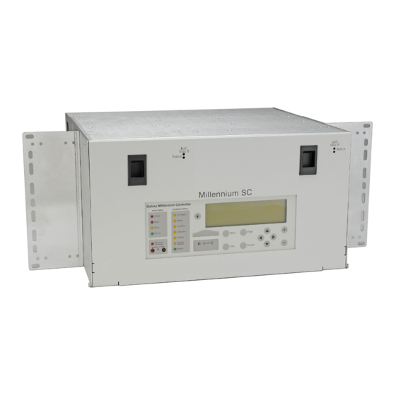
Page 11: Figure 1 Msc Chassis
SC. MSC is physically backwards compatible with SC for ease of field upgrade. Upgrading to the MSC adds newer and more available technologies to the power system. MSC chassis, Figure 1, replaces the SC chassis. Figure 1 MSC Chassis Page 11 © Copyright 2023 ABB. All rights reserved. Millennium SC_MAN Rev 2.0... -
Page 12: Product Description
Controller arrangements are shown in Figure 3. MSC may be installed in new power systems or in operating power systems currently being managed by installed controllers. ABB SC, MCS, and CCS controllers and controllers made by others are suitable for upgrade to MSC. -
Page 13: Figure 3 Controller Arrangements
Figure 3 Controller Arrangements MSC-M2 = MSC without M2 Page 13 © Copyright 2023 ABB. All rights reserved. Millennium SC_MAN Rev 2.0... -
Page 14: Figure 4 Bjc Card Slots
MSC has slots for (2) BJC card slots BJC Rectifier Interface cards for legacy (parallel) rectifiers. Front View with Onboard M2 Controller Figure 4 BJC Card Slots Page 14 © Copyright 2023 ABB. All rights reserved. Millennium SC_MAN Rev 2.0... -
Page 15: Feature Summary
Feature Summary MSC adds support for parallel rectifiers (legacy, non-serial rectifiers) to the functionality of the M2 controller platform. This controller supports ABB’s most extensive controller feature set. Standard System Features Table 1 MSC Standard System Features Monitoring and control of parallel •... -
Page 16: Front Panel User Interface
Derived Channels • Inventory Management • Configuration Backup/Restore Memory • Non-Volatile • Battery Backed • Remote and Local Software Upgrade Front Panel User Interface Figure 5 Front Panel Page 16 © Copyright 2023 ABB. All rights reserved. Millennium SC_MAN Rev 2.0... -
Page 17: Local Serial Access
Menu Driven User Interface • Re-designed user friendly menu driven LCD with similar push- button membrane switch interface • Menu structure similar to other ABB controllers Audible Alarm Buzzer • Integrated on display assembly • May be Enabled/Disabled LEDs •... -
Page 18: Battery Management
Battery Thermal Protect module Boost (BTP) • Auto Boost terminated by time or current • Manual front panel Boost Temperature Disconnect • Programmable high temperature Emergency Power Off • User programmable Page 18 © Copyright 2023 ABB. All rights reserved. Millennium SC_MAN Rev 2.0... -
Page 19: Integrated Monitoring Inputs
1 temperature per probe Integrated Outputs Traditional Office Alarms • 19 Form C alarm outputs • 2 User programmable relay outputs Alarm Battery Supply • 1.3A Fused Page 19 © Copyright 2023 ABB. All rights reserved. Millennium SC_MAN Rev 2.0... -
Page 20: Hardware
MSC mounts in frames – 19, 23, and 25 inch. See Figure 6. It is designed to be physically backwards compatible with existing Galaxy SC rear access controllers for field replacements or upgrades. Figure 6 Controller Dimensions Page 20 © Copyright 2023 ABB. All rights reserved. Millennium SC_MAN Rev 2.0... -
Page 21: Controller Cards
MCR1B / 2B Microprocessor • Front Panel • BSL Alarm Terminations • BSM6 Modem Front View with Onboard M2 Controller Backplane Circuit Card Layout Figure 7 Card Locations Page 21 © Copyright 2023 ABB. All rights reserved. Millennium SC_MAN Rev 2.0... -
Page 22: Figure 8 Mcr1B/2B Circuit Card
Aux Port - RS-232/RS-485 • Remote Peripheral Module (RPM) bus • 10k/30k thermistors • Controller Power and Ground • Plant Voltage and Shunt sense inputs Figure 9 MSCB_FB Fuse Card Page 22 © Copyright 2023 ABB. All rights reserved. Millennium SC_MAN Rev 2.0... -
Page 23: Figure 10 Backplane
For MSC without On-Board M2 RS-485 GP Serial Connection Figure 10 Backplane Modem Option - BSM6 Optional BSM6 Modem card provides dial up access at 33.6k bps. Figure 11 Modem BSM6 Page 23 © Copyright 2023 ABB. All rights reserved. Millennium SC_MAN Rev 2.0... -
Page 24: Figure 12 Alarm Termination Card Bsl3_Msc
MSC can control a total of up to 16 parallel rectifiers. Remote Interface Modules are also required. See Table 40 Rectifier Cables. Figure 13 Rectifier Interface Card Page 24 © Copyright 2023 ABB. All rights reserved. Millennium SC_MAN Rev 2.0... -
Page 25: Supporting Documents
ABB ECS 364 Rectifiers J85501F1L35 Supporting Documents Table 3 Supporting Documents Name Number Millennium SC Controller Ordering Guide J2011002 Galaxy SC Product Manual 850015641 Millennium Controller Product Manual 108324765 Page 25 © Copyright 2023 ABB. All rights reserved. Millennium SC_MAN Rev 2.0... -
Page 26: Front Panel
• Configure • Control • View Status • View History • View Statistics • Perform Diagnostics These menu operations are accomplished by navigating through different screens. Page 26 © Copyright 2023 ABB. All rights reserved. Millennium SC_MAN Rev 2.0... -
Page 27: Lcd
(Critical, Major, Minor, Nominal) of the various alarms. Operation of the status LEDs can be reconfigured via the local or remote controller interfaces. Page 27 © Copyright 2023 ABB. All rights reserved. Millennium SC_MAN Rev 2.0... -
Page 28: Push-Button Keys
A ground referenced RS-232 local port is provided at the front of the display to allow easy connection to a personal computer or terminal using ANSI T1.317 object oriented command language. ABB’s EasyView is also available to provide a user friendly system interface locally or remotely. See Figure 16. -
Page 29: Alarm Buzzer
Audible on PMJ Audible on PMN Contrast Adjust Press the key to change the display contrast. Repeat or hold the button until the desired contrast is reached. Page 29 © Copyright 2023 ABB. All rights reserved. Millennium SC_MAN Rev 2.0... -
Page 30: Display Menus
Display Menus Configuration Menus Figure 17 Configuration Menus 1 of 2 Page 30 © Copyright 2023 ABB. All rights reserved. Millennium SC_MAN Rev 2.0... -
Page 31: Figure 18 Configuration Menus 2 Of 2
Figure 18 Configuration Menus 2 of 2 Page 31 © Copyright 2023 ABB. All rights reserved. Millennium SC_MAN Rev 2.0... -
Page 32: Control And Operations Menus
Control and Operations Menus Figure 19 Control and Operations Menus Page 32 © Copyright 2023 ABB. All rights reserved. Millennium SC_MAN Rev 2.0... -
Page 33: History Menus
History Menus Figure 20 History Menus Statistics Menus Figure 21 Statistics Menus Page 33 © Copyright 2023 ABB. All rights reserved. Millennium SC_MAN Rev 2.0... -
Page 34: Status Menus
Status Menus Figure 22 Status Menus 1 of 2 Page 34 © Copyright 2023 ABB. All rights reserved. Millennium SC_MAN Rev 2.0... -
Page 35: Figure 23 Status Menus 2 Of 2
Figure 23 Status Menus 2 of 2 Page 35 © Copyright 2023 ABB. All rights reserved. Millennium SC_MAN Rev 2.0... -
Page 36: Installation
Rectifier interface Cards (BJC cards or BJCs) determine the Rectifier IDs of their rectifier positions. The switch and jumper that set rectifier IDs are accessible only when the BJC card is not installed. Page 36 © Copyright 2023 ABB. All rights reserved. Millennium SC_MAN Rev 2.0... -
Page 37: Figure 24 Ric Id Setting
• Single BJC Type Systems Plants with only ABB(AT&T) type rectifiers or with only non-ABB(AT&T) type rectifiers will use a single type of BJCs - either all BJC1_MSCs or all BJC2_MSCs. In this case, set BJC First Rectifier IDs so that they are consecutive. -
Page 38: Table 5 Rectifier Interface Cards First Id Settings
Multiple BJC Type Systems Plants with a combination of ABB(AT&T) type rectifiers and non-ABB(AT&T) type rectifiers will use both BJC1_MSCs and BJC2_MSCs. In this case, set BJC First Rectifier IDs may be set so that they allow consecutive rectifier numbers. -
Page 39: Plan Wiring Transfer From Existing Controller
Table 35 Alarm and Control - Signal Names and BSL Pins • Table 36 Alarm - Descriptions, BLS Pins, and Signal Names • Alarm and Control Signals section Plan is completed. Page 39 © Copyright 2023 ABB. All rights reserved. Millennium SC_MAN Rev 2.0... -
Page 40: Prepare Galaxy Sc Configuration File For Msc Use
Record Customer Specified Minimum Configuration Step Action to Plan Record Customer Specified Minimum Configuration Record customer specified configuration in Table 30 Minimum Configuration and Table 32 Network Settings Configuration. Page 40 © Copyright 2023 ABB. All rights reserved. Millennium SC_MAN Rev 2.0... -
Page 41: Remove Existing Controller
NOTE damage the controller and/or circuit cards. Proceed to the appropriate Controller Removal Section: • Galaxy SC Controller Removal • MCS Controller Removal • Other Controller Removal Page 41 © Copyright 2023 ABB. All rights reserved. Millennium SC_MAN Rev 2.0... -
Page 42: Galaxy Sc Controller Removal
This section provides a method for preparing a Galaxy SC rear access controller for removal. Figure 25 Galaxy SC Controller - Front Figure 26 Galaxy SC Controller - Rear Page 42 © Copyright 2023 ABB. All rights reserved. Millennium SC_MAN Rev 2.0... -
Page 43: Table 6 Galaxy Sc Basic Controller (Bja) Hvsd Dip Switch Settings
BJA High Voltage Shutdown. Convert Switch Settings to Voltage using SW200-201 Table 14 Galaxy SC High Voltage Shutdown Setting -48V. Table 15 Galaxy SC High Voltage Shutdown Setting +/-24V. Page 43 © Copyright 2023 ABB. All rights reserved. Millennium SC_MAN Rev 2.0... -
Page 44: Table 7 Galaxy Sc Basic Controller (Bjb) Dip Switch Settings
Auxiliary port: RS-232 or RS-485. (1 = RS-232, 0 = RS-485 SW204-4-8 Not used SW204-3 Enhanced remote security SW204-2 Remote alarm test SW204-1 Rectifier efficiency algorithm Disabled = User Only access Page 44 © Copyright 2023 ABB. All rights reserved. Millennium SC_MAN Rev 2.0... -
Page 45: Table 9 Galaxy Sc Alarm Threshold Settings
Record this information by selecting the following menus from the front panel display: MENU → CONFIG → PLANT Table 10 Galaxy SC Plant Shunt Settings Shunt I Shunt mV Shunt Type Page 45 © Copyright 2023 ABB. All rights reserved. Millennium SC_MAN Rev 2.0... -
Page 46: Table 11 Galaxy Sc Low Voltage Disconnects Settings
MENU → CONFIG → STC Table 12 Galaxy SC Slope Thermal Compensation Settings STC Enabled/Disabled Nominal Temperature Step Temperature Disconnect Temperature Low Temperature Upper Temperature Raise Voltage Enable Temperature Units Page 46 © Copyright 2023 ABB. All rights reserved. Millennium SC_MAN Rev 2.0... -
Page 47: Figure 27 Lvld Contactor Ebv Card Sw300
To force LVLD contactors closed, place SW300 in the up position as shown in Figure 27 and Figure 28. Figure 27 LVLD Contactor EBV Card SW300 Page 47 © Copyright 2023 ABB. All rights reserved. Millennium SC_MAN Rev 2.0... -
Page 48: Figure 28 Lvbd Contactor Control Bjn Card Sw300
Control Card and Switch To Force Closed, Change to Load EBV – SW300 UP for ½ height cabinets Battery BJN – SW300 Down for full height cabinets Page 48 © Copyright 2023 ABB. All rights reserved. Millennium SC_MAN Rev 2.0... -
Page 49: Table 14 Galaxy Sc High Voltage Shutdown Setting -48V
Table 14 Galaxy SC High Voltage Shutdown Setting -48V SW201 Bottom SW200 Top Voltage 50.00 50.50 51.00 51.50 52.00 52.50 53.00 53.50 .*.60 (default) 54.00 54.50 Page 49 © Copyright 2023 ABB. All rights reserved. Millennium SC_MAN Rev 2.0... - Page 50 Table 14 Galaxy SC High Voltage Shutdown Setting -48V SW201 Bottom SW200 Top Voltage 55.00 55.50 56.00 56.50 57.00 57.50 58.00 58.50 59.00 59.50 .60.00 *Default setting = 53.60 1 = closed 0 = open Page 50 © Copyright 2023 ABB. All rights reserved. Millennium SC_MAN Rev 2.0...
-
Page 51: Table 15 Galaxy Sc High Voltage Shutdown Setting -+/-24V
Table 15 Galaxy SC High Voltage Shutdown Setting -+/-24V SW201 Bottom SW200 Top Voltage 24.80 25.00 25.25 25.50 25.75 26.00 26.25 26.50 26.75 .*.80 (default) 27.00 Page 51 © Copyright 2023 ABB. All rights reserved. Millennium SC_MAN Rev 2.0... - Page 52 Table 15 Galaxy SC High Voltage Shutdown Setting -+/-24V SW201 Bottom SW200 Top Voltage 27.25 27.50 27.75 28.00 28.25 28.50 28.75 29.00 29.25 Page 52 © Copyright 2023 ABB. All rights reserved. Millennium SC_MAN Rev 2.0...
- Page 53 Table 15 Galaxy SC High Voltage Shutdown Setting -+/-24V SW201 Bottom SW200 Top Voltage 29.50 29.75 30.00 30.25 30.50 30.75 31.00 *Default setting = 26.80 1 = closed 0 = open Page 53 © Copyright 2023 ABB. All rights reserved. Millennium SC_MAN Rev 2.0...
- Page 54 When parallel rectifier regulation fuses are pulled, the following will occur: • The rectifier will switch to internal regulation. ABB rectifiers automatically switch to internal regulation. • Non-ABB rectifiers must be manually configured for internal regulation. • • Consult the rectifier manual for method of configuration for internal regulation. •...
-
Page 55: Figure 29 Galaxy Sc Rectifier Fuses
Observe and record the output current of each rectifier. Turn the rectifier power switch OFF, regardless of whether a readjustment is necessary. Is the rectifier a ABB rectifier with automatic internal voltage sense? Yes – Proceed to Step 6. No – Proceed. - Page 56 Is there a phone cable attached to the Modem Port Interface Card installed on the rear of the Galaxy SC controller at Connector P101 (see Figure 26)? Yes – No – proceed 1. Mark, Tag, and Remove, and Insulate the cable. 2. Proceed Page 56 © Copyright 2023 ABB. All rights reserved. Millennium SC_MAN Rev 2.0...
-
Page 57: Figure 30 Galaxy Sc Tb2 And Tb3
Mark, Tag, Remove, and Insulate all connections terminating on TB2 and TB3. You may need to reference a controller product manual for labeling the connections. Page 57 © Copyright 2023 ABB. All rights reserved. Millennium SC_MAN Rev 2.0... -
Page 58: Figure 31 Galaxy Sc Tb1 Plant Connections
Remove all 8 controller fuses using a fuse puller (see Figure 32 Galaxy SC Controller Fuses) Mark, Tag, Insulate, and Remove all wires from TB1 on the front of the Galaxy SC. Remove these wires from the controller chassis. Page 58 © Copyright 2023 ABB. All rights reserved. Millennium SC_MAN Rev 2.0... - Page 59 Galaxy SC out of the bay, using a second person for support. CAUTION: Use two people, one supporting the controller. The SC weighs about 35 pounds. Controller removal is complete. Page 59 © Copyright 2023 ABB. All rights reserved. Millennium SC_MAN Rev 2.0...
-
Page 60: Mcs Controller Removal
Identify the power converter card (ED-83011 series or ED83010 series) in the left most position of the right-hand card cage. Pull down on the lock lever of the converter to power down the converter. Repeat this step for all converters. Page 60 © Copyright 2023 ABB. All rights reserved. Millennium SC_MAN Rev 2.0... - Page 61 Observe and record the current on the rectifiers if an adjustment is necessary. Turn the rectifier power switch OFF, regardless of whether a readjustment is necessary. Is the rectifier a ABB rectifier with automatic internal voltage sense? Yes – Proceed to Step 6.
-
Page 62: Figure 34 Mcs Tb1 Alarm Connections
Disconnect Other MCS Connections Figure 34 MCS TB1 Alarm Connections Page 62 © Copyright 2023 ABB. All rights reserved. Millennium SC_MAN Rev 2.0... - Page 63 Examples follow: • Telephone lines • Remote interface cables Make sure that office records are present. Refer to Table 80 MCS/CCS Wiring Plan & Cross Reference. Page 63 © Copyright 2023 ABB. All rights reserved. Millennium SC_MAN Rev 2.0...
-
Page 64: Figure 35 Mcs Auxiliary Board (Cp2)
Table 17 Battery on Discharge S2 HV 53.00 / 26.00 Table 18 High Voltage - Float S3 HV 55.00 / 28.50 Table 19 High Voltage - Equalize Page 64 © Copyright 2023 ABB. All rights reserved. Millennium SC_MAN Rev 2.0... -
Page 65: Table 17 Mcs-Bd And Lv2 Alarm Settings - S1
25.70 53.00 50.00 26.60 25.10 52.60 49.80 26.60 25.10 52.50 49.50 26.10 24.60 52.00 49.00 26.00 24.50 51.90 48.90 25.90 24.40 51.40 48.40 25.50 24.00 51.25 48.25 Page 65 © Copyright 2023 ABB. All rights reserved. Millennium SC_MAN Rev 2.0... -
Page 66: Table 18 Mcs High Voltage Shutdown / Float - S2
54.50 27.80 54.00 27.75 54.00 27.30 53.50 27.25 53.50 26.75 53.00 Switch S2.5 will be open for 48 volt system and closed for a 24 volt system. Page 66 © Copyright 2023 ABB. All rights reserved. Millennium SC_MAN Rev 2.0... -
Page 67: Table 19 Mcs High Voltage Shutdown / Equalize - S3
Remove the mounting bolts on both sides of the MCS. Slide the MCS out of the bay, using the second person for support. CAUTION: Use two people, one supporting the controller. The MCS weighs about 35 pounds. Controller removal is complete. Page 67 © Copyright 2023 ABB. All rights reserved. Millennium SC_MAN Rev 2.0... -
Page 68: Other Controller Removal
Switch ID, Switch Function, Function Setting (Enable / Disable, ON / OFF, etc.) Table 20 Other Controller DIP Switch Settings Function Setting. Switch ID. (SW-#) Switch Function (Enable / Disable) Page 68 © Copyright 2023 ABB. All rights reserved. Millennium SC_MAN Rev 2.0... -
Page 69: Table 21 Other Controller Alarm Threshold Settings
Type – Battery, Load Disconnect Threshold Reconnect Threshold Contactor 2 Type – Battery, Load Disconnect Threshold Reconnect Threshold Contactor 3 Type – Battery, Load Disconnect Threshold Reconnect Threshold Page 69 © Copyright 2023 ABB. All rights reserved. Millennium SC_MAN Rev 2.0... -
Page 70: Table 24 Other Controller Slope Thermal Compensation Settings
If so, then proceed to the next step. Consult the manual for the controller being replaced and associated plant equipment for contactor control method and location. Page 70 © Copyright 2023 ABB. All rights reserved. Millennium SC_MAN Rev 2.0... - Page 71 The rectifier will switch to internal regulation. • ABB rectifiers automatically switch to internal regulation. • CAUTION Non-ABB rectifiers must be manually configured for internal regulation. • Consult the rectifier manual for method of configuration for internal regulation. The system voltage will decrease. •...
- Page 72 Observe and Record the current on the rectifiers if an adjustment is necessary. Turn the rectifier power switch OFF, regardless of whether a readjustment is necessary. Is the rectifier a ABB rectifier with automatic internal voltage sense? Yes – Proceed to Step 6.
- Page 73 Step Action to Remove Modem Connections from Old Controller Locate Modem connections. Mark, Tag and Insulate the Modem connections cables. Remove these connections from the controller housing. Page 73 © Copyright 2023 ABB. All rights reserved. Millennium SC_MAN Rev 2.0...
- Page 74 Remove the mounting bolts on both sides of the controller. Slide the controller out of the bay, using the second person for support. CAUTION: Use two people, one supporting the controller. Controllers may be heavy. Controller removal is complete. Page 74 © Copyright 2023 ABB. All rights reserved. Millennium SC_MAN Rev 2.0...
-
Page 75: Install Controller
Position the MSC housing in the frame or cabinet as desired. Secure the controller to the frame with 3 screws on each side. CAUTION: Use two people, one supporting the controller. The controller is heavy. Page 75 © Copyright 2023 ABB. All rights reserved. Millennium SC_MAN Rev 2.0... -
Page 76: Remove Controller Fuses
Figure 37 Fuse Card Remove and set aside all controller power and rectifier fuses: MODEM, CNTRLLR, BJCA, and BJCB, Rect A1 - Rect A8, and Rect B1 - Rect B8. Page 76 © Copyright 2023 ABB. All rights reserved. Millennium SC_MAN Rev 2.0... -
Page 77: Install Circuit Cards
Install Circuit Cards NOTE: Installation or replacement of cards can be done “hot”; power removal is not necessary, except as noted. Figure 38 Cards Front Figure 39 Cards Rear Page 77 © Copyright 2023 ABB. All rights reserved. Millennium SC_MAN Rev 2.0... -
Page 78: Figure 40 Card Connections
Step Action to Install Rectifier Interface Cards Select the appropriate BJC card for Side A BJC1_MSC CC109167771 for ABB Power (AT&T) type rectifiers BJC2_MSC CC109167788 for non-ABB Power (AT&T) type rectifiers NOTE: For existing Galaxy SC replacement Select BJC_MSC cards of the same type as the replaced BJC cards. -
Page 79: Figure 41 Ric Id Setting
2. Slide the card firmly into position. Position the latch / ejector to secure the card. Repeat from step 1 for a Side B BJC card if present. Page 79 © Copyright 2023 ABB. All rights reserved. Millennium SC_MAN Rev 2.0... -
Page 80: Figure 42 Modem Card Wiring
1. Snap the card onto the two top standoffs 2. Secure the card to the bottom two standoffs with two 845143866 screws Connect the 847756152 cable to the BSL card Page 80 © Copyright 2023 ABB. All rights reserved. Millennium SC_MAN Rev 2.0... -
Page 81: Install Cabling
CAUTION: All ports of the controller except the BSM6 Modem phone port are Intra-building ports. Connect only per Connections - Ports in the General Specifications section – Inputs/ Outputs. Page 81 © Copyright 2023 ABB. All rights reserved. Millennium SC_MAN Rev 2.0... -
Page 82: Figure 44 Controller Connections Rear
Figure 44 Controller Connections Rear Figure 45 Controller Connections Front Page 82 © Copyright 2023 ABB. All rights reserved. Millennium SC_MAN Rev 2.0... -
Page 83: Table 26 Msc Interface Reference
Refer to Table 35 Alarm and Control - Signal Names and BSL Pins and Table 36 Alarm - Descriptions, BLS Pins, and Signal Names for leads terminating on the BSL alarm interface card. Page 83 © Copyright 2023 ABB. All rights reserved. Millennium SC_MAN Rev 2.0... -
Page 84: Figure 46 Bsl4_Msc Alarm Terminations
Terminate the wires by punch down or wire wrap, as provided. Alarm and Control Wiring is done. Punch down insulating caps () are furnished with the controller. Page 84 © Copyright 2023 ABB. All rights reserved. Millennium SC_MAN Rev 2.0... -
Page 85: Table 27 Thermal Probe Types
100K RPM Temperature Probes (TB1 RPM serial bus) Table 28 P3 Compatible Temperature Probe Cables Cable Assembly Used with 848152997 KS20472 round cell thermistor 848152989 ring or paddle type thermistor Page 85 © Copyright 2023 ABB. All rights reserved. Millennium SC_MAN Rev 2.0... -
Page 86: Table 29 Abs Pin Numbers
Carefully align each rectifier cable connector to its intended receptacle on the RIM. Firmly seat each rectifier cable connector on its intended receptacle on the RIM. Plant ground/return source for user alarm systems. Page 86 © Copyright 2023 ABB. All rights reserved. Millennium SC_MAN Rev 2.0... - Page 87 Terminate the RS-232 or RS-485 cable to TB1 on the controller: TB-1 Pin RS-232 Descriptions RS-485 Descriptions FGND FGND 9 or 10 (to cable shield) (to cable shield) Page 87 © Copyright 2023 ABB. All rights reserved. Millennium SC_MAN Rev 2.0...
-
Page 88: Figure 47 Modem Connections
Connect phone cable Tip/Ring conductors to TB1 • NOTE: Tip is TB1 pin 1 (Pin closest to the RJ11 connector) and Ring is Pin 4. Pins 2 and 3 are not used. Page 88 © Copyright 2023 ABB. All rights reserved. Millennium SC_MAN Rev 2.0... -
Page 89: Figure 48 Tb100
If the displayed current is noisy or unstable when local referenced, use Remote Reference rather than Local. Place J5 in position 1-2 and run an external wire from SH REF to the negative side of the shunt. Page 89 © Copyright 2023 ABB. All rights reserved. Millennium SC_MAN Rev 2.0... -
Page 90: Figure 49 Shunt Reference Jumper - J5
TB100 on the Fuse Card. SH REF (Shunt Reference) - Shunt Negative Reference • Is an existing controller being replaced? Yes – Proceed No – Proceed to Step 5 Page 90 © Copyright 2023 ABB. All rights reserved. Millennium SC_MAN Rev 2.0... -
Page 91: Figure 50 Plant Connections Wire-Set - 847411824
If this is not possible, leave the jumper in place. Shunt wiring required only with Millennium SC (with Embedded M2 Controller) and single external load shunt. Page 91 © Copyright 2023 ABB. All rights reserved. Millennium SC_MAN Rev 2.0... -
Page 92: Remote Peripheral Monitoring (Rpm)
Bare wire Shield Connections of the bus wire are NOT polarity sensitive. • There are 2 IN, and 2 OUT connections. Either one may be used. • Page 92 © Copyright 2023 ABB. All rights reserved. Millennium SC_MAN Rev 2.0... - Page 93 Secure the RPM control unit to the base with the spring clips. After approximately 1 minute, the green LED on the front of the module will blink once NOTE approximately every 5 seconds. Page 93 © Copyright 2023 ABB. All rights reserved. Millennium SC_MAN Rev 2.0...
-
Page 94: Power-Up The Controller
Yes – Proceed to one of the following: No – Proceed to • Configure the MSC from Galaxy SC Minimum Configuration. • Configure MSC from MCS • Configure MSC from Other Controller • Page 94 © Copyright 2023 ABB. All rights reserved. Millennium SC_MAN Rev 2.0... - Page 95 Critical = Major Relays Using the front panel, go to Menu→Config→System Settings. Config Crit=Major to: Enabled if Galaxy SC was 1 Disabled if Galaxy SC was 0 Page 95 © Copyright 2023 ABB. All rights reserved. Millennium SC_MAN Rev 2.0...
- Page 96 Not Applicable for MSC Modem Plant Shunt See Table 10 Galaxy SC Plant Shunt Settings. Enter this information, recorded earlier, by selecting the following menus from the front panel display: Page 96 © Copyright 2023 ABB. All rights reserved. Millennium SC_MAN Rev 2.0...
- Page 97 See Table 11 Galaxy SC Low Voltage Disconnects Settings. Enter the Low Voltage Disconnect information recorded earlier by selecting the following menus from the front panel display: Page 97 © Copyright 2023 ABB. All rights reserved. Millennium SC_MAN Rev 2.0...
- Page 98 High Comp Limit (Under High Temp Comp) Raise Voltage Enable Low T Comp (Under Low Temp Comp) Temperature Units Decrease (Under High Temp Comp) Increase (Under Low Temp Comp) Page 98 © Copyright 2023 ABB. All rights reserved. Millennium SC_MAN Rev 2.0...
-
Page 99: Figure 52 Controller Drawer
Loosen the two screws securing the controller drawer. Figure 52 Controller Drawer Slide the controller drawer out. Remove the controller cover 1. Remove screws in each corner (four). 2. Remove the cover Page 99 © Copyright 2023 ABB. All rights reserved. Millennium SC_MAN Rev 2.0... -
Page 100: Figure 53 Msc Controller Sw202
2. Align the drawer screws with the threaded inserts in the chassis. 3. Secure the drawer screws. Configure remaining MSC features per office documentation. Proceed to Minimum Configuration. Page 100 © Copyright 2023 ABB. All rights reserved. Millennium SC_MAN Rev 2.0... - Page 101 Set Battery on Discharge alarm threshold from value in Table 16 MCS DIP Switch Settings. Set Float High Voltage alarm threshold from value in Table 16 MCS DIP Switch Settings. Configure remaining MSC features per office documentation. Proceed to Minimum Configuration. Page 101 © Copyright 2023 ABB. All rights reserved. Millennium SC_MAN Rev 2.0...
- Page 102 Using the front panel, go to Menu→Config→Alarm Test. Config HV Shutdown to: HVSD during Alarm Test Enabled if Galaxy SC was 1 Disabled if Galaxy SC was 0 Page 102 © Copyright 2023 ABB. All rights reserved. Millennium SC_MAN Rev 2.0...
- Page 103 See Table 11 Galaxy SC Low Voltage Disconnects Settings. Enter the Low Voltage Disconnect information recorded earlier, by selecting the following menus from the front panel display: Page 103 © Copyright 2023 ABB. All rights reserved. Millennium SC_MAN Rev 2.0...
- Page 104 High Comp Limit (Under High Temp Comp) Raise Voltage Enable Low T Comp (Under Low Temp Comp) Temperature Units Decrease (Under High Temp Comp) Increase (Under Low Temp Comp) Page 104 © Copyright 2023 ABB. All rights reserved. Millennium SC_MAN Rev 2.0...
- Page 105 EBV – SW300 DOWN DOWN for ½ height cabinets Battery BJN – SW300 UP for full height cabinets Configure remaining MSC features per office documentation. Proceed to Minimum Configuration. Page 105 © Copyright 2023 ABB. All rights reserved. Millennium SC_MAN Rev 2.0...
-
Page 106: Table 30 Minimum Configuration
Set the shunt type: LOAD, BATTERY, or NONE. Type See Shunt Type Set the shunt mV rating (25, 50, 60, 100, 150 mV). Set the shunt rated current (0-99999). Page 106 © Copyright 2023 ABB. All rights reserved. Millennium SC_MAN Rev 2.0... - Page 107 This is used in reserve time prediction and enhanced battery Strings test features. Set the number of battery cells per string. This is used in reserve time prediction and enhanced battery Cells/String test features. Page 107 © Copyright 2023 ABB. All rights reserved. Millennium SC_MAN Rev 2.0...
- Page 108 Low T Comp Enable or Disable low temperature compensation. minimum temperature which thermal Low Comp Limit compensation is active. Sets the slope (mV/°C) for low temperature compensation. Increase Page 108 © Copyright 2023 ABB. All rights reserved. Millennium SC_MAN Rev 2.0...
- Page 109 Contactors 2 and 3 are wired to and control only LOAD contactors. Set contactor disconnect threshold. This setting configures the plant voltage at which the Disconnect contactor will disconnect from the bus. Page 109 © Copyright 2023 ABB. All rights reserved. Millennium SC_MAN Rev 2.0...
-
Page 110: Table 31 Modem Settings Configuration
Set Write Enable as instructed by the customer. Write Enable Local/Remote Access (Settings > Communication > Modem) Front Panel (Configure> Communication Ports > Modem) or Local/Remote Access (Settings > Communication > Modem) Page 110 © Copyright 2023 ABB. All rights reserved. Millennium SC_MAN Rev 2.0... -
Page 111: Table 32 Network Settings Configuration
Front Panel (Configure> Communication Ports > Network Settings) or Local/Remote Access (Network) Local/Remote Access (Settings > Communication > Network) Configure Continued Configure other features as directed by the customer. Page 111 © Copyright 2023 ABB. All rights reserved. Millennium SC_MAN Rev 2.0... -
Page 112: Install Parallel Rectifiers Regulation Fuses
Observe and record the output current of each rectifier. Turn the rectifier power switch OFF, regardless of whether a readjustment is necessary. Is the rectifier a ABB rectifier with automatic internal voltage sense? Yes – Proceed to Step 6. No – Proceed. -
Page 113: Acceptance Test
Some tests will cause a battery discharge. Insure that plant batteries are capable of supporting the load. • Alarms will be generated. Notify the appropriate alarm monitoring personnel. Page 113 © Copyright 2023 ABB. All rights reserved. Millennium SC_MAN Rev 2.0... -
Page 114: Test Sequences
DVM. NOTE: The DVM reading will be the one to change since Rectifier Manager will adjust rectifier outputs as necessary per the calibration performed. Page 114 © Copyright 2023 ABB. All rights reserved. Millennium SC_MAN Rev 2.0... - Page 115 Record the value here ________V. Use the Float Settings Menu Screens, select Set Point and Use the Voltage Alarms Menu Screens. NOTE The next step WILL RAISE the system voltage. Page 115 © Copyright 2023 ABB. All rights reserved. Millennium SC_MAN Rev 2.0...
- Page 116 Change the High Float Alarm threshold value to its original value. Use the Voltage Alarms Menu Screens. Press ENTER to save. Observe: 1. Power Minor alarm (PMN) retires 2. RECT and MIN LEDs are extinguished Page 116 © Copyright 2023 ABB. All rights reserved. Millennium SC_MAN Rev 2.0...
- Page 117 Adjust the dummy load to provide 10 to 30% of the rectifier’s output capacity. Record High Voltage Alarm threshold value here _________V. Use the Voltage Alarms Menu Screens. Page 117 © Copyright 2023 ABB. All rights reserved. Millennium SC_MAN Rev 2.0...
- Page 118 Prior to this occurring, change the value of the system voltage to its original value. • Press ENTER to save the change. Restart the rectifier from the front panel by using the menus: • Page 118 © Copyright 2023 ABB. All rights reserved. Millennium SC_MAN Rev 2.0...
- Page 119 Turn on all rectifiers Controller Observations: 3. PMJ Alarm retires 4. BD and MAJ LEDs are extinguished 5. System Voltage is normal Remove the dummy load from the plant. Page 119 © Copyright 2023 ABB. All rights reserved. Millennium SC_MAN Rev 2.0...
- Page 120 Use the Up/Down Arrows. Select Clear History, and press Enter. Use the Up/Down Arrows. Press Enter again to clear the History Log, Press Escape to return to the menus. Page 120 © Copyright 2023 ABB. All rights reserved. Millennium SC_MAN Rev 2.0...
-
Page 121: Troubleshooting
The Modem health LED illuminated Green. If the LED is not Green first verify cable connections in Modem Card - BSM6 - Option. If connections are correct, replace the modem card. Page 121 © Copyright 2023 ABB. All rights reserved. Millennium SC_MAN Rev 2.0... -
Page 122: Controller Alarm Descriptions
Battery Test Active relays are active and both the BD and VLV alarm thresholds along with STC (Slope Thermal Compensation) are inhibited while the Battery Test is active. Page 122 © Copyright 2023 ABB. All rights reserved. Millennium SC_MAN Rev 2.0... - Page 123 (disconnected). The contactors controlled by the controller’s LVD settings (usually used with some or all Contactor 2 Open LVLD contactors of a plant) are open (disconnected). Page 123 © Copyright 2023 ABB. All rights reserved. Millennium SC_MAN Rev 2.0...
- Page 124 Typically only the capacitor charge circuit fuse alarm is wired here as a minor fuse alarm Page 124 © Copyright 2023 ABB. All rights reserved. Millennium SC_MAN Rev 2.0...
- Page 125 RPM system alarm. A channel measurement on a RPM is outside the DC voltage range Measurement Out of Range designed for that RPM type. Often indicates reversed polarity for measurement leads on a unipolar module type. Page 125 © Copyright 2023 ABB. All rights reserved. Millennium SC_MAN Rev 2.0...
- Page 126 The plant voltage is below the threshold set for VLV. This is a critical alarm, indicating that Very Low Voltage load failures are imminent. ID Not Configured A device on the rectifier/converter serial bus has been recognized without an assigned ID. Page 126 © Copyright 2023 ABB. All rights reserved. Millennium SC_MAN Rev 2.0...
-
Page 127: Clear Events
This feature is used to logically remove serial bus devices that have been physically removed and an alarm generated to indicate this removal. Rectifiers, converters, and BICs are the most common devices that require this feature. Page 127 © Copyright 2023 ABB. All rights reserved. Millennium SC_MAN Rev 2.0... -
Page 128: Specifications
Front panel LCD display and menu keys • 10/100 Base-T port System Configuration Methods • DB9 for RS232 port: T1.317 or EasyView; • Phone line – MODEM option Page 128 © Copyright 2023 ABB. All rights reserved. Millennium SC_MAN Rev 2.0... - Page 129 See Specifications Alarm and Control Signals section. Alarm and Control Inputs See Specifications Alarm and Control Signals section. Alarm Contact Outputs 60VDC at 0.5A Form C Alarm Output Contact Ratings Page 129 © Copyright 2023 ABB. All rights reserved. Millennium SC_MAN Rev 2.0...
- Page 130 Floating means EXT-V and EXT-VR are isolated from all other circuits. For altitudes above 5000 feet (1524 meters), derate the temperature by 3.6 °F per 1000 feet (0.656 °C per 100 meters). Page 130 © Copyright 2023 ABB. All rights reserved. Millennium SC_MAN Rev 2.0...
-
Page 131: Alarm And Control Signals
Signal Name Pin Number Signal Name Pin Number Signal Name PCRAO MJFR PCRAC MNFR PCRAR MNFC TFLT PCRVR MNFO TBST PCRVC TRTN PCRVO PBTR PCREO PCREC ACFR Page 131 © Copyright 2023 ABB. All rights reserved. Millennium SC_MAN Rev 2.0... - Page 132 Table 36 Alarm - Descriptions, BLS Pins, and Signal Names Description BSL Pin Number Signal Name PCRAO Critical-Audio PCRAC PCRAR PCRVR Critical-Visual PCRVC PCRVO PCREO Critical-External PCREC PCRER PMJAR Power Major-Audio PMJAC PMJAO Page 132 © Copyright 2023 ABB. All rights reserved. Millennium SC_MAN Rev 2.0...
-
Page 133: Table 36 Alarm - Descriptions, Bls Pins, And Signal Names
RFAC RFAR High Voltage UR1O User Relay 1 UR1C UR1R CTLRR CTLRC Controller Fail CTLRO UR2O User Relay 2 UR2C UR2R VLVR Very Low Voltage VLVC VLVO Page 133 © Copyright 2023 ABB. All rights reserved. Millennium SC_MAN Rev 2.0... -
Page 134: Fuse Alarm Major (Faj) - Bsl-63
A battery potential input is required, which must use an external 1K ohm, 2W current limiting resistor at the source. A Fuse Alarm Minor is generated when battery potential is received. Page 134 © Copyright 2023 ABB. All rights reserved. Millennium SC_MAN Rev 2.0... -
Page 135: Open String Alarm (Os) - Bsl-72
A battery potential input is required, which must use an external 1K ohm, 2W current limiting resistor at the source if not using standard ABB Power LVD circuit cards or controller. This circuit is used to inform the controller that the monitoring circuit of a Low Voltage Disconnect device has failed. In standard Galaxy Power Systems, the Bay Interface card monitors these alarms and informs the Controller through the serial interface connection. -
Page 136: Rectifier External Sequence Option (Tr1-Tr4) - Bsl-73/79/85/80
CAUTION: Damage to the controller may occur if the USB or RS-232 port is connected to a PC when Discharge Ground (DG) bus is not bonded (connected) to earth ground. Page 136 © Copyright 2023 ABB. All rights reserved. Millennium SC_MAN Rev 2.0... -
Page 137: Rectifier Interface
The use of rectifiers or rectifier interfaces that do not provide for a load reading disables the Energy Management features of the Galaxy Controller. 847865425 comes with a coupler and can extend the serial bus to 200 feet maximum. Page 137 © Copyright 2023 ABB. All rights reserved. Millennium SC_MAN Rev 2.0... -
Page 138: Table 41 Commercial Rectifier Wiring (H285-226 G62)
Manual. An open or closed contact to rectifier ground provided by the (R-BL) rectifier upon being turned off manually. AC Input Failure. A closure to rectifier ground provided by the rectifier (O-R) upon loss of AC input voltage. Page 138 © Copyright 2023 ABB. All rights reserved. Millennium SC_MAN Rev 2.0... -
Page 139: Features Reference
The load current displayed is derived from the total of battery currents and the total of rectifier currents. Page 139 © Copyright 2023 ABB. All rights reserved. Millennium SC_MAN Rev 2.0... -
Page 140: Threshold Alarms
CRIT BD LED is turned ON • CRIT relay is OPERATED This alarm indicates that the system voltage is very low, and that the batteries have discharged to a dangerously low depth. Page 140 © Copyright 2023 ABB. All rights reserved. Millennium SC_MAN Rev 2.0... -
Page 141: Battery Temperature Measurement
Priority 2 temperature sources are only included in determining Battery High Temperature when no Priority 1 sources are present. Serial and non-serial rectifiers both attempt to regulate plant voltage. Page 141 © Copyright 2023 ABB. All rights reserved. Millennium SC_MAN Rev 2.0... -
Page 142: Mixed Load Share Mode
Adjustments to serial rectifier set point occur when balance between serial and non-serial • groups is not within 10%. Monitored rectifiers are those with shunts configured in the controller. Page 142 © Copyright 2023 ABB. All rights reserved. Millennium SC_MAN Rev 2.0... -
Page 143: Serial Load Share Mode
Server Mode Controller acts as the DHCP server, providing IP addresses to other devices on the network. Server mode is suitable only for connection to a local PC. This mode is not compatible with networks with other DHCP servers attached. Page 143 © Copyright 2023 ABB. All rights reserved. Millennium SC_MAN Rev 2.0... - Page 144 Host Name A label assigned to a device, e.g. plant1 Domain Name Name of the domain to which the controller is connected (e.g. ge.com). Together, the Host Name and Domain name form the familiar URL format, e.g. plant1@ABB.com. Network Parameters Parameter...
-
Page 145: Slope Thermal Compensation
This feature is available only on plants without non-serial rectifiers. Battery Recharge Current Limit continuous adjusts plant voltage to limit total battery charge current to not exceed the configured maximum value (amperes). Page 145 © Copyright 2023 ABB. All rights reserved. Millennium SC_MAN Rev 2.0... -
Page 146: External Voltage Input (Ext-V)
Resistors (2 required) 1/8W, 1%, 100ppm/°C Resistor Kit +5Vdc 10.98kΩ 150022227 +30Vdc 115.2kΩ 150022228 +60Vdc 242kΩ 150022229 Resistor Kits include 2 resistor assemblies with pig-tail and butt splice attached. Page 146 © Copyright 2023 ABB. All rights reserved. Millennium SC_MAN Rev 2.0... -
Page 147: Backup And Restore Configuration
“source.gal” is the name of the file to be restored from the PC The ftp transfer terminates with a message indicating success or not. Disconnect from the controller: type bye Page 147 © Copyright 2023 ABB. All rights reserved. Millennium SC_MAN Rev 2.0... - Page 148 Select either Xmodem or ASCII transfer. Start your terminal upload program. The restore session terminates automatically with a message indicating that the configuration restore completed or not. Page 148 © Copyright 2023 ABB. All rights reserved. Millennium SC_MAN Rev 2.0...
- Page 149 This page is intentionally blank. Page 149 © Copyright 2023 ABB. All rights reserved. Millennium SC_MAN Rev 2.0...
-
Page 150: T1.317 Objects And Attributes
Periodic Dial-Out Command Line Notepad Comment Line Modem Initialization String Unit TL1 Condition Description TL1 AID TL1 Condition Type Reminder Test Connected Equipment ID Site ID Site Description System Description Page 150 © Copyright 2023 ABB. All rights reserved. Millennium SC_MAN Rev 2.0... -
Page 151: Table 46 System Objects And Attributes
Temperature Units text C or F Critical Equals Major number 0:no 1:yes (HW,SW) Front Panel Configuration number 0:disable 1:enable (HW,SW) Serial Port Configuration number 0:disable 1:enable (HW,SW) Page 151 © Copyright 2023 ABB. All rights reserved. Millennium SC_MAN Rev 2.0... - Page 152 External Password Reset attrl EPR1 Passwords At Defaults attrl PFD1 Excessive Login Attempts attrl EXL1 Memory Backup Battery Low attrl BBL1 Processor Halt attrl PHT1 Clock Changed attrl CLC1 Page 152 © Copyright 2023 ABB. All rights reserved. Millennium SC_MAN Rev 2.0...
-
Page 153: Table 47 Dc Distribution Objects And Attributes
Phase S Current attrl Phase T Current attrl Phase R Fail Alarm attrl Phase S Alarm attrl Phase T Fail Alarm attrl Master Switch Alarm attrl Page 153 © Copyright 2023 ABB. All rights reserved. Millennium SC_MAN Rev 2.0... -
Page 154: Table 49 Alarm Test Objects And Attributes
A Shunt Type text LOAD, BATTERY, NONE Shunt Current number number (A) Shunt Voltage number 1 - 150 (mV) Monitor Load Shunts number 0:disable 1:enable Page 154 © Copyright 2023 ABB. All rights reserved. Millennium SC_MAN Rev 2.0... - Page 155 FAN1 Alarm Battery Supply ABS1 attrl Sense/control Fuse attrl VSF1 Low Voltage Disconnect Fail LVDA attrl LVDA1 Low Voltage Disconnect attrl LVD1 Open String OSA1 attrl Page 155 © Copyright 2023 ABB. All rights reserved. Millennium SC_MAN Rev 2.0...
- Page 156 High Voltage (HV) attrl HVA1 High Float Voltage attrl HFV1 Other Sub-Objects Boost attrl Rectifier attrl Gnn (01 - 64) Bay Interface Card attrl BICn (1 - 32) Page 156 © Copyright 2023 ABB. All rights reserved. Millennium SC_MAN Rev 2.0...
-
Page 157: Table 51 Bay Interface Card (Bic) Objects And Attributes
Timed Manual Duration number 1 - 80:8 (hours) Auto Multiplication Factor number 1 - 9:5 Current Term Current Thresh number >= 0:50 (A) Alarm Sub-Objects Boost State Alarm attrl Page 157 © Copyright 2023 ABB. All rights reserved. Millennium SC_MAN Rev 2.0... -
Page 158: Table 53 Rectifier Objects And Attributes
PRESENT, MISSING Serial Number text XXXXXXYYLLdddddddd Type text BJCn (1 - 2) Rectifier Bay Identifier text RBnn (01-o 32) Description DESZZ text Rectifier Bay n (1 - 32) Page 158 © Copyright 2023 ABB. All rights reserved. Millennium SC_MAN Rev 2.0... - Page 159 Half Power number 0:inactive 1:active ID Conflict number 0:inactive 1:active Rectifier Current Limit number 0:inactive 1:active Communication Failure number 0:inactive 1:active Rectifier Fan Fail number 0:inactive 1:active Page 159 © Copyright 2023 ABB. All rights reserved. Millennium SC_MAN Rev 2.0...
-
Page 160: Table 54 Converter Objects And Attributes
(0 or 1) or shelf number (0 - 18) r is the converter number within the shelf or carrier (1 - 6) The user may only set the state to ON, STANDBY, or VACANT Page 160 © Copyright 2023 ABB. All rights reserved. Millennium SC_MAN Rev 2.0... -
Page 161: Table 55 Ringer Objects And Attributes
2 = first secondary ringer 3 = second primary ringer 4 = second secondary ringer First ringers are in the odd shelf slot. Second ringers are in the even shelf slot. Page 161 © Copyright 2023 ABB. All rights reserved. Millennium SC_MAN Rev 2.0... -
Page 162: Table 56 Battery Objects And Attributes
COMPLETED CHECK BATTERY INTERRUPTED ACTIVE NOT RUN reserve is hours calculate by last complete test load is load at beginning of test Page 162 © Copyright 2023 ABB. All rights reserved. Millennium SC_MAN Rev 2.0... - Page 163 LMP, LI-ELITE, VALVE-REGULATED, Battery Class text (List in web: FLOODED, VALVE- REG , NICAD, LI-ELITE, LI-LMP) Capacity number number Ah Data Parameter nn (01 to 17) number number Page 163 © Copyright 2023 ABB. All rights reserved. Millennium SC_MAN Rev 2.0...
-
Page 164: Table 57 Disconnect Contactor Objects And Attributes
A contactor configured as a LOAD type cannot be disconnected via a software command. A contactor configured as a BATTERY type may be disconnected via a software command only if another contactor is also configured as a BATTERY type. Page 164 © Copyright 2023 ABB. All rights reserved. Millennium SC_MAN Rev 2.0... -
Page 165: Table 58 Standard Alarm Objects And Attributes
Bay Interface ID Conflict MOR1 Measurement Out Of Range LVDA1 Low Voltage Disconnect Fail RFA1 Rectifier Fail MTC1 Module Type Conflict LVD1 Low Voltage Disconnect ACF1 AC Fail Page 165 © Copyright 2023 ABB. All rights reserved. Millennium SC_MAN Rev 2.0... - Page 166 Voltage Duplicate ID CNF3 Contactor 3 Failed CDID1 Converter ID Conflict MZD1 Voltage ID Not Configured CNF4 Contactor 4 Failed These alarms can be cleared using the CLE command. Page 166 © Copyright 2023 ABB. All rights reserved. Millennium SC_MAN Rev 2.0...
-
Page 167: Table 59 Single Threshold Alarm Objects And Attributes
Low Ambient Temperature -40 - 10 : -40 - 50 (C) AMTH1 High Ambient Temperature 20 - 75 :75 (C) These alarms can be cleared using the CLE command. Page 167 © Copyright 2023 ABB. All rights reserved. Millennium SC_MAN Rev 2.0... -
Page 168: Table 60 Dual Threshold Alarm Objects And Attributes
High Voltage 24.75-29.75:26.8V or 50-60:53.6V 25.75 - 31.75:26.8 or 52 - 60:53.6 (V) HFV1 High Float Voltage 24.75-29.75:26.5V or 50-60:53V 25.75 - 31.75:26.5 or 52 - 60:53 (V) Page 168 © Copyright 2023 ABB. All rights reserved. Millennium SC_MAN Rev 2.0... -
Page 169: Table 61 Events Objects And Attributes
0 - 540 seconds Notify On Occur number 0:no 1:yes Notify On Retire number 0:no 1:yes NAG On Occur number 0:no 1:yes Notify Destination text “”, P1, P2, P3, P4 Page 169 © Copyright 2023 ABB. All rights reserved. Millennium SC_MAN Rev 2.0... -
Page 170: Table 62 Alarm Input Objects And Attributes
ID from 1 to 4 (0 for the controller) nn is the input number from 01 to the number of inputs supported by the distribution interface module Page 170 © Copyright 2023 ABB. All rights reserved. Millennium SC_MAN Rev 2.0... -
Page 171: Table 63 Data Switch Objects And Attributes
20 char (default: ABB\r) Alarms Command text 30 char (default: ALMS\r) Hang-up Command text 20 char (default: BYE\r) Connected Equip Alarm attrl CEAn (1 - 6) Page 171 © Copyright 2023 ABB. All rights reserved. Millennium SC_MAN Rev 2.0... -
Page 172: Table 64 Remote Peripheral Monitor Objects And Attributes
ATTACHED,DETACHED,FAIL,TYPE Status text CONFLICT Channel Type text Value number number (C or F) Measurement Out Of Range number 0:inactive 1:active Value = InputVoltage x ScaleFactor + Offset Page 172 © Copyright 2023 ABB. All rights reserved. Millennium SC_MAN Rev 2.0... -
Page 173: Table 65 Distribution Current Objects And Attributes
Shunt Rated Current number number (A) Shunt Rated Voltage number number (mV) Value number number A Shunt Type defaults: DCMC1 = LOAD DCM01 = BATTERY DCM02-DCM06 = LOAD Page 173 © Copyright 2023 ABB. All rights reserved. Millennium SC_MAN Rev 2.0... -
Page 174: Table 66 Controller Analog Input Objects And Attributes
Derived Chan n Value number number UNI Program Line text “” Unit text “” m is One-Wire module number, c is the channel number in the module Page 174 © Copyright 2023 ABB. All rights reserved. Millennium SC_MAN Rev 2.0... -
Page 175: Table 68 Reporting Objects And Attributes
1, 2 Sunday...Saturday, Daily, Monthly, Interval text Quarterly, Never Time time hh:mm:ss (default: 06:00:00) Command Line 1-10 CL01-10 text “” Alarm Sub-Objects Number Did Not Respond attrl POR1 Page 175 © Copyright 2023 ABB. All rights reserved. Millennium SC_MAN Rev 2.0... -
Page 176: Table 69 Remote Communication Objects And Attributes
0:disable 1:enable SETs OPE causes system reboot not used if DHCP enabled shows DHCP assigned or static IP address 0.0.0.0 will force a DNS lookup of “mailhost” Page 176 © Copyright 2023 ABB. All rights reserved. Millennium SC_MAN Rev 2.0... -
Page 177: Table 70 Configurable Statistics Objects And Attributes
DC1 Busy Hour Stats Description text Busy Hour Stats n (1 -4) Source text Any MET attribute path Start Date date Start Hour number 0 - 23 Page 177 © Copyright 2023 ABB. All rights reserved. Millennium SC_MAN Rev 2.0... -
Page 178: Table 71 Tl1 Management Objects And Attributes
TLnnn ( 001 to 256) Description text TL1n Condition Description text Condition Description text AID1 Condition Type text Condition Type Service Affecting number 0:no 1:yes EQUIPMENT, ENVIRONMENT, Reporting text PRESENCE Page 178 © Copyright 2023 ABB. All rights reserved. Millennium SC_MAN Rev 2.0... -
Page 179: User Defined Object Build Example
- Add a user defined object called CELL1 to the system ADD CELL1,TEMP - Add the attribute TEMP to CELL1 LIN CELL1 TEMP,C701 - Link a temperature monitor channel to CELL1 TEMP Page 179 © Copyright 2023 ABB. All rights reserved. Millennium SC_MAN Rev 2.0... - Page 180 This page is intentionally blank. Page 180 © Copyright 2023 ABB. All rights reserved. Millennium SC_MAN Rev 2.0...
-
Page 181: Factory Defaults
MSC has 8 DIP switch positions (SW202) that may be changed. SW202 is located on the MCR1B card. (See Figure 55) OPEN - DISABLED CLOSE - ENABLED MCR1B/2B Card SW202 Figure 55 DIP Switches Page 181 © Copyright 2023 ABB. All rights reserved. Millennium SC_MAN Rev 2.0... -
Page 182: Table 73 Msc Dip Switch Settings
Change Battery High Temperature Threshold Enable or disable Battery Current Limit Change Battery Limit Threshold Change Battery Contactor Status to “Open” status is prohibited. The change to “Close” status is allowed. Page 182 © Copyright 2023 ABB. All rights reserved. Millennium SC_MAN Rev 2.0... -
Page 183: Voltage Threshold Ranges And Default Values
29.75 26.8 24V Boost 25.75 31.75 26.8 48V Float 50.00 60.00 53.6 48V Boost 52.00 60.00 53.6 Rectifier On Threshold (ROT) 20.00 25.00 22.00 40.00 51.00 44.00 Page 183 © Copyright 2023 ABB. All rights reserved. Millennium SC_MAN Rev 2.0... -
Page 184: Controller Alarm Severity, Led And Relay Default Values
Number Did Not Respond Warning None None Circuit Pack Fail Major CTLR CTLR Controller Fail Major CTLR CTLR Rectifier ID Conflict Major RECT None Energy Management Disabled Warning None None Page 184 © Copyright 2023 ABB. All rights reserved. Millennium SC_MAN Rev 2.0... - Page 185 Thermal Probe Failure Minor CTLR CTLR User Relay Conflict Warning None None Very Low Voltage Critical Sense/Control Fuse Major CTLR CTLR ID Not Configured Major RECT None Page 185 © Copyright 2023 ABB. All rights reserved. Millennium SC_MAN Rev 2.0...
-
Page 186: Spare And Replacement Parts
Terminating Resistor for RPM 406712968 406712968 Inductor Bead for RPM 107330946 Galaxy SC Controller Product Manual (Old Controller) J85501P1L22 Display assembly for MSC 230707-1 Punch down terminal insulating caps Page 186 © Copyright 2023 ABB. All rights reserved. Millennium SC_MAN Rev 2.0... - Page 187 This page is intentionally blank. Page 187 © Copyright 2023 ABB. All rights reserved. Millennium SC_MAN Rev 2.0...
-
Page 188: Alarm And Control Signals Cross Reference
Table 79 Galaxy SC Wiring Plan & Cross Reference Table 80 MCS/CCS Wiring Plan & Cross Reference Table 81 ECS - 12U Wiring Plan & Cross Reference Page 188 © Copyright 2023 ABB. All rights reserved. Millennium SC_MAN Rev 2.0... - Page 189 Galaxy SC “Closed on Alarm”, “Return”, and “Open on Alarm” signals are named here as …C”, “…R”, and “…O” respectively. Note: BSL3_MSC has an “E” prefix before each pin number in (). The BSL4_MSC does not. Page 189 © Copyright 2023 ABB. All rights reserved. Millennium SC_MAN Rev 2.0...
- Page 190 BTPR none TB3 - 28 none RO / ROR is the only signal used by MSC for internal rectifier signaling. ERT / ETRR is no longer required. Page 190 © Copyright 2023 ABB. All rights reserved. Millennium SC_MAN Rev 2.0...
- Page 191 TB2 - 4 THERMINA P500 - 2 THERMB TB2 - 5 THERMINB P500 - 3 RCPP TB2 - 3 RCPP P500 - 4 RCPPR TB2 - 6 RCPP2 Page 191 © Copyright 2023 ABB. All rights reserved. Millennium SC_MAN Rev 2.0...
- Page 192 TB1 - 36 PMNVR BSL - 22 PMNVR MCS/CCS alarms “SI (A)” and “BD” are mutually exclusive when mapped to the Millennium SC controller. Only one may be connected. Page 192 © Copyright 2023 ABB. All rights reserved. Millennium SC_MAN Rev 2.0...
- Page 193 TB100 - SH- Wire DG and DG2 discharge grounds separately to provide maximum meter accuracy. If this is not possible, install a jumper between DG and DG2 terminals. Page 193 © Copyright 2023 ABB. All rights reserved. Millennium SC_MAN Rev 2.0...
- Page 194 MJFER MJFR TB104 - 11 MJFEO MJFO Galaxy SC “Closed on Alarm”, “Return”, and “Open on Alarm” signals are named here as …C”, “…R”, and “…O” respectively. Page 194 © Copyright 2023 ABB. All rights reserved. Millennium SC_MAN Rev 2.0...
-
Page 195: Table 82 Wiring Transfer Plan - Other Controller
BSL - 41 ACFC BSL - 42 ACFO Galaxy SC “Closed on Alarm”, “Return”, and “Open on Alarm” signals are named here as …C”, “…R”, and “…O” respectively. Page 195 © Copyright 2023 ABB. All rights reserved. Millennium SC_MAN Rev 2.0... - Page 196 BSL - 81 RBRPO BSL - 82 I/O-1 BSL - 83 IN-2 (BTP) BSL - 84 LVD1 BSL - 85 BSL - 86 BSL - 87 4-20mA Page 196 © Copyright 2023 ABB. All rights reserved. Millennium SC_MAN Rev 2.0...
- Page 197 TB100 - SH - Wire DG and DG2 discharge grounds separately to provide maximum meter accuracy. If this is not possible, install a jumper between DG and DG2 terminals. Page 197 © Copyright 2023 ABB. All rights reserved. Millennium SC_MAN Rev 2.0...
- Page 198 This page is intentionally blank. Page 198 © Copyright 2023 ABB. All rights reserved. Millennium SC_MAN Rev 2.0...
-
Page 199: Safety
For applications in huts, vaults, and central offices, the equipment chassis must be connected to the system bonding network. Use only GMT fuses provided with safety caps. • Page 199 © Copyright 2023 ABB. All rights reserved. Millennium SC_MAN Rev 2.0... -
Page 200: Warning Statements And Safety Symbols
This symbol is used to identify the need for safety glasses and may sometimes be accompanied by some type of statement, for example: “Fuses can cause arcing and sparks. Risk of eye injury. Always wear safety glasses.” Page 200 © Copyright 2023 ABB. All rights reserved. Millennium SC_MAN Rev 2.0... -
Page 201: Precautions
Personnel with electronic medical devices need to be aware of their restrictions when working around electricity. Page 201 © Copyright 2023 ABB. All rights reserved. Millennium SC_MAN Rev 2.0... - Page 202 This page is intentionally blank. Page 202 © Copyright 2023 ABB. All rights reserved. Millennium SC_MAN Rev 2.0...
-
Page 203: Contacts And Warranty
For customers in the United States, Canada, Puerto Rico, and the US Virgin Islands, please dial +1 877 546 3243 (877 ABB) or for all other countries, please call +1 972 244 9288. This number is staffed from 7:00 am to 5:00 pm USA Central Time Zone (GMT -6), Monday through Friday, on normal business days. - Page 204 WARRANTIES, INCLUDING BUT NOT LIMITED TO WARRANTIES OF MERCHANTABILITY AND FITNESS FOR A PARTICULAR PURPOSE. CUSTOMER’S SOLE AND EXCLUSIVE REMEDY SHALL BE SELLER’S OBLIGATION TO REPAIR, REPLACE, CREDIT, OR REFUND AS SET FORTH ABOVE IN THIS WARRANTY. Page 204 © Copyright 2023 ABB. All rights reserved. Millennium SC_MAN Rev 2.0...
-
Page 205: Revision History
Revision Doc Rev. Description Date Dept./Init Initial release April 2012 Updated as per ABB template 05/25/2023 Page 205 © Copyright 2023 ABB. All rights reserved. Millennium SC_MAN Rev 2.0... - Page 206 – in whole or in parts – is forbid- regard to purchase orders, the agreed particulars shall pre- den without prior written consent of ABB. vail. ABB does not accept any responsibility whatsoever for potential errors or possible lack of information in this docu- Copyright© 2023 ABB ment.
Need help?
Do you have a question about the Galaxy Millennium J2011002 and is the answer not in the manual?
Questions and answers