ABB ACS880-17 Hardware Manual
132...400 kw, 200...450 hp
Hide thumbs
Also See for ACS880-17:
- User manual (58 pages) ,
- Firmware instructions (664 pages) ,
- Firmware manual (604 pages)

Related Manuals for ABB ACS880-17


Summary of Contents for ABB ACS880-17
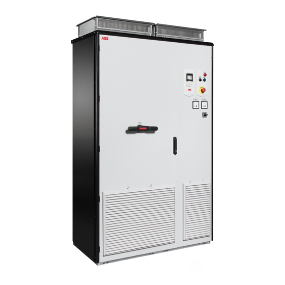
- Page 1 ABB industrial drives Hardware manual ACS880-17 drives (132…400 kW, 200…450 hp)
-
Page 2: Safety Instructions
Document library on the Internet on the inside of the back cover. For manuals not available in the Document library, contact your local ABB representative.The code below opens an online listing of the manuals applicable to this product. ACS880-17 (132…400 kW, 200…450 hp) manuals... - Page 3 Hardware manual ACS880-17 drives (132…400 kW, 200…450 hp) Table of contents 1. Safety instructions 4. Mechanical installation 6. Electrical installation 9. Start-up 2018 ABB Oy. All Rights Reserved. 3AXD50000035158 Rev B EFFECTIVE: 2018-01-18...
- Page 5 Table of contents 1. Safety instructions Contents of this chapter ..........13 Use of warnings and notes .
- Page 6 Channeled air inlet through bottom (option +C128) ......41 Channeled air outlet (option +C130) ........41 Marine construction (option +C121) .
- Page 7 HX_ and AM_ ........... . . 73 Additional requirements for ABB high-output and IP23 motors ....73 Additional requirements for non-ABB high-output and IP23 motors .
- Page 8 Implementing the Safe torque off function ........82 Implementing the ATEX-certified Safe motor disconnection function (option +Q971) .
- Page 9 Grounding the motor cable shield at the motor end ......109 Connecting a PC ............109 Installing option modules .
- Page 10 Recommended annual maintenance actions by the user ....132 Recommended maintenance intervals after start-up ..... . . 132 Cabinet .
- Page 11 IEC ............. . 171 Terminal data for the drive control unit .
- Page 12 Product training ............213 Providing feedback on ABB Drives manuals ....... . 213...
-
Page 13: Contents Of This Chapter
Safety instructions 13 Safety instructions Contents of this chapter This chapter contains the safety instructions which you must obey when you install and operate the drive and do maintenance on the drive. If you ignore the safety instructions, injury, death or damage can occur. Use of warnings and notes Warnings tell you about conditions which can cause injury or death, or damage to the equipment. -
Page 14: General Safety In Installation, Start-Up And Maintenance
14 Safety instructions General safety in installation, start-up and maintenance These instructions are for all personnel that install the drive and do maintenance work on WARNING! Obey these instructions. If you ignore them, injury or death, or damage to the equipment can occur. •... - Page 15 Safety instructions 15 • To prevent the drive module from falling, attach its top lifting lugs with chains to the cabinet frame before you push the module into the cabinet and pull it from the cabinet. Work carefully preferably with help from another person. Keep a constant pressure with one foot on the base of the module to prevent the module from falling on its back.
-
Page 16: Electrical Safety In Installation, Start-Up And Maintenance
16 Safety instructions IEC/EN 61800-5-1, subclause 6.5.3, for example, "THIS MACHINE STARTS AUTOMATICALLY". • The maximum number of drive power-ups is five in ten minutes. Too frequent power- ups can damage the charging circuit of the DC capacitors. • Make sure that any safety circuits (for example, emergency stop and Safe torque off) are validated at start-up. - Page 17 Safety instructions 17 • Use a multimeter with an impedance of at least 1 Mohm. • Make sure that the voltage between the drive input power terminals (L1, L2, L3) and the grounding (PE) busbar is close to 0 V. Measuring holes of the standard drive in the shroud are shown below.
- Page 18 18 Safety instructions • Frame R11: Make sure that the voltage of the drive AC busbars between the drive module and the LCL filter and the grounding (PE) busbar are close to 0 V. Measuring holes of the standard drive in the shroud are shown below. AC busbars...
-
Page 19: Additional Instructions And Notes
Safety instructions 19 • Make sure that the voltage between the DC busbars is close to 0 V. You can measure the voltage through the holes in the cover. Frame R11 7. Install temporary grounding as required by the local regulations. Connect the AC and DC busbars to PE with a temporary grounding tool. -
Page 20: Grounding
20 Safety instructions • The motor cable terminals of the drive are at a dangerous voltage when the input power is on, regardless of whether the motor is running or not. • The DC bus is at a dangerous voltage. •... -
Page 21: Additional Instructions For Permanent Magnet Motor Drives
Safety instructions 21 Additional instructions for permanent magnet motor drives Safety in installation, start-up and maintenance These are additional warnings concerning permanent magnet motor drives. The other safety instructions in this chapter are also valid. WARNING! Obey these instructions. If you ignore them, injury or death and damage to the equipment can occur. - Page 22 22 Safety instructions...
-
Page 23: Contents Of This Chapter
Introduction to the manual 23 Introduction to the manual Contents of this chapter This chapter describes the manual. It contains a flowchart of steps in checking the delivery, installing and starting up the drive. The flowchart refers to chapters/sections in this manual and to other manuals. -
Page 24: Related Documents
24 Introduction to the manual Electrical installation gives instructions on wiring the drive. Control unit of frame R11 contains the default I/O connection diagrams, descriptions of the terminals and technical data for the control unit of the drive. Installation checklist contains a list for checking the mechanical and electrical installation of the drive. -
Page 25: Quick Installation, Commissioning And Operation Flowchart
Introduction to the manual 25 Quick installation, commissioning and operation flowchart Task Plan the electrical installation and acquire the accessories needed Guidelines for planning the (cables, fuses, etc.). electrical installation (page 69) Check the ratings, required cooling air flow, input power connection, Technical data (page 163) compatibility of the motor, motor connection, and other technical... -
Page 26: Terms And Abbreviations
The part of the drive that converts AC to DC for the motor. Includes an LCL filter. converter The line-side converter of the ACS880-17 is also capable of feeding regenerative energy back into the electrical power network. Motor-side The part of the drive that converts DC to AC for the motor. - Page 27 Introduction to the manual 27 Term/ Explanation Abbreviation Safe torque off. See chapter The Safe torque off function (page 199). Control unit type. The drive contains two ZCU control units. One controls the line-side converter, the other the motor-side converter. See also Control unit, control board Drive control...
- Page 28 28 Introduction to the manual...
-
Page 29: Contents Of This Chapter
This chapter briefly describes the operation principle and construction of the drive. Operation principle The ACS880-17 is a four-quadrant, air-cooled, cabinet-installed drive for controlling asynchronous AC induction motors, permanent magnet synchronous motors, AC induction servomotors and ABB synchronous reluctance (SynRM) motors. -
Page 30: Single-Line Circuit Diagram Of The Drive
30 Operation principle and hardware description Single-line circuit diagram of the drive Single-line diagram of R11 Main switch-disconnector (switch-disconnector and separate fuses in frame R11) AC fuses Auxiliary voltage supply fuses Auxiliary circuit protection switch Line contactor inside the drive module. Q2 is controlled by the line-side converter control unit. If Start (Running) command is given to the drive, Q2 is closed and the line-side converter starts to modulate. -
Page 31: Line-Side Converter
Operation principle and hardware description 31 Line-side converter The line-side converter rectifies three-phase AC current to direct current for the intermediate DC link of the drive. The line-side converter is also capable of regenerating, ie. feeding braking energy back into the electrical power network. The following figure shows the simplified main circuit diagram of the line-side converter. -
Page 32: Cabinet Layout
32 Operation principle and hardware description Cabinet layout The layout drawings give an example of the R11 cabinets. The contents of the cabinet depend on the ordered options. For example: • In the lower power R11 cabinets with only a few options the “door” fan is replaced with a shroud (basic cabinet without 24 V auxiliary voltage supply, option +E205 du/dt filter and +E208 common mode filter). - Page 33 Operation principle and hardware description 33 Main breaker and power cabling cubicle Drive module cubicle Swing-out frame on the drive module side open Main switch-disconnector (Q1) handle Drive control panel (see page 40) Operating buttons and door lights (see page 39) Indicators, eg, V-meter and A-meter UL Type V-meter V-meter switch...
- Page 34 34 Operation principle and hardware description Swing-out frame Main fuses for control devices, IP54 fan with option +B055, transformer with option +B055, V- meter (option +G334), starter for auxiliary motor fan (option +M600) Buffering module and power supply unit Terminal blocks X18 and X19 Ground fault monitoring and safety circuit component Optional extension adapters and modules Thermistor and PT100 relays (options +L505, +L506)
- Page 35 Operation principle and hardware description 35 Swing-out frame Auxiliary voltage transformer (T102 with option +B055) and distribution components (see page Auxiliary voltage transformer (T21) and distribution components (see page 91) Line-side control unit Extraction ramp Auxiliary voltage transformer (T101 with options +B055+C128) and distribution components (see page 91)
-
Page 36: Overview Of Power And Control Connections
36 Operation principle and hardware description Overview of power and control connections The diagram shows the power connections and control interfaces of the drive. Connection overview of R11 ACS880-17 Slots 1, 2 and 3 X205 ..V1, V2 ... - Page 37 Operation principle and hardware description 37 Terminal blocks for customer connections installed in the drive cabinet. For the locations, see Overview of power and control connections (page 36). Wiring details are given starting on page 99. Socket for external ISU control Line-side converter DC link Motor-side converter...
-
Page 38: External Control Cable Connection Terminals
38 Operation principle and hardware description External control cable connection terminals Connection terminals of R11 The layout of external control cable connection terminals at the left-hand side of the drive cabinet is shown below. The composition depends on the options selected. X965 Terminals for X969... -
Page 39: Door Switches And Lights
Operation principle and hardware description 39 Door switches and lights Label in English Label in local Description language READY Ready light (option +G327) Run light (option +G328) FAULT Fault light (option +G329) RUN/ENBL Run enable signal switch for the line-side converter with options +Q951, +Q952 and +Q978 OFF Run enable signal off (starting the line-side converter not allowed). -
Page 40: Other Devices On The Door
40 Operation principle and hardware description WARNING! The main disconnecting device does not isolate the input power terminal or V-meter (option +G334) from the power line. To isolate the input power terminals and V-meter, open the main breaker of the supply transformer. Note: The drive is not fitted with an auxiliary voltage switch. -
Page 41: Descriptions Of Cabinet Options
Operation principle and hardware description 41 Descriptions of cabinet options Note: All options are not available for all drive types, do not coexist with certain other options, or may require additional engineering. Check actual availability with ABB. Degree of protection ... -
Page 42: Marine Construction (Option +C121)
42 Operation principle and hardware description Marine construction (option +C121) The option includes the following accessories and features: • reinforced mechanics • grab railings • door flush bolt which allows the door to open 90 degrees and prevents it from slamming close •... -
Page 43: Empty Cubicles (Options +C196, +C197, +C198, +C199, +C200, +C201)
Operation principle and hardware description 43 The option includes the following accessories and features: • reinforced plinth • flat bars at base of the cabinet for fastening. Empty cubicles (options +C196, +C197, +C198, +C199, +C200, +C201) The option adds an empty 400, 600 or 800 mm wide cubicle to the left or right end of the cabinet. -
Page 44: Cabinet Lighting (Option +G301)
44 Operation principle and hardware description environmental temperature. The customer must switch the heating off when it is not needed by cutting the supply voltage off. The customer must supply the heater from an external 110…240 V AC power source. See also •... -
Page 45: V-Meter With Selector Switch (Option +G334)
Operation principle and hardware description 45 V-meter with selector switch (option +G334) The option contains a voltmeter and a selector switch on the cabinet door. The switch selects the two input phases across which the voltage is measured. A-meter in one phase (option +G335) ... -
Page 46: Bottom Cable Entry/Exit (Options +H350 And +H352)
46 Operation principle and hardware description Bottom cable entry/exit (options +H350 and +H352) For UL Listed (+C129) units, the default input and output cabling direction is through the roof of the cabinet. The bottom entry (+H350) and bottom exit (+H352) options provide power and control cable entries at the floor of the cabinet. -
Page 47: L536, +L537
Operation principle and hardware description 47 The output indication of the relay can be wired by the customer for example to • the main contactor or breaker control circuit of the drive, to open it in case of motor overtemperature, •... -
Page 48: Pt100 Relays (Options +2L506, +3L506, +5L506, +8L506)
48 Operation principle and hardware description Pt100 relays (options +2L506, +3L506, +5L506, +8L506) Pt100 temperature monitoring relays are used for overtemperature supervision of motors equipped with Pt100 sensors. For example, there can be three sensors to measure the temperature of the motor windings and two sensors for the bearings. The standard Pt100 relay options include two (+2L506), three (+3L506), five (+5L506) or eight (+8L506) relays. -
Page 49: Description
Operation principle and hardware description 49 Description The output for the auxiliary fan is wired from the 3-phase supply voltage to terminal block X601 through a motor starter switch and a contactor. The contactor is operated by the drive. The 230 V AC control circuit is wired through a jumper on the terminal block; the jumper can be replaced by an external control circuit. -
Page 50: Type Designation Key
Type designation key The type designation contains information on the specifications and configuration of the drive. The first digits from left express the basic configuration (eg, ACS880-17-0650A-3). The optional selections are given thereafter, separated by plus signs, eg, +E202. The main selections are described below. - Page 51 Operation principle and hardware description 51 CODE DESCRIPTION Cabinet equipment G300 Cabinet and module heating elements (external supply) G301 Cabinet lighting G307 Terminals for connecting external control voltage (230 V AC or 115 V AC, eg. UPS) G313 Output for motor heater (external supply) G327 Ready light, white G328...
- Page 52 52 Operation principle and hardware description CODE DESCRIPTION L525 FAIO-01 analog I/O extension module L526 FDIO-01 digital I/O extension module L536 FPTC-01 thermistor protection module L537 FPTC-02 ATEX-certified thermistor protection module Starter for auxiliary motor fan M600 Trip limit setting range: 1 … 1.6 A M601 Trip limit setting range: 1.6 …...
- Page 53 Operation principle and hardware description 53 CODE DESCRIPTION R700 English R701 German R702 Italian R703 Dutch R704 Danish R705 Swedish R706 Finnish R707 French R708 Spanish R709 Portuguese R711 Russian R713 Polish...
- Page 54 54 Operation principle and hardware description...
-
Page 55: Contents Of This Chapter
Mechanical installation 55 Mechanical installation Contents of this chapter This chapter describes the mechanical installation procedure of the drive. Examining the installation site Examine the installation site: • The installation site is sufficiently ventilated or cooled to transfer away the drive losses. -
Page 56: Necessary Tools
56 Mechanical installation Note: Try to avoid installing the drive on an elevated platform or a recess. The module extraction/installation ramp supplied with the drive can only be used on a level floor. Necessary tools The tools required for moving the unit to its final position, fastening it to the floor and wall and tightening the connections are listed below: •... -
Page 57: Moving And Unpacking The Drive
Mechanical installation 57 Moving and unpacking the drive Move the drive in its original packaging to the installation site as shown below to avoid damaging the cabinet surfaces and door devices. When you are using a pallet truck, check its load capacity before you move the drive. The drive cabinet is to be moved in the upright position. -
Page 58: Moving The Crate With A Forklift
58 Mechanical installation Moving the crate with a forklift Free width for fork tines: 750 mm (29.5”) -
Page 59: Removing The Transport Package
Mechanical installation 59 Removing the transport package Remove the transport package as follows: 1. Undo the screws that attach the wooden parts of the transport crate together. 2. Remove the wooden parts. 3. Remove the clamps with which the drive cabinet is mounted onto the transport pallet by undoing the fastening screws. -
Page 60: Moving The Cabinet On Rollers
60 Mechanical installation Moving the cabinet on rollers WARNING: Do not move marine versions (option +C121) on rollers. Lay the cabinet on the rollers and move it carefully until close to its final location. Remove the rollers by lifting the unit with a crane, forklift, pallet truck or jack. Moving the cabinet on its back WARNING: Transportation of the cabinet on its back is only allowed if it is packed for such transportation at the factory. -
Page 61: Final Placement Of The Cabinet
Mechanical installation 61 Final placement of the cabinet Move the cabinet into its final position with a slate bar (spud bar). Place a piece of wood between the edge of the cabinet and the bar to protect the cabinet frame. -
Page 62: Installing The Ip54 Roof (Option +B055)
62 Mechanical installation Installing the IP54 roof (option +B055) Frame R11 1. Undo the lifting eye screws and remove the lifting eyes. 2. To remove the top front profile of the cabinet, undo the mounting screws. Undo the back mounting screws. 3. -
Page 63: Fastening The Cabinet To The Floor And Wall Or Roof
Mechanical installation 63 Fastening the cabinet to the floor and wall or roof General rules • The drive must be installed in an upright vertical position. • The cabinet can be installed with its back against a wall (a), or back-to-back with another unit (b). -
Page 64: Fastening Methods
64 Mechanical installation Fastening methods Fasten the cabinet to the floor by using clamps along the edge of the cabinet bottom, or by bolting the cabinet to the floor through the holes inside (if they are accessible). Alternative 1 – Clamping ... -
Page 65: Fastening The Cabinet To The Floor And Wall Or Roof (Marine Units)
Mechanical installation 65 Fastening the cabinet to the floor and wall or roof (marine units) Obey the general rules given in section General rules on page 63. See the dimension drawing delivered with the drive for the locations of the fastening holes in the flat bars below the cabinet and for fastening points at the top of the cabinet. -
Page 66: Miscellaneous
66 Mechanical installation Miscellaneous Cable duct in the floor below the cabinet A cable duct can be constructed below the 500 mm wide middle part of the cabinet. The cabinet weight lies on the two 50 mm wide transverse sections which the floor must carry. Prevent the cooling air flow from the cable duct to the cabinet by bottom plates. -
Page 67: Air Outlet Duct On The Cabinet Roof (Option +C130)
= 17 Pa The required pressure in the exit air duct is then, 1.5…2 • 17 Pa = 26…34 Pa, below the pressure in the room. For more information, contact ABB. Arc welding Fastening the cabinet by arc welding is not recommended. However, if arc welding is the only mounting option, connect the return conductor of the welding equipment to the cabinet frame at the bottom within 0.5 meters (1’6”) of the welding point. - Page 68 68 Mechanical installation WARNING! Make sure that the return wire is connected correctly. Welding current must not return via any component or cabling of the drive. If the welding return wire is connected improperly, the welding circuit can damage electronic circuits in the cabinet.
-
Page 69: Contents Of This Chapter
ABB does not assume any liability whatsoever for any installation which breaches the local laws and/or other regulations. Furthermore, if the recommendations given by ABB are not followed, the drive may experience problems that the warranty does not cover. -
Page 70: Protecting The Motor Insulation And Bearings
70 Guidelines for planning the electrical installation Select the motor size and drive type from to the rating tables in chapter Technical data basis of the AC line voltage and motor load. Use the DriveSize PC tool if you need to tune the selection more in detail. -
Page 71: Requirements Table
Motor Nominal AC supply Requirement for type voltage Motor ABB du/dt and common mode filters, insulated N-end insulation motor bearings system 100 kW < P < 350 kW > 350 kW IEC 315 < frame size <... -
Page 72: Additional Requirements For Explosion-Safe (Ex) Motors
72 Guidelines for planning the electrical installation Motor Nominal AC supply Requirement for type voltage Motor ABB du/dt and common mode filters, insulated N-end insulation motor bearings system 100 kW < P < 350 kW > 350 kW IEC 315 < frame size <... -
Page 73: Additional Requirements For Abb High-Output And Ip23 Motors
Additional requirements for ABB high-output and IP23 motors The rated output power of high output motors is higher than what is stated for the particular frame size in EN 50347 (2001). This table shows the requirements for ABB random-wound motor series (for example, M3AA, M3AP and M3BP). -
Page 74: Additional Data For Calculating The Rise Time And The Peak Line-To-Line Voltage
74 Guidelines for planning the electrical installation Additional data for calculating the rise time and the peak line-to-line voltage If you need to calculate the actual peak voltage and voltage rise time considering the actual cable length, proceed as follows: •... -
Page 75: Selecting The Power Cables
Guidelines for planning the electrical installation 75 Selecting the power cables General rules Select the input power and motor cables according to local regulations: • Select a cable capable of carrying the drive nominal current. See section Ratings (page 163) for the rated currents, and section Typical cable sizes (page 76) for typical cable sizes. -
Page 76: Typical Cable Sizes
For drawings of the terminals, see chapter Dimensions (page 183). Drive type Frame Cu cable size Al cable size Cu cable size size ACS880-17- AWG/kcmil = 400 V 0293A-3 2 × (3×95) 2 × (3×120) 2 × 3/0 0363A-3 2 × (3×120) 2 ×... -
Page 77: Alternative Power Cable Types
Guidelines for planning the electrical installation 77 Alternative power cable types The recommended and not allowed power cable types to be used with the drive are presented below. Recommended power cable types Symmetrical shielded cable with three phase conductors and a concentric PE conductor as shield. -
Page 78: Selecting The Control Cables
Relay cable type The cable type with braided metallic screen (for example ÖLFLEX by LAPPKABEL, Germany) has been tested and approved by ABB. Control panel cable length and type In remote use, the cable connecting the control panel to the drive must not be longer than three meters (10 ft). -
Page 79: Routing The Cables
Guidelines for planning the electrical installation 79 Routing the cables Route the motor cable away from other cable routes. Motor cables of several drives can be run in parallel installed next to each other. The motor cable, input power cable and control cables should be installed on separate trays. -
Page 80: Continuous Motor Cable Shield Or Enclosure For Equipment On The Motor Cable
80 Guidelines for planning the electrical installation Continuous motor cable shield or enclosure for equipment on the motor cable To minimize the emission level when safety switches, contactors, connection boxes or similar equipment are installed on the motor cable between the drive and the motor: •... -
Page 81: Protecting The Motor Against Thermal Overload
Guidelines for planning the electrical installation 81 Protecting the motor against thermal overload According to regulations, the motor must be protected against thermal overload and the current must be switched off when overload is detected. The drive includes a motor thermal protection function that protects the motor and switches off the current when necessary. -
Page 82: Implementing The Safe Torque Off Function
82 Guidelines for planning the electrical installation Implementing the Safe torque off function See chapter The Safe torque off function (page 199). Implementing the ATEX-certified Safe motor disconnection function (option +Q971) With option +Q971, the drive provides ATEX-certified safe motor disconnection without contactor using the drive Safe torque off function. -
Page 83: Implementing The Power-Loss Ride-Through Function
Guidelines for planning the electrical installation 83 Implementing the Power-loss ride-through function Implement the power-loss ride-through function as follows: Check that the power-loss ride-through function of the inverter unit is enabled with parameter 30.31 Undervoltage control in the ACS880 primary control program. WARNING! Make sure that the flying restart of the motor will not cause any danger. -
Page 84: Implementing A Safety Switch Between The Drive And The Motor
84 Guidelines for planning the electrical installation If there are power factor compensation capacitors in parallel with the three phase input of the drive: 1. Do not connect a high-power capacitor to the power line while the drive is connected. The connection will cause voltage transients that may trip or even damage the drive. -
Page 85: Implementing A Bypass Connection
Guidelines for planning the electrical installation 85 Implementing a bypass connection An application-engineered bypass connection is available from ABB. For more information, see Bypass connection for ACS880-07, -17, -37 (40...1200 A) option description (3AXD50000048959 [English]). WARNING! Never connect the drive output to the electrical power network. The connection may damage the drive. -
Page 86: Implementing A Motor Temperature Sensor Connection
86 Guidelines for planning the electrical installation Implementing a motor temperature sensor connection WARNING! IEC 60664 requires double or reinforced insulation between live parts and the surface of accessible parts of electrical equipment which are either non-conductive or conductive but not connected to the protective earth. To connect a motor temperature sensor and other similar components to the drive, you have four alternatives: 1. -
Page 87: Drive I/O, I/O Extension And Encoder Interface Modules
Guidelines for planning the electrical installation 87 Drive I/O, I/O extension and encoder interface modules • section AI1 and AI2 as Pt100, Pt1000, PTC and KTY84 sensor inputs (XAI, XAO) page • section DI6 (XDI:6) as PTC sensor input page117 •... - Page 88 88 Guidelines for planning the electrical installation...
-
Page 89: Contents Of This Chapter
Electrical installation 89 Electrical installation Contents of this chapter This chapter gives instructions on the wiring the drive. Warnings WARNING! Only qualified electricians are allowed to carry out the work described in this chapter. Follow the Safety instructions on the first pages of this manual. Ignoring the safety instructions can cause injury or death. -
Page 90: Motor And Motor Cable
Earth conductor using a measuring voltage of 1000 V DC. The insulation resistance of an ABB motor must exceed 100 Mohm (reference value at 25 °C or 77 °F). For the insulation resistance of other motors, consult the manufacturer’s instructions. Note: Moisture inside the motor casing will reduce the insulation resistance. -
Page 91: Corner-Grounded And Midpoint-Grounded 690 V Delta Systems
Electrical installation 91 WARNING! Do not install the drive with the ground-to-phase varistor connected to an IT system (an ungrounded power system or a high-resistance grounded [over 30 ohms] power system), otherwise the varistor circuit can be damaged. Corner-grounded and midpoint-grounded 690 V delta systems ... -
Page 92: Connecting The Control Cables
92 Electrical installation Connecting the control cables See chapter Control unit of frame R11 (page 113) for the default I/O connections of the inverter unit (with the ACS880 primary control program). The default I/O connections can be different with some hardware options, see the circuit diagrams delivered with the drive for the actual wiring. -
Page 93: Grounding The Outer Shields Of The Control Cables At The Cabinet Entry
Electrical installation 93 Grounding the outer shields of the control cables at the cabinet entry Applicability This section applies to drives without solid cable conduit plate (no options +C129, +C134, +H358). Procedure Ground the outer shields of all control cables 360 degrees at the EMI conductive cushions as follows: 1. - Page 94 94 Electrical installation • Cover the turned shield and the stripped cable with copper foil to keep the shielding continuous. Stripped cable Conductive surface of the shield exposed Stripped part covered with copper foil Cable shield Copper foil Shielded twisted pair Grounding wire Note for top entry of cables: When each cable has its own rubber grommet, sufficient IP and EMC protection can be achieved.
-
Page 95: Routing The Control Cables Inside The Cabinet
Electrical installation 95 Routing the control cables inside the cabinet Use the existing trunking in the cabinet wherever possible. Use sleeving if cables are laid against sharp edges. When running cables to or from the swing-out frame, leave enough slack at the hinge to allow the frame to open fully. To gain access to the connection terminals of these options: •... -
Page 96: Routing The Control Cables Inside R11 Cabinet
96 Electrical installation Routing the control cables inside R11 cabinet 1. Stop the drive and do the steps in section Electrical safety precautions (page 16) before you start the work. 1. Open the cabinet door. 2. If there is a mounting plate/two plates above the fan, loosen the four screws of the plate and pull out the plate/s. - Page 97 Electrical installation 97 Control cable routing to the control unit and additional terminal block X504 (option +L504) for bottom entry of cables is shown below. X504 (option +L504)
-
Page 98: Connecting To The Drive Control Unit
98 Electrical installation Control cable routing to the control unit and additional terminal block X504 (option +L504) for top entry of cables is shown below. +B055 X504 (option +L504) Connecting to the drive control unit Connect the conductors to the appropriate terminals of the drive control unit (see section Default I/O connection diagram on page 115) or terminal block X504 (option +L504). -
Page 99: Connecting An Auxiliary Voltage Supply (Ups, Option +G307)
Electrical installation 99 Notes: • Do not ground the outer shield of the cable here since it is grounded at the entry. • Keep any signal wire pairs twisted as close to the terminals as possible. Twisting the wire with its return wire reduces disturbances caused by inductive coupling. At the other end of the cable, leave the shields unconnected or ground them indirectly via a high-frequency capacitor with a few nanofarads, eg. -
Page 100: Wiring The Ptc Thermistor Relay(S) (Options +L505, +2L505, +L513, +2L513)
100 Electrical installation Wiring the PTC thermistor relay(s) (options +L505, +2L505, +L513, +2L513) The external wiring of option +2L505 and +2L513 (two thermistor relays) is shown below. For example, one relay can be used to monitor the motor windings, the other to monitor the bearings. -
Page 101: Wiring The Pt100 Relays (Option +Nl506)
Electrical installation 101 Wiring the Pt100 relays (option +nL506) External wiring of eight Pt100 sensor modules is shown below. Contact load capacity 250 V AC 10 A. For the actual wiring, see the circuit diagram delivered with the drive. X506 1 ×... -
Page 102: Wiring The Pt100 Relays (Option +Nl514)
102 Electrical installation Wiring the Pt100 relays (option +nL514) External wiring of three Pt100 sensors is shown below. The maximum contact load capacity is 250 V AC 10 A. For the actual wiring, see the circuit diagram delivered with the drive. - Page 103 Electrical installation 103 Powering the heating and lighting equipment (options +G300, +G301 and +G313) See the circuit diagrams delivered with drive. Connect the external power supply wires for the cabinet heater and lighting to terminal block X300 at the back of the mounting plate. For the actual wiring, see the circuit diagram delivered with the drive.
-
Page 104: Wiring Ground Fault Monitoring For It Ungrounded Systems (Option +Q954)
104 Electrical installation Wiring ground fault monitoring for IT ungrounded systems (option +Q954) We recommend to connect Alarm 1 for drive tripping and Alarm 2 for alarm signals in order to avoid unnecessary trippings due to the ground fault monitor self testing with Alarm 2. For the actual wiring, see the circuit diagram delivered with the drive. -
Page 105: Connecting The Power Cables
Electrical installation 105 Connecting the power cables Connection diagram Connection diagram of frame R11 ACS880-17 T2/ T3/ (PE) (PE) Use a separate grounding PE cable (1a) or a cable with a separate PE conductor (1b) if the conductivity of the shield does not meet the requirements for the PE conductor (see page 75). -
Page 106: Layout Of Power Cable Connection Terminals And Cable Entries
106 Electrical installation Layout of power cable connection terminals and cable entries The layout of power cable connection terminals and cable entries of the standard drive is shown below. Note: You have to remove the “door” fan to get access to the cable terminals and entries (see page 136). -
Page 107: Connection Procedure (Iec)
7. Fasten the conductive sleeves to the cable shields with cable ties. 8. Seal the slot between the cable and mineral wool sheet (if used) with sealing compound (eg, CSD-F, ABB brand name DXXT-11, code 35080082). 9. Tie up the unused conductive sleeves with cable ties. - Page 108 108 Electrical installation 11. Connect the twisted shields of the input cables and separate ground cable (if present) to the PE terminal of the cabinet and the phase conductors to the L1, L2 and L3 terminals. 12. Tighten the power cable screws to the torque given in Terminal and exit data for the power cables on page 171.
-
Page 109: Grounding The Motor Cable Shield At The Motor End
Electrical installation 109 Grounding the motor cable shield at the motor end Always ground the motor cable shield at the motor end. For minimum radio frequency interference, ground the motor cable shield 360 degrees at the entry of the motor terminal box. -
Page 110: Installing Option Modules
110 Electrical installation Installing option modules Mechanical installation of I/O extension, fieldbus adapter and pulse encoder interface modules See page for the available slots for each module. Install the option modules as follows: WARNING! Obey the instructions in chapter Safety instructions. -
Page 111: Installation Of Safety Functions Modules (Frame R11)
Electrical installation 111 Installation of safety functions modules (frame R11) Install the safety functions module next to the ZCU-14 control unit as described below. Change the mounting plate of the module as shown in FSO-12 safety functions module user’s manual (3AXD50000015612 [English]). WARNING! Obey the instructions in chapter Safety instructions. -
Page 112: Case 2: Fso-Xx Safety Functions Module Next To The Control Unit
112 Electrical installation Case 2: FSO-xx safety functions module next to the control unit Install the safety functions module next to the control unit as described below. Change the original mounting plate of the module to the alternative plate included in the module package. -
Page 113: Contents Of This Chapter
Control unit of frame R11 113 Control unit of frame R11 Contents of this chapter This chapter contains the default I/O connection diagram, descriptions of the terminals and technical data for the control unit (ZCU-14). The drive with frame R11 contains two ZCU control units. One controls the line-side converter, the other the motor-side converter. -
Page 114: Zcu-14 Control Unit
114 Control unit of frame R11 ZCU-14 control unit Layout The layout of the external control connection terminals of the control unit is shown below. Description XPOW External power input XRO1 Analog inputs Analog outputs XRO2 XD2D Drive to drive link XRO1 Relay output RO1 XRO3... -
Page 115: Default I/O Connection Diagram
Control unit of frame R11 115 Default I/O connection diagram Relay outputs XRO1…XRO3 Ready 250 V AC / 30 V DC Running 250 V AC / 30 V DC Faulted(-1) 250 V AC / 30 V DC Fault External power input XPOW 24 V DC, 2 A +24VI... -
Page 116: Jumpers And Switches
116 Control unit of frame R11 Notes: Current [0(4)…20 mA, R = 100 ohm] or voltage [ 0(2)…10 V, R > 200 kohm] input selected with jumper J1. Change of setting requires reboot of control unit. Current [0(4)…20 mA, R = 100 ohm] or voltage [ 0(2)…10 V, R >... -
Page 117: Di6 (Xdi:6) As Ptc Sensor Input
Control unit of frame R11 117 ground. If a high-frequency capacitor of a few nanofarads, eg. 3.3.nF / 630 V, cannot be used at one end, leave that end of the shield unconnected. 1…3 × Pt100/Pt1000/PTC or 1 × KTY AIn+ AIn- AGND... -
Page 118: Diil Input (Xd24:1)
118 Control unit of frame R11 DIIL input (XD24:1) The DIIL input can be selected as the source of, for example, an emergency stop command or an external event. For more information, see the firmware manual. Drive-to-drive link (XD2D) The drive-to-drive link is a daisy-chained RS-485 transmission line that allows basic master/follower communication with one master drive and multiple followers. -
Page 119: Technical Data
Control unit of frame R11 119 Technical data Power supply 24 V (±10%) DC, 2 A (XPOW) Supplied from the power unit of the drive, or from an external power supply through connector XPOW. Connector pitch 5 mm (0.2 in), wire size 2.5 mm (14 AWG). - Page 120 120 Control unit of frame R11 Analog outputs AO1 and Connector pitch 5 mm (0.2 in), wire size 2.5 mm (14 AWG) 0…20 mA, R < 500 ohm load (XAO) Frequency range: 0…300 Hz Resolution: 11 bit + sign bit Inaccuracy: 2% of full scale range Drive to drive link Connector pitch 5 mm (0.2 in), wire size 2.5 mm...
- Page 121 Control unit of frame R11 121 Ground isolation diagram XPOW +24VI +VREF -VREF AGND AI1+ Common mode voltage between AI1- channels +30 V AI2+ AI2- AGND AGND XD2D BGND XRO1, XRO2, XRO3 XD24 DIIL +24VD DICOM +24VD DIOGND XDIO DIO1 DIO2 XSTO OUT1...
- Page 122 122 Control unit of frame R11...
-
Page 123: Contents Of This Chapter
Installation checklist 123 Installation checklist Contents of this chapter This chapter contains an installation checklist which you must complete before you start up the drive. Warnings WARNING! Obey the instructions in chapter Safety instructions. If you ignore them, injury or death, or damage to the equipment can occur. Checklist Do the steps in section Electrical safety precautions... - Page 124 124 Installation checklist Check that … There is an adequately sized protective ground conductor between the drive and the switchboard, and the conductor has been connected to appropriate terminal. Proper grounding has also been measured according to the regulations. There is an adequately sized protective ground conductor between the motor and the drive, and the conductor has been connected to appropriate terminal.
-
Page 125: Contents Of This Chapter
Start-up 125 Start-up Contents of this chapter This chapter contains the start-up procedure of the drive. Start-up procedure The tasks which are needed in certain cases only are marked with underlining, and option codes are given in brackets. Default device designations (if any) are given in brackets after the name, for example “main switch-disconnector (Q1)”. -
Page 126: Checks/Settings With No Voltage Connected
126 Start-up Action Safety WARNING! Obey the safety instructions during the start-up procedure. See chapter Safety instructions on page Checks/Settings with no voltage connected Ensure that the disconnector of the supply transformer is locked to the off (0) position, ie. no voltage is, and cannot be connected to the drive inadvertently. -
Page 127: Setting Up The Line-Side Converter Parameters
Start-up 127 Action Close the main switch-disconnector (frame R11) (Q1). This will power up the main circuit of the drive as well as the auxiliary voltage circuit. Note: Do not use excessive force. The main switch-disconnector (frame R11) can only be closed when the main input terminals (L1, L2, L3) are powered. - Page 128 128 Start-up...
-
Page 129: Contents Of This Chapter
Fault tracing 129 Fault tracing Contents of this chapter This chapter describes the fault tracing possibilities of the drive. LEDs Where Color Indication Control POWER Green Control unit is powered and +15 V is supplied to the control panel panel. mounting FAULT Drive in fault state. - Page 130 130 Fault tracing...
-
Page 131: Contents Of This Chapter
(www.abb.com/drivesservices).For more information, consult your local ABB Service representative ( www.abb.com/searchchannels). Maintenance and component replacement intervals are based on the assumption that the equipment is operated within the specified ratings and ambient conditions. ABB recommends annual drive inspections to ensure the highest reliability and optimum performance. -
Page 132: Descriptions Of Symbols
Quality of supply voltage Spare parts DC capacitor reforming, spare modules and spare capacitors Tightness of terminals Dustiness, corrosion or temperature Heat sink cleaning ABB-SACE main breaker maintenance Recommended maintenance intervals after start-up Component Years from start-up Cooling Main cooling fan... -
Page 133: Cabinet
Maintenance 133 Cabinet Cleaning the interior of the cabinet WARNING! Obey the instructions in chapter Safety instructions. If you ignore them, injury or death, or damage to the equipment can occur. WARNING! Use a vacuum cleaner with an antistatic hose and nozzle, and wear a grounding wristband. -
Page 134: Cleaning The Door Air Inlets (Ip54)
134 Maintenance Cleaning the door air inlets (IP54) 1. Stop the drive and do the steps in section Electrical safety precautions (page 16) before you start the work. 2. Remove the fasteners at the top of the grating. 3. Lift the grating and pull it away from the door. 4. -
Page 135: Heatsink
Maintenance 135 Heatsink The drive module heatsink fins pick up dust from the cooling air. The drive runs into overtemperature warnings and faults if the heatsink is not clean. When necessary, clean the heatsink as follows. WARNING! Obey the instructions in chapter Safety instructions. -
Page 136: Fans
See the firmware manual for the actual signal which indicates the running time of the cooling fan. Reset the running time signal after a fan replacement. Replacement fans are available from ABB. Do not use other than ABB specified spare parts. Replacing the cabinet “door” fan ... -
Page 137: Replacing The Drive Module Main Fans (Frame R11)
Maintenance 137 Replacing the drive module main fans (frame R11) WARNING! Obey the safety instructions in chapter Safety instructions. If you ignore them, injury or death, or damage to the equipment can occur. 1. Stop the drive and do the steps in section Electrical safety precautions on page before you start the work. - Page 138 138 Maintenance...
-
Page 139: Replacing The Lcl Filter Module Fan
Maintenance 139 Replacing the LCL filter module fan WARNING! Obey the safety instructions in chapter Safety instructions. If you ignore them, injury or death, or damage to the equipment can occur. 1. Stop the drive and do the steps in section Electrical safety precautions on page before you start the work. -
Page 140: Replacing The Auxiliary Cooling Fans Of The Drive Module (Frame R11)
140 Maintenance Replacing the auxiliary cooling fans of the drive module (frame R11) WARNING! Obey the safety instructions in chapter Safety instructions. If you ignore them, injury or death, or damage to the equipment can occur. Fan in the front panel: 1. - Page 141 Maintenance 141 Fan at the bottom of the circuit board compartment: 1. Stop the drive and do the steps in section Electrical safety precautions on page before you start the work. 2. Open the cabinet door. 3. To remove the marine supports in drives with option +C121, see Replacing the drive and LCL filter modules (frame R11) on page 144.
-
Page 142: Replacing The Ip54 (Ul Type12) Roof Fan (Options +B055 And +C128, Frame R11)
142 Maintenance Replacing the IP54 (UL Type12) roof fan (options +B055 and +C128, frame R11) WARNING! Obey the instructions in chapter Safety instructions. If you ignore them, injury or death, or damage to the equipment can occur. 1. Stop the drive and do the steps in section Electrical safety precautions on page before you start the work. -
Page 143: Replacing The Ip54 (Ul Type 12) Roof Fan (Option +B055, Frame R11)
Maintenance 143 Replacing the IP54 (UL Type 12) roof fan (option +B055, frame R11) WARNING! Obey the instructions in chapter Safety instructions. If you ignore them, injury or death, or damage to the equipment can occur. 1. Stop the drive and do the steps in section Electrical safety precautions on page before you start the work. -
Page 144: Replacing The Drive And Lcl Filter Modules (Frame R11)
144 Maintenance Replacing the drive and LCL filter modules (frame R11) Necessary equipment and tools To replace the drive and LCL filter modules, you need: • an installation ramp • a set of screw drivers • a torque wrench with an extension bar •... - Page 145 Maintenance 145 3a: Combi screw M10 3b: M6 3c: M6...
- Page 146 146 Maintenance 4. To open the module section swing-out frame, undo the M10 bolts from top and bottom (4 pcs).
- Page 147 Maintenance 147 5. Loosen the two M6 screws of the air baffle and push it to the left. (Not for drives with option +C128.) 6. Remove the air baffle. 7. Remove the air baffle. (Not for drives with option +C121.) 8.
- Page 148 148 Maintenance The connections between the line-side converter control unit and drive control unit are shown below. The drive control unit remains in its place when you remove the drive module. Drive module ZBIB INU STO STO1 BGDR STO2 QOIA BINT BPOW 24VDC...
- Page 149 Maintenance 149 10. Loosen the M screws, lift the plastic cover of the DC busbars up and remove it. 11. Disconnect the input power cabling busbars from the drive module busbar terminals. For drives with option +D150, disconnect the DC busbars also. 12.
- Page 150 150 Maintenance 13. To disconnect the drive module from the LCL filter module: • (13a) Remove the cover. • (13b) Remove the bolts that connect the power busbars. • (13c) Remove the attaching bolt. • (13d) Remove the cover. • (13e) Remove the bolts.
- Page 151 Maintenance 151 14. To open the support legs 90 degrees, press each leg a little down and turn it aside. 15. To remove the lower support bracket of the drive module, undo the two screws. 16. Adjust the extraction ramp to the correct height and attach it to the cabinet base with the two mounting screws of the support bracket that was removed.
- Page 152 152 Maintenance 18. To remove the cover on the charging circuit switch/contactor, undo the two mounting screws. 19. Unplug the connector and auxiliary contact wires of the charging circuit switch/contactor. 20. Undo the two bolts that attach drive module to the LCL filter module. 21.
- Page 153 Maintenance 153 22. Attach the lifting lugs of the module to be removed to the cabinet lifting lug with chains. 23. Pull the module carefully out of the cabinet preferably with help from another person. 24. Before the module back wheels reach the fastening hook on the floor, open also the back support legs of the drive module by pressing each leg a little downwards and turning it aside.
-
Page 154: Replacing The Lcl Filter Module
154 Maintenance Replacing the LCL filter module If LCL filter module is also to be replaced: 1. To open the support legs 90 degrees, press each leg a little down and turning it aside. 2. To remove the lower support bracket of the LCL filter module, undo the two screws. 3. -
Page 155: Capacitors
Capacitor failure is usually followed by damage to the unit and an input cable fuse failure, or a fault trip. Contact ABB if capacitor failure is suspected. Replacements are available from ABB. Do not use other than ABB-specified spare parts. -
Page 156: Fuses
156 Maintenance Fuses Replacing fuses (frame R11) WARNING! Obey the instructions in chapter Safety instructions. If you ignore them, injury or death, or damage to the equipment can occur. 1. Stop the drive (if running) and do the steps in section Electrical safety precautions (page 16) before you start the work. - Page 157 Maintenance 157...
-
Page 158: Control Panel
158 Maintenance Control panel Replacing the battery 1. Turn the lid on the back of the panel counter-clockwise until the lid opens. 2. Replace the battery with a new CR2032 battery. 3. Put the lid back and tighten it by turning it clockwise. 4. -
Page 159: Replacing The Control Unit Battery
Maintenance 159 Replacing the control unit battery WARNING! Obey the instructions in chapter Safety instructions. If you ignore them, injury or death, or damage to the equipment can occur. 1. Stop the drive and do the steps in section Electrical safety precautions on page before you start the work. -
Page 160: Memory Unit
160 Maintenance Memory unit When a drive is replaced, the parameter settings can be retained by transferring the memory unit from the defective drive to the new drive. One memory unit is located on the drive control unit (motor-side converter control unit), see page 114, another on the line- side converter control unit. -
Page 161: Replacing The Memory Unit Of The Line-Side Converter Control Unit (R11)
Maintenance 161 3. Remove the fastening screw. 4. Pull the memory unit out. 5. Install the new memory unit in reverse order. Note: There is a spare screw next to the memory unit slot. X205 Replacing the memory unit of the line-side converter control unit ... - Page 162 162 Maintenance...
-
Page 163: Contents Of This Chapter
The nominal ratings for the drives with 50 Hz and 60 Hz supply are given below. The symbols are described below the table. Output ratings Input Nominal ratings Light-overload current Heavy-duty use Drive type Frame ACS880-17- size = 400 V 0293A-3 0363A-3 0442A-3 0505A-3 0585A-3 0650A-3 1010... -
Page 164: Definitions
Note 2: To achieve the rated motor power given in the table, the rated current of the drive must be higher than or equal to the rated motor current. The DriveSize dimensioning tool available from ABB is recommended for selecting the drive, motor and gear combination. -
Page 165: Derating
Technical data 165 Derating Ambient temperature derating In the temperature range +40…50 °C (+104…122 °F), the rated output current is derated by 1% for every added 1 °C (1.8 °F). The output current can be calculated by multiplying the current given in the rating table by the derating factor (k): 1.00 0.90 0.80... -
Page 166: Altitude Derating
Ex motor, sine filter, low noise Contact ABB for the deratings for these cases: • drive is used with an ABB motor for explosive atmospheres (Ex) and EX motor in Parameter 95.15 Special HW settings is enabled • sine filter option +E206 is selected and ABB sine filter in Parameter 95.15 Special HW settings is enabled •... -
Page 167: High Speed Mode
High speed mode Selection High speed mode of parameter 95.15 Special HW settings improves control performance at high output frequencies. ABB recommends it to be selected with output frequency of 120 Hz and above. Contact ABB for the derating. Fuses (IEC) The drive is equipped with aR fuses listed below as standard. -
Page 168: Dimensions And Weights
168 Technical data Dimensions and weights Frame Weight Height Width Depth size IP22/42 IP54 IP22/42 IP54 Standard cabinet 2145 84.45 2315 91.14 1230 48.43 27.95 27.95 1653 3AXD10000425795 1. For marine construction (option +C121) extra height is 10 mm (0.39 in.) due to the fastening bars at the bottom of the cabinet. -
Page 169: Free Space Requirements
Technical data 169 Free space requirements Front Side Above 5.91 15.75 Measured from the base plate of the cabinet top. > 400 mm (15.75 in.) Door opening: 400 mm (15.75 in.) 800 mm (31.50 in.) -
Page 170: Cooling Data, Noise
Air flow, heat dissipation and noise for the basic drive cabinet (-) and for the sine filter cubicle (option +E206) are shown below. Air flow Heat dissipation Noise Drive type +E206 +E206 +E206 ACS880-17- dB(A) dB(A) /min /min = 400 V 0293A-3 2100 1279 8.48... -
Page 171: Sine Output Filter Data
Sine output filters are available as option +E206. The table below shows the types and technical data of the filters and filter cubicles used in the drive. Sine filter(s) used Cooling data Drive type n/sf mode Heat dissipation Air flow ACS880-17- Type /h (ft /min) = 400 V 0293A-3 B84143V0390R229 1.57... -
Page 172: Terminal Data For The Drive Control Unit
Control unit of frame R11 (page 113). Electrical power network specification Voltage (U ACS880-17-xxxxx-3 drives: 380…415 VAC 3-phase +10%…-15%. This is indicated in the type designation label as typical input voltage level 400 V AC. ACS880-17-xxxxx-5 drives: 380…500 VAC 3-phase +10%…-15%. This is indicated in the type designation label as typical input voltage levels 400/480/500 V AC. -
Page 173: Control Unit Connection Data
Technical data 173 Frequency (f 0…+500 Hz. Operation above 150 Hz can require type-specific derating. For more information, contact your local ABB representative. For drives with sine filter (option +E206): 120 Hz. For drives with du/dt filter (option +E205): 120 Hz. -
Page 174: Auxiliary Circuit Power Consumption
174 Technical data Contamination IEC/EN 60721-3-3:2002: IEC 60721-3-1 IEC 60721-3-2 Classification of environmental conditions - Part 3-3: Classification of groups of environmental parameters and their severities - Stationary use of weather protected locations Chemical gases Class 3C2 Class 1C2 Class 2C2 Solid particles Class 3S2 (3S1 with Class 1S3 (packing must... -
Page 175: Applicable Standards
IEC 62635 guidelines. To aid recycling, plastic parts are marked with an appropriate identification code. Contact your local ABB distributor for further information on environmental aspects and recycling instructions for professional recyclers. End of life treatment must follow international and local regulations. -
Page 176: Ce Marking
176 Technical data EMC performance IEC 61800- Adjustible speed electrical power drive systems. Part 3: EMC requirements and 3:2004/A1:2011 specific test methods EN 61800-3/A1:2012 CE marking A CE mark is attached to the drive to verify that the drive complies with the provisions of the European Low Voltage and EMC Directives. - Page 177 Technical data 177...
- Page 178 178 Technical data...
-
Page 179: Compliance With En 61800-3:2004
Technical data 179 Compliance with EN 61800-3:2004 Definitions EMC stands for Electromagnetic Compatibility. It is the ability of electrical/electronic equipment to operate without problems within an electromagnetic environment. Likewise, the equipment must not disturb or interfere with any other product or system within its locality. -
Page 180: Category C4
Equipment 2. An EMC plan for preventing disturbances is drawn up for the installation. A template is available from the local ABB representative. 3. The motor and control cables are selected as specified in the hardware manual. 4. The drive is installed according to the instructions given in the hardware manual. -
Page 181: Tightening Torques
Technical data 181 Tightening torques Unless a tightening torque is specified in the text, the following torques can be used. Electrical connections Size Torque Note N·m Strength class 4.6...8.8 Strength class 4.6...8.8 Strength class 8.8 Strength class 8.8 Strength class 8.8 Strength class 8.8 Strength class 8.8 Strength class 8.8... -
Page 182: Disclaimers
ABB and its affiliates are not liable for damages and/or losses related to such security breaches, any... -
Page 183: What This Chapter Contains
Dimensions 183 Dimensions What this chapter contains This chapter contains example dimension drawings. -
Page 184: R11 (Ip22, Ul Type 1, Ip42, Ul Type 1 Filtered, Option +B054)
184 Dimensions R11 (IP22, UL Type 1, IP42, UL Type 1 Filtered, option +B054) -
Page 185: R11 (Ip54, Ul Type 12, Option +B055)
Dimensions 185 R11 (IP54, UL Type 12, option +B055) -
Page 186: R11 (Ip22, Ul Type 1, Ip42, Ul Type 1 Filtered, Options +C129, +H350, +H352)
186 Dimensions R11 (IP22, UL Type 1, IP42, UL Type 1 Filtered, options +C129, +H350, +H352) -
Page 187: R11 (Ip54, Ul Type 12, Options +B055, +C128)
Dimensions 187 R11 (IP54, UL Type 12, options +B055, +C128) -
Page 188: R11 (Ip54, Ul Type 12, Options +B055, +C129)
188 Dimensions R11 (IP54, UL Type 12, options +B055, +C129) -
Page 189: R11 (Ip54, Ul Type 12, Options +B055, +C129, +H350, +H352)
Dimensions 189 R11 (IP54, UL Type 12, options +B055, +C129, +H350, +H352) -
Page 190: R11 (Ip22, Ul Type 1, Ip42, Ul Type 1 Filtered, Option +D150)
190 Dimensions R11 (IP22, UL Type 1, IP42, UL Type 1 Filtered, option +D150) -
Page 191: R11 (Ip22, Ul Type 1, Ip42, Ul Type 1 Filtered, Options +D150 +D151)
Dimensions 191 R11 (IP22, UL Type 1, IP42, UL Type 1 Filtered, options +D150 +D151) -
Page 192: R11 (Ip22, Ul Type 1, Ip42, Ul Type 1 Filtered, Option +E206)
192 Dimensions R11 (IP22, UL Type 1, IP42, UL Type 1 Filtered, option +E206) -
Page 193: Location And Size Of Power Cable Connection Terminals
Dimensions 193 Location and size of power cable connection terminals R11 input and motor cable terminal dimensions – bottom entry and exit... -
Page 194: R11 Input And Motor Cable Terminal Dimensions – Top Entry And Exit
194 Dimensions R11 input and motor cable terminal dimensions – top entry and exit ... -
Page 195: Input Cable Terminals (R11)
Dimensions 195 Input cable terminals (R11) Motor cable terminals (R11) Terminals for connecting external resistors ... -
Page 196: Sine Filter (+E206) Cubicle, 400 Mm
196 Dimensions Sine filter (+E206) cubicle, 400 mm Sine filter (+E206) cubicle, 600 mm ... -
Page 197: Sine Filter (+E206) Cubicle, 1000 Mm
Dimensions 197 Sine filter (+E206) cubicle, 1000 mm ... - Page 198 198 Dimensions...
-
Page 199: What This Chapter Contains
The Safe torque off function 199 The Safe torque off function What this chapter contains This chapter describes the Safe torque off (STO) function of the drive and gives instructions for its use. Description The Safe torque off function can be used, for example, to construct safety or supervision circuits that stop the drive in case of danger (such as an emergency stop circuit). -
Page 200: Compliance With The European Machinery Directive
200 The Safe torque off function Standard Name IEC 61326-3-1:2008 Electrical equipment for measurement, control and laboratory use – EMC requirements – Part 3-1: Immunity requirements for safety-related systems and for equipment intended to perform safety-related functions (functional safety) – General industrial applications IEC 61508-1:2010 Functional safety of electrical/electronic/programmable electronic safety- related systems –... -
Page 201: Cable Types And Lengths
The Safe torque off function 201 Cable types and lengths • Double-shielded twisted-pair cable is recommended. • Maximum cable lengths: • 300 m (984 ft) between activation switch [K] and drive control unit • 60 m (200 ft) between multiple drives •... -
Page 202: Single Drive (Internal Power Supply)
202 The Safe torque off function Single drive (internal power supply) Dual-channel connection ACS880-17 Motor-side converter OUT1 +24 V control unit SGND Control logic UDC+ T1/U, T2/V, T3/W UDC– Single-channel connection ACS880-17 Motor-side converter OUT1 +24 V control unit... -
Page 203: Multiple Drives (Internal Power Supply)
The Safe torque off function 203 Multiple drives (internal power supply) ACS880-17 Motor-side OUT1 +24 V converter control SGND unit ACS880-17 Motor-side OUT1 converter control SGND unit ACS880-17 Motor-side OUT1 converter SGND control unit... -
Page 204: Multiple Drives (External Power Supply)
204 The Safe torque off function Multiple drives (external power supply) 24 V DC ACS880-17 – Motor-side OUT1 converter SGND control unit ACS880-17 Motor-side OUT1 converter control unit SGND ACS880-17 Motor-side OUT1 converter SGND control unit Operation principle 1. The Safe torque off activates (the activation switch is opened, or safety relay contacts open). -
Page 205: Start-Up Including Acceptance Test
The Safe torque off function 205 4. The control program generates an indication as defined by parameter 31.22 (refer to the firmware manual of the motor-side converter). 5. Motor coasts to a stop (if running). The drive cannot restart while the activation switch or safety relay contacts are open. - Page 206 206 The Safe torque off function Action Test the operation of the STO function when the motor is stopped. • Give a stop command to the drive (if running) and wait until the motor shaft is at a standstill. Ensure that the drive operates as follows: •...
-
Page 207: Maintenance
The Safe torque off function 207 WARNING! The Safe torque off function does not disconnect the voltage of the main and auxiliary circuits from the drive. Therefore maintenance work on electrical parts of the drive or the motor can only be carried out after isolating the drive from the main supply. -
Page 208: Competence
Any failures of the Safe torque off function must be reported to ABB. Safety data The safety data for the Safe torque off function is given below. -
Page 209: Abbreviations
The Safe torque off function 209 The following temperature profile is used in safety value calculations: • 670 on/off cycles per year with T = 71.66 °C • 1340 on/off cycles per year with T = 61.66 °C • 30 on/off cycles per year with T = 10.0 °C •... -
Page 210: Declaration Of Conformity
210 The Safe torque off function Declaration of conformity See section Compliance with the European Machinery Directive (page 176). -
Page 211: Product And Service Inquiries
Product and service inquiries Address any inquiries about the product to your local ABB representative, quoting the type designation and serial number of the unit in question. A listing of ABB sales, support and service contacts can be found by navigating to www.abb.com/searchchannels. - Page 212 Contact us www.abb.com/drives www.abb.com/drivespartners 3AXD50000035158 Rev B (EN) 2018-01-18...